A98-FOMA-N905IMYUPCS GSM Phone with RFID
NEC Corporation of America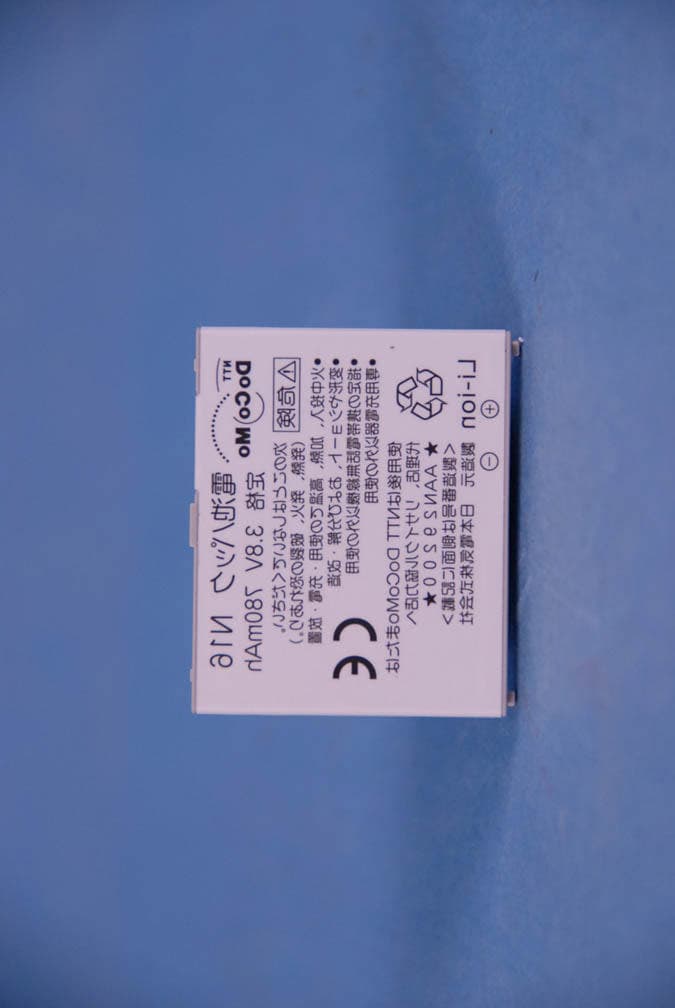
Click to zoom
Application Details
- Equipment Class
- JBP - Part 15 Class B Computing Device Peripheral
- Date of Grant
- Sep 13, 2007
- Application Purpose
- Original Equipment
- Date of Application
- Sep 13, 2007
- Equipment Note
- PCS GSM Phone with RFID
- Company
- NEC Corporation of America
- Country
- United States
Documents & Files
Document Text
Text extracted from the exhibit documents filed with the FCC. Open a document above to read the original.
Users Manual
Radio Frequency (RF) Signals THIS MODEL PHONE MEETS THE U.S. GOVERNMENT'S REQUIREMENTS FOR EXPOSURE TO RADIO WAVES. Your wireless phone contains a radio transmitter and receiver. Your phone is designed and manufactured not to exceed the emission limits for exposure to radio frequency (RF) energy set by the Federal Communications Commission of the U.S. Government. These limits are part of comprehensive guidelines and establish permitted levels of RF energy for the general population. The guidelines are based on standards that were developed by independent scientific organizations through periodic and thorough evaluation of scientific studies. The exposure standard for wireless mobile phones employs a unit of measurement known as the Specific Absorption Rate (SAR). The SAR limit set by the FCC is 1.6W/kg.* Tests for SAR are conducted using standard operating positions accepted by the FCC with the phone transmitting at its highest certified power level in all tested frequency bands. Although the SAR is determined at the highest certified power level, the actual SAR level of the phone while operating can be well below the maximum value. This is because the phone is designed to operate at multiple power levels so as to use only the power required to reach the network. In general, the closer you are to a wireless base station antenna, the lower the output. Before a phone model is available for sale to the public, it must be tested and certified to the FCC that it does not exceed the limit established by the U.S. government-adopted requirement for safe exposure. The tests are performed on position and locations (for example, at the ear and worn on the body) as required by FCC for each model. The highest SAR value for this model phone as reported to the FCC when tested for use at the ear is 0.78W/kg, and when worn on the body, is 0.288W/kg. (Body- worn measurements differ among phone models, depending upon available accessories and FCC requirements). While there may be differences between the SAR levels of various phones and at various positions, they all meet the U.S. government requirement. The FCC has granted an Equipment Authorization for this model phone with all reported SAR levels evaluated as in compliance with the FCC RF exposure guidelines. SAR information on this model phone is on file with the FCC and can be found under the Display Grant section at https:// gullfoss2.fcc.gov/oetcf/eas/reports/GenericSearch.cfm after search on FCC ID A98-FOMA- N905IMYU. For body worn operation, this phone has been tested and meets the FCC RF exposure guidelines when used with an accessory designated for this product or when used with an accessory that contains no metal and that positions the handset a minimum of 1.5 cm from the body. * In the United States, the SAR limit for wireless mobile phones used by the public is 1.6 watts/kg (W/kg) averaged over one gram of tissue. SAR values may vary depending upon national reporting requirements and the network band. FCC Regulations This mobile phone complies with part 15 of the FCC Rules. Operation is subject to the following two conditions: (1) This device may not cause harmful interference, and (2) this device must accept any interference received, including interference that may cause undesired operation. This mobile phone has been tested and found to comply with the limits for a Class B digital device, pursuant to Part 15 of the FCC Rules. These limits are designed to provide reasonable protection against harmful interference in a residential installation. This equipment generates, uses and can radiate radio frequency energy and, if not installed and used in accordance with the instructions, may cause harmful interference to radio communications. However, there is no guarantee that interference will not occur in a particular installation; if this equipment does cause harmful interference to radio or television reception, which can be determined by turning the equipment off and on, the user is encouraged to try to correct the interference by one or more of the following measures: eReorient or relocate the receiving antenna. eIncrease the separation between the equipment and receiver. eConnect the equipment into an outlet on a circuit different from that to which the receiver is connected. eConsult the dealer or an experienced radio/TV technician for help. Changes or modifications not expressly approved by the party responsible for compliance could void the user's authority to operate the equipment. 1 Making/Receiving Calls Making a Voice/Videophone Call 1 Dial the other party’s number, starting with the area code The “Phone number entry” screen appears. Always start with the area code, even for calls within the same area. A number of up to 80 digits can be entered for making a call although the numbers disappear from the display one by one from the beginning after the number exceeds 26 digits. 2 r The phone number disappears briefly and then reappears from the right as it is dialed. The “” icon flashes during dialing and remains lit during a call. The “FOMA voice in-call” screen appears. To switch to a videophone call during a voice call "Changing a call from voice to videophone"p.3 If you hear the busy tone The line is busy. Press y, and call again after a while. If you hear the message saying that the other party cannot be reached The other party's mobile phone or PHS phone is not switched on or is out of signal range. Press y , and call again after a while. If you hear the message requesting your caller ID The other party has set the Caller ID Request service to "Activate". Call again with your caller ID shown. If you set "2in1 setting" to "Dual mode" The outgoing number selection screen appears. Select a phone number. 3 To end the call, press y dMaking a videophone call 1 Phone number entry screen Xo () The "Videophone in-call" screen appears. You can talk hearing the other party's voice through the speaker. The "" icon flashes during dialing and rema…
Text truncated - open the document above for the full version.
Cover Letter(s)
Subject: RE: Questions Regarding FCC ID: A98-FOMA-N905IMYU Page 1 of 2 9/14/2007 To: Mr. Johnny Pham/ NEC Corporation of America From: Mr. Gregory Czumak/ PCTEST TCB RE: FCC ID: A98-FOMA-N905IMYU Applicant: NEC Corporation of America Correspondence Reference Number: A987736 Confirmation Number: 708170736-38 Dat of Original Email: September 12 , 2007 Subject: Request for additional information In regards to your recent TCB application referenced above, we kindly request that you provide the following additional information. 1. Please identify the precise location of the RFID transmitter schematics within the schematic diagram exhibit. ANWER: The RFID is also called FELICA in the schematic. Please see page 1 and 3 of the schematic. 2. Please describe the RFID antenna, and address Section 15.203 with respect to the antenna connector. ANSWER: The RFID antenna is built-in antenna. 3. Body SAR was tested with one transmit slot enabled. Please verify that GPRS Class 10 mode is not available to the EUT. ANSWER: When EUT is connected to the network or the communication test set Agilent8960. It reports that the supported GPRS multislot class is class 8. 4. The max SAR levels must be entered on the manual insert. Please do so, and resubmit it. ANSWER: The updated version is attached. The items indicated above must be submitted before processing can continue on the above referenced application. Sincerely, Gregory Czumak Senior Certification Engineer Quality Manager PCTEST Engineering Laboratory, Inc. 6660-B Dobbin Road Columbia, MD 21045 410-290-6652 410-290-6654 (Fax) [email protected] This communication and its attachments contain information from PCTEST En gineering Laboratory, Inc., and is intended for the exclusive use of the recipient (s) named above. It may contain information that is confidential and/or legally privileged. Any unauthorized use that may compromise that confidentiality via distribution or disclosure is prohibited. Please notify the sender immediately if you receive this communication in error, and delete it from your computer system. Usage of PCTEST email addresses for non-business related activities is strictly prohibited. No warranty is made that the e-mail or attachment(s) are free from computer virus or other defect. Thank you. Page 2 of 2 9/14/2007
External Photos
NEC FCC ID: A98-FOMA-N905IMYU EUT Photographs © 2007 PCTEST Lab. PCS GSM/GPRS Phone Model: FOMA N905iμ NEC FCC ID: A98-FOMA-N905IMYU EUT Photographs © 2007 PCTEST Lab. PCS GSM/GPRS Phone Model: FOMA N905iμ NEC FCC ID: A98-FOMA-N905IMYU EUT Photographs © 2007 PCTEST Lab. PCS GSM/GPRS Phone Model: FOMA N905iμ NEC FCC ID: A98-FOMA-N905IMYU EUT Photographs © 2007 PCTEST Lab. PCS GSM/GPRS Phone Model: FOMA N905iμ NEC FCC ID: A98-FOMA-N905IMYU EUT Photographs © 2007 PCTEST Lab. PCS GSM/GPRS Phone Model: FOMA N905iμ NEC FCC ID: A98-FOMA-N905IMYU EUT Photographs © 2007 PCTEST Lab. PCS GSM/GPRS Phone Model: FOMA N905iμ
ID Label/Location Info
FCCID Label Placement Rear View Without Battery Pack Please see a separate file for detailed drawing of a label FOMA N905iμ:IMEI Label Layout Applicant·Manufacturer: NEC Corporation Serial Number Barcode Year/month of manufacture Serial Number ID for TELEC (Japanese Accreditation) ID for JATE (Japanese Accreditation) Color of UE Product name: FOMA N905iμ NTT DoCoMo., Ltd. (Japanese accreditation mark)
Internal Photos
NEC FCC ID: A98-FOMA-N905IMYU EUT Photographs © 2007 PCTEST Lab. PCS GSM/GPRS Phone Model: FOMA N905iμ NEC FCC ID: A98-FOMA-N905IMYU EUT Photographs © 2007 PCTEST Lab. PCS GSM/GPRS Phone Model: FOMA N905iμ NEC FCC ID: A98-FOMA-N905IMYU EUT Photographs © 2007 PCTEST Lab. PCS GSM/GPRS Phone Model: FOMA N905iμ NEC FCC ID: A98-FOMA-N905IMYU EUT Photographs © 2007 PCTEST Lab. PCS GSM/GPRS Phone Model: FOMA N905iμ
Test Report
Reviewed by: FCC ID: A98-FOMA-N905IMYU FCC Pt. 15B MEASUREMENT REPORT (CERTIFICATION) Quality Manager Test Report S/N: Test Dates: EUT Type: 0708170895.A98 8/21/07 PCS GSM/GPRS Phone Page 1 of 19 © 2007 PCTEST Engineering Laboratory, Inc. REV 5.0CT 06/18/07 Applicant Name: Date of Testing: NEC Corporation of America 8/21/07 Radio Communications System Division Test Site/Location: 6535 N. State Highway 161 PCTEST Lab, Columbia, MD, USA Irving, TX 75039 Test Report Serial No.: 0708170895.A98 FCC ID: A98-FOMA-N905IMYU APPLICANT: NEC Corporation of America EUT Type: PCS GSM/GPRS Phone Model(s): FOMA N905iμ FCC Rule Part(s): FCC Part 15 Subpart B FCC Classification: FCC Class B Digital Device (JBP) Test Procedure: ANSI C63.4-2003 The device bearing the FCC Identifier specified above has been shown to comply with the applicable technical standards as indicated in the measurement report and has been tested in accordance with the measurement procedures specified in ANSI C63.4-2003 (See Test Report). These measurements were performed with no deviation from the standards. I authorize and attest to the accuracy of data. All measurements reported herein were performed by me or were made under my supervision and are correct to the best of my knowledge and belief. I assume full responsibility for the completeness of these measurements and vouch for the qualifications of all persons taking them. NVLAP accreditation does not constitute any product endorsement by NVLAP or any agency of the United States Government. PCTEST certifies that no party to this application has been denied the FCC benefits pursuant to Section 5301 of the Anti-Drug Abuse Act of 1988, 21 U.S.C. 862. PCTEST ENGINEERING LABORATORY, INC. 6660-B Dobbin Road, Columbia, MD 21045 USA Tel. 410.290.6652 / Fax 410.290.6554 http://www.pctestlab.com CERTIFICATE OF COMPLIANCE FCC Part 15B Certification Reviewed by: FCC ID: A98-FOMA-N905IMYU FCC Pt. 15B MEASUREMENT REPORT (CERTIFICATION) Quality Manager Test Report S/N: Test Dates: EUT Type: 0708170895.A98 8/21/07 PCS GSM/GPRS Phone Page 2 of 19 © 2007 PCTEST Engineering Laboratory, Inc. REV 5.0CT 06/18/07 TABLE OF CONTENTS FCC Class B MEASUREMENT REPORT.....................................................................................3 1.0 INTRODUCTION ..............................................................................................................................4 1.1 EVALUATION PROCEDURE................................................................................................................ 4 1.2 SCOPE .................................................................................................................................................. 4 1.3 PCTEST TEST LOCATION ................................................................................................................... 4 2.0 PRODUCT INFORMATION..............................................................................................................5 2.1 EQUIPMENT DESCRIPTION ................................................................................................................ 5 2.2 OPERATION MODE.............................................................................................................................. 5 2.3 EMI SUPPRESSION DEVICE(S)/MODIFICATIONS ............................................................................. 5 2.4 LABELING REQUIREMENTS ............................................................................................................... 5 3.0 DESCRIPTION OF TEST.................................................................................................................6 3.1 CONDUCTED EMISSIONS ................................................................................................................... 6 3.2 RADIATED EMISSIONS........................................................................................................................ 7 4.0 SAMPLE CALCULATIONS ..............................................................................................................8 4.1 CONDUCTED EMISSION MEASUREMENT SAMPLE CALCULATION ............................................... 8 4.2 RADIATED EMISSION MEASUREMENT SAMPLE CALCULATION.................................................... 8 5.0 TEST EQUIPMENT CALIBRATION DATA ......................................................................................9 6.0 ENVIRONMENTAL CONDITIONS .................................................................................................10 7.0 TEST DATA ....................................................................................................................................11 7.1 SUMMARY .......................................................................................................................................... 11 7.2 TEST SUPPORT EQUIPMENT ........................................................................................................... 11 7.3 RADIATED MEASUREMENT DATA ................................................................................................... 12 7.4 LINE CONDUCTED MEASUREMENT DATA ..................................................................................... 13 8.0 CONCLUSION................................................................................................................................15 9.0 TEST SETUP PHOTOGRAPHS ....................................................................................................16 10.0 EUT PHOTOGRAPHS ...................................................................................................................19 Reviewed by: FCC ID: A98-FOMA-N905IMYU FCC Pt. 15B MEASUREMENT REPORT (CERTIFICATION) Quality Manager Test Report S/N: Test Dates: EUT Type: 0708170895.A98 8/21/07 PCS GSM/GPRS Phone Page 3 of 19 © 2007 PCTEST Engineering Laboratory, Inc. REV 5.0CT 06/18/07 MEASUREMENT REPORT FCC Part 15B – Unintentional Radiators § …
Text truncated - open the document above for the full version.
Test Setup Photos
Reviewed by: FCC ID: A98-FOMA-N905IMYU FCC Pt. 15B MEASUREMENT REPORT (CERTIFICATION) Quality Manager Test Report S/N: Test Dates: EUT Type: 0708170895.A98 8/21/07 PCS GSM/GPRS Phone Page 16 of 19 © 2007 PCTEST Engineering Laboratory, Inc. REV 5.0CT 06/18/07 9.0 TEST SETUP PHOTOGRAPHS Reviewed by: FCC ID: A98-FOMA-N905IMYU FCC Pt. 15B MEASUREMENT REPORT (CERTIFICATION) Quality Manager Test Report S/N: Test Dates: EUT Type: 0708170895.A98 8/21/07 PCS GSM/GPRS Phone Page 17 of 19 © 2007 PCTEST Engineering Laboratory, Inc. REV 5.0CT 06/18/07 Reviewed by: FCC ID: A98-FOMA-N905IMYU FCC Pt. 15B MEASUREMENT REPORT (CERTIFICATION) Quality Manager Test Report S/N: Test Dates: EUT Type: 0708170895.A98 8/21/07 PCS GSM/GPRS Phone Page 18 of 19 © 2007 PCTEST Engineering Laboratory, Inc. REV 5.0CT 06/18/07
Contact Information
Applicant
Sanjay Wadhwa(Senior Manager)
Technical Contact
PCTEST Engineering Laboratory, Inc.Randy Ortanez
[email protected]410-290-6652
6660-B Dobbin Road · Columbia, Maryland · United States
Test Firm
PCTEST Engineering Laboratory, Inc.Randy Ortanez
Technical Specifications
| # | Rule Parts | Frequency Range | Power Output |
|---|---|---|---|
| 1 | 15B | - | - |
Other Applications from NEC Corporation of America

A98-MDD1075
Oct 16, 2013Cellular WCDMA and PCS GSM Phone with RFID
Equipment Class
JBP - Part 15 Class B Computing Device Peripheral
A98-MER7671
Jun 09, 2013Cellular WCDMA and PCS GSM Phone with WLAN and RFID
Equipment Class
DTS - Digital Transmission System
A98-HDN2538
Apr 24, 2013Cellular/ PCS GSM and Cellular WCDMA Phone with WLAN, Bluetooth and RFID
Equipment Class
DSS - Part 15 Spread Spectrum Transmitter
A98-FQM6833
Feb 17, 2013Digital Portable Cellular Telephone
Equipment Class
JBP - Part 15 Class B Computing Device Peripheral
A98-RSZ3446
Jan 01, 2013GSM/EGPRS/WCDMA/LTE MOBILE PHONE
Equipment Class
DSS - Part 15 Spread Spectrum Transmitter