AB6NT2100MFRM3NT2100 MFR M3 AWS radio
Avaya Canada Corporation
Click to zoom
Application Details
- Equipment Class
- TNB - Licensed Non-Broadcast Station Transmitter
- Date of Grant
- Oct 10, 2007
- Application Purpose
- Original Equipment
- Date of Application
- Oct 09, 2007
- Equipment Note
- NT2100 MFR M3 AWS radio
- Frequency Range
- 2110.00000000 - 2155.00000000
- Company
- Avaya Canada Corporation
- Country
- Canada
Documents & Files
Document Text
Text extracted from the exhibit documents filed with the FCC. Open a document above to read the original.
Cover Letter(s)
5050 40th Street NE Calgary, Alberta Canada (T3J 4P8) Request for Confidentiality September 19, 2007 American Telecommunications Certification Body, Inc. 6731 Whittier Avenue Suite C110 McLean, VA 22101 RE: Original Equipment Certification FCC Tx ID: AB6NT2100MFRM3 IC: 332D-2G1MFRM3 DearSir/Madam Please accept this request for confidentiality of sensitive information contained in this application. The request for confidentiality applies to the following sections: Exhibit 3: Technical Description Exhibit 6: Internal Photos Exhibit 8A/B: Circuit Schematics Exhibit 9A/B: Parts Lists Exhibit 11: User’s Manual Exhibit 12: Operational Description The application contains technical information that Nortel Networks deems to be trade secrets and proprietary. If made public, the information might be used to the disadvantage of the applicant in the market place. Thank you for your attention to this matter Marin Sampaleanu, P. Eng. Title: Regulatory Prime Email: [email protected] Telephone: (403) 769 4781 Fax: (403) 769 7680
Cover Letter(s)
American Telecommunications Certification Body Inc. 6731 Whittier Ave, McLean, VA 22101 September 20, 2007 RE: FCC ID: AB6NT2100MFRM3_ATCB005445 Attention: Marin Sampaleanu I have a few comments on this Application. Please note that further comments may arise in response to answers provided to the questions below. 1. Please provide the completed 731 form for this application. Please make sure to list the correct power, frequency range of operation and other pertinent data on the form. 2. Please provide the completed IC application form for this application. Please justify how this device and frequency are certifiable for Canada. 3. Please provide the appropriate Canadian test report to the appropriate RSS for this application. Please note that the 2100MHz band may not be available at this time in Canada. 4. Please note that a number of references in your reports refer to part 27 subpart H. Please note that part H of Part 27 is “Subpart H—Competitive Bidding Procedures for the 698–746 MHz Band ”. Please explain how this is pertinent to the application. Please correct the documentation and provide reference to the proper rule part for which certification is being sought. 5. Please note that table 14 of the test report (page 23) refers to RF Output Power of 1900 MHz. Please explain and please correct as necessary. 6. Please note that when measuring Occupied Bandwidth the FCC requires that the resolution bandwidth of the analyzer be set to no less that 1% of the OBW. Please note that for the listed approximate BWs of the device (3.5MHz) this would be a resolution bandwidth of no less than 35kHz. Please note that the resolution bandwidth setting used to measure OBW in the report are only 5kHz. Please note that this is not correct. Please explain, and please retest as necessary using the acceptable bandwidths allowed in the FCC rules. 7. Please note that tests on page 33-35 of the test report for antenna terminal measurements are to be taken using a resolution band width NO LESS than the 1% BW. Please note that on several you state the res BW settings were 30kHz. Please note that as the OBW of the signals are 3.5MHz and greater, the 1% allowed would be 35kHz not 30kHz. Please explain and please properly test the device using the required settings given in the rule part used. 8. Please note that IS95 is not the test standard for compliance testing of part 27 devices. Please provide data showing compliance to the rules using the FCC rule part and TIA603. 9. Please note that it is not clear from the report if the output power is composite or per channel power. Please explain. 10. Please note that based on response to the above more questions may arise. Dennis Ward mailto:[email protected] The items indicated above must be submitted before processing can continue on the above referenced application. Failure to provide the requested information may result in application termination. Correspondence should be considered part of the permanent submission and may be viewed from the Internet after a Grant of Equipment Authorization is issued. Please do not respond to this correspondence using the email reply button. In order for your response to be processed expeditiously, you must submit your documents through the AmericanTCB.com website. Also, please note that partial responses increase processing time and should not be submitted. Any questions about the content of this correspondence should be directed to the sender.
Cover Letter(s)
HI Marin If you have not done so, please upload the revised report to the application filing. Also, I notice a couple of comments in the email below that need to be addressed. The responder states that the report needs to say Part 22H . This is not true. This is a part 27 device and it needs to reflect part 27 rules. The problem with the report is that where it should reflect part 27 it gives the wrong section. For example, it references part 27 H which is not correct. The report needs to state the proper Part 27 section involved. The statement in item 6 is not correct. Please note that while 27.53(g)(1) specifically mentions the emissions just outside the signal the premise is based on the same resolution bandwidth historically allowed by the FCC for OBW measurements. It states “However, in the 1 megahertz bands immediately outside and adjacent to the licensee's frequency block, a resolution bandwidth of at least one percent of the emission bandwidth of the fundamental emission of the transmitter may be employed. The emission bandwidth is defined as the width of the signal between two points, one below the carrier center frequency and one above the carrier center frequency, outside of which all emissions are attenuated at least 26 dB below the transmitter power.” What the applicant should remember is that while the FCC can accept any test method they so choose, TCBs are restricted in operation to accept ONLY the test procedures allowed by the FCC and we must follow the FCC training guidelines. Please note that from the beginning of the TCB program the FCC has stated and maintained that Occupied bandwidth measurements, when not so specified in the rule part itself, are to be made with a resolution bandwidth no less than 1% of the occupied bandwidth. This is found in the notes on slide 19 of the 2001 FCC TCB training session and reiterated at all subsequent training sessions. It states. “When the radio service rules don’t specify a resolution bandwidth setting the guideline used is 1% of the occupied bandwidth. The video bandwidth setting should not be less than the resolution bandwidth setting.” Also, what should be remember is that while newer analyzers have digital technologies that reduce the problem of resolution bandwidth issues, they do not eliminate them. And when these newer analyzers are used to measure OBW, they automatically set the digital filter for resolution bandwidth to the proper values. Consequently the test method cannot be made analyzer specific and must be generic so as to fit all situations. What should also be remembered is that when a typical analyzer uses a resolution bandwidth significantly less than 1% of the OBW the analyzer is not be in the appropriate mode to accurately measure OBW. In order to measure OBW properly, the analyzer needs to be in spectral mode and not line mode. When an analyzers 3dB bandwidth is narrow compared to the frequency spacing of the input signal components the analyzer goes into “line” spectrum mode and is not capable of accurate signal OBW measurements. This is especially true for digital signals such as CDMA, OFDM and others. It is an incorrect assumption that because the resolution bandwidth is narrower it give a ‘better picture’ of the OBW. This is not true and what is seen is the fact that the analyzer is missing specific spectral content of the signal and thus reducing the measured bandwidth from the actual bandwidth significantly in some cases. Please remember, that these are certified under FCC rules and established test methods. Please provide data in accordance with Part 27 and the FCC required guidelines stated above (i.e. no resolution bandwidth less than 1% of the signal bandwidth.) Thanks Dennis Ward Director of Engineering American TCB Certification Resource for the Wireless Industry www.atcb.com 703-847-4700 fax 703-847-6888 direct - 703-880-4841 209-769-8316 NOTICE: This E-Mail message and any attachment may contain privileged or company proprietary information. If you received this message in error, please return to the sender.
Cover Letter(s)
5050 40th Street NE Calgary, Alberta Canada (T3J 4P8) Original Equipment Application September 19, 2007 American Telecommunications Certification Body, Inc. 6731 Whittier Avenue Suite C110 McLean, VA 22101 RE: Original Equipment Certification FCC Tx ID: AB6NT2100MFRM3 IC: 332D-2G1MFRM3 DearSir/Madam Please accept this application for the original equipment certification of the product filed under Part 2 Subpart J, for equipment operating under Part 27 of the FCC regulations . The product for which authorization is sought is Nortel CDMA 2100 MHz AWS MFRM 3. All detailed information is included in the respective exhibits as required by the Rules. Following exhibits are attached: Exhibit 1A/B: Application / Request for confidentiality Exhibit 2: Test Report Summary for AWS MFRM3 Exibit 2A: AWS MFRM3 Test reports TR1 and TR2 Exhibit 3: Technical Description Exhibit 4: Transmit Label Information Exhibit 5: External Photos Exhibit 6: Internal Photos Exhibit 7: Test Setup Photos Exhibit 8: Circuit Schematics Exhibit 9: Parts Lists Exhibit 10: RF Exposure Guidelines for PCS and Cellular Equipment Exhibit 11: User’s Manual Exhibit 12: Operational Description Please contact the undersigned for further information if necessary. Thank you for your attention to these matters. Important: Please see attached request for confidentiality Marin Sampaleanu, P. Eng. Title: Regulatory Prime Email: [email protected] Telephone: (403) 769 4781 Fax: (403) 769 7680
Cover Letter(s)
Nortel response to address the questions raised by FCC Note: Most of the required info is in the supporting documents of the application. Following is a summary of it. 1. Identify, justify and describe: a) Specific RF profiles, certification profiles, test cases, test scripts: RF Profiles Position within AWS Band Carrier Configurations Carrier Centre Channels Carrier Centre Frequencies [MHz] Bandwidth [MHz] Low 1 Carrier Ch 25 2111.25 1.25 Low 2 Carrier Ch 25, 50 2111.25, 2112.50 2.50 Low 3 Carrier Ch 25, 50, 75 2111.25, 2112.50, 2113.75 3.75 Middle 3 Carrier Ch 425, 450, 475 2131.25, 2132.50, 2133.75 3.75 High 1 Carrier Ch 875 2153.75 1.25 High 2 Carrier Ch 850, 875 2152.50, 2153.75 2.50 High 3 Carrier Ch 825, 850, 875 2151.25, 2152.50, 2153.75 3.75 Certification Profiles/Test Cases: FCC Measurement Specification FCC Limit Specification Test Description 2.1033 PA Current Specification 2.1046 RF Power Output 2.1049 Occupied Bandwidth 2.1051, 2.1057 27.53 Spurious Emissions at Antenna Terminals 2.1053, 2.1057 Field Strength Emissions 2.1055 27.54 Frequency Stability Test Scripts: All test cases were performed manually; b) Relevant subclause cross-references to RF conformance test documents and standards, also info about availability of applicable standards The test reports are submitted in accordance with the FCC Rules and Regulations, part 2, Subpart J, Sections 2.1046 through 2.1057 for equipment authorization of Nortel Networks’ CDMA 2100 MHz Radio Module. The 2100 MHz Radio Module is intended for use in the Domestic Public cellular radio telecommunications service (AWS frequency bands) and is designed according with the following standards: • CFR 47, Part 27 (Miscellaneous Wireless Communication Services), Subpart C, Technical Standards • CFR 47, part 2, Subpart J, Equipment Authorization Procedures – Equipment Authorization c) specific modulations, subchannelizations, permutations used for each test Specific Modulations used:IS-95 QPSK, IS-856 QPSK, IS-856 8PSK, IS-856 16QAM Subchannelization and Channel permutations Carrier Configurations IS-95 IS-856 IS-95 and IS-856* * Ch is configured as IS-856 Tests 1 Carrier Ch 25 Ch 25 - RF Output Power Occupied Bandwidth Spurious Conducted Emissions 1 Carrier Ch 875 Ch 875 - RF Output Power Occupied Bandwidth Spurious Conducted Emissions 2 Carrier Ch 25, 50 - - RF Output Power Occupied Bandwidth Spurious Conducted Emissions 2 Carrier Ch 850, 875 - - RF Output Power Occupied Bandwidth Spurious Conducted Emissions 3 Carrier Ch 25, 50, 75 Ch 25, 50, 75 Ch 25, 50, 75* RF Output Power Occupied Bandwidth Spurious Conducted Emissions 3 Carrier Ch 425, 450, 475 - - Frequency Stability 3 Carrier Ch 825, 850, 875 Ch 825, 850, 875 Ch 825, 850, 875* RF Output Power Occupied Bandwidth Spurious Conducted Emissions d) Specific test equipment and setup info and installed options/add-ons Spectrum Analyzer, Rhode and Schwarz, FSEM-30, SN: DE25141 Vector Signal Analyzer, Agilent, E4406A, SN: US39480709 with CDMA ONE add-on RF Power Meter, Agilent, HP438A, SN: 3318A99057 2) Description of smart-antenna and/or beamforming modes if applicable Not Applicable
Cover Letter(s)
Page 1 of 1 10/10/2007 ----- Original ----- Original Message ----- From: Generic Office of Engineering Technology To: [email protected] Sent: Friday, October 05, 2007 2:00 PM Subject: Response to Inquiry to FCC (Tracking Number 297959) Inquiry: ---Reply from Customer on 10/03/2007--- Gentlemen last week a permit but ask request was submitted for FCC ID: AB6NT2100MFRM3. ATCB is wondering what the status of this request is. Can we proceed with the grant of this application? thanks Response: AB6NT2100MFRM3 approved for e-filing upload, and approved for grant, contingent upon following: if not in exhibits already, please include info to address: Application filings should address at a minimum: 1) Please identify, justify, and describe: a) specific RF Profiles, certification profiles, test cases, test scripts that are appropriate for and were used to test this device, among those in the applicable conformance documents and standards b) relevant subclause cross-references to RF conformance test documents and standards, also info about availability of applicable standards c) specific modulations, subchannelizations, permutations used for each test d) specific test eqpt and setup info and installed options/add-ons 2) Description of smart-antenna and/or beamforming modes if applicable Do not reply to this message. Please select the Reply to an Inquiry Response link from the OET Inquiry S ystem to add any additional information pertaining to this inquiry.
External Photos
5050 40th Street NE Calgary, Alberta Canada (T3J 4P8) EXHIBIT 5 EXTERNAL PHOTOS Applicant: Nortel Networks For original Equipment Application on: FCC: AB6NT2100MFRM3 IC: 332D-2G1MFRM3 This document contains Proprietary information of Nortel Networks. This information is considered to be confidential and should be treated appropriately. Nortel Networks MFRM3 Assembly Front View Fan Assembly Mounted This document contains Proprietary information of Nortel Networks. This information is considered to be confidential and should be treated appropriately. Nortel Networks MFRM3 Assembly Front View Fan Assembly Removed
ID Label/Location Info
5050 40th Street NE Calgary, Alberta Canada (T3J 4P8) EXHIBIT 4 TRANSMIT LABEL INFORMATION Applicant: Nortel Networks For Original Equipment Application on: FCC: AB6NT2100MFRM3 IC: 332D-2G1MFRM3 DESIGN AUTHORITYINITIAL APPLICATIONTITLEDRAWING NUMBER SCALE SIZE SHEET B 1 OF NORTEL PROPRIETARY INFORMATION: THE INFORMATION CONTAINED IN THIS DOCUMENT IS THE PROPERTY OF NORTEL, EXCEPT AS SPECIFICALLY AUTHORIZED IN WRITING BY NORTEL. THE HOLDER OF THIS DOCUMENT SHALL (1) KEEP ALL INFORMATION HEREINCONFIDENTIAL AND SHALL PROTECT SAME IN WHOLE OR IN PART FROM DISCLOSURE AND DISSEMINATION TO ALL THIRD PARTIES AND(2) USE SAME FOR OPERATING AND MAINTENANCE PURPOSES ONLY. (CorelDRAW 9 JAN 25, 2005) PRINTED IN CANADA DATE REVISION FULL 11 SEPT 07 A N0136261 2 NTGZ70CAE5 REGULATORY LABEL, MFRM-3 1.7/2.1GHz 2.25" BACKGROUND COLOUR BTS LIGHT GRAY PER S-33470 (PANTONE NO. COOL GRAY 5C) NORTEL LOGO & GLOBE MARK WHITE PER S-33294 BACKGROUND COLOUROXFORD GRAY PER S-33477(PANTONE NO. COOL GRAY 11C) 3.00" LR101956 CUS NOTES:1. UNLESS OTHERWISE SPECIFIED, ALL DIMENSIONS ARE EXPRESSED IN INCHES. TOLERANCES SHALL BE;TWO DECIMAL PLACES = +/- .01THREE DECIMAL PLACES = +/- .005 ALL LABEL CORNERS SHALL HAVE A .03 RADIUS. 2. THIS DESIGN FILE WAS CREATED IN ACCORDANCE WITH STD. 1517.20. THE LABELS /ARTWORK SHALL MEET ALL THE REQUIREMENTS OF NPS-90942. 3. THE ARTWORK (SEE SHEET 2) SHALL BE PLOTTED AT A MINIMUM OF 1200 DPI. THE FONT(S) SHALL BE: CB UNIVERS 67 CONDENSED BOLD 4. MATERIAL: OPTION #1:.010 POLYCARBONATE PER R0115902FINISH: VELVET/MATTE ADHESIVE: .002 PRESS SENSITIVE WITH PEEL-OFF LINER PER R0117260 OPTION #2: 5. NORTEL NETWORKS OBSERVATIONAL STANDARDS FOR COLORING (CORP. STD. 2701.01); BACKGROUND: SEE VIEW, SHEET 1NORTEL LOGO AND GLOBE MARK: SEE VIEW, SHEET 1 TEXT & GRAPHICS: SEE VIEW, SHEET 1 OPTION #2:OPTION #1: TEXT, GRAPHICS, NORTEL LOGO & GLOBE MARK MUST BE BLACK PER STANDARD S-33154 6. ALL MATERIALS AND FINISHES SHALL BE COMPLIANT TO NORTEL SPEC NPS00200. 7. LABEL TO BE REVERSE SCREEN PRINTED PER NPS90942-2. THE LABEL MATERIAL AND PRINTER MUST CONFORM TO: (A) THE LABEL MATERIAL SHALL BE A 3M-7872 THERMAL TRANSFER POLYESTER LABEL MATERIAL. (B) THE LABEL SHALL BE PRINTED ON A ZEBRA 105SL THERMAL TRANSFER PRINTER. (C) THE LABEL SHALL BE IMPRINTED WITH A THERMAL TRANSFER PRINTING RIBBON RICOH B110C. BACKGROUND CAN BE THE STOCK LABEL COLOR. CDMA MFRM-3 1.7/2.1GHz Radio ModuleModel No. NTGZ70CAE5FCC ID: AB6NT2100MFRM3IC: 332D-2G1MFRM3 0.75" TEXT & GRAPHICSWITHIN BTS LIGHTGRAY AREABLACK PER S-33154 N0136261-M1 REVISION A SCALE= 1/1 SHEET 2 OF 2 LR101956 CUS CDMA MFRM-3 1.7/2.1GHz Radio ModuleModel No. NTGZ70CAE5FCC ID: AB6NT2100MFRM3IC: 332D-2G1MFRM3
RF Exposure Info
5050 40th Street NE Calgary, Alberta Canada (T3J 4P8) EXHIBIT 10 RF EXPOSURE GUIDELINES Applicant: Nortel Networks For Original Equipment Application on: FCC: AB6NT2100MFRM3 IC: 332D-2G1MFRM3 RF Exposure Guidelines for Cellular, PCS and LMDS Antenna Sites Document no: SI-EMR-R01.5 Authors: Product Integrity BWA – RF Engineering Microwave Radio Design Proprietary Northern Telecom Antenna Siting Guideline 3 The information disclosed herein is proprietary to Nortel Networks or others and is not to be used by or disclosed to unauthorized persons without the written consent of Nortel. The recipient of this document shall respect the security status of the information. 1.0 Executive Summary This document serves as a guideline for the deployment and installation of Nortel Networks’ wireless base station equipment with respect to the control of electromagnetic radiation (EMR) exposure. The objective is to provide guidance on where antennas can be deployed, how to calculate power densities and safe distances and how to protect users from excessive exposure to electromagnetic radiation. This guideline is in response to recent regulatory requirements originating in the US aimed at controlling human exposure to EMR. Safe distance formulae for base stations: Limits Application Uncontrolled r [ meters ] Controlled r [ meters ] Cellular r0. 300 ER P= r0. 135 ER P= PCS r0. 228 ER P= r= 0.102 ERP DCS r0. 228 ER P= r=0.102ERP LMDS r = 1 r = 0.4 P-to-P Microwave Radio r = 1 r = 0.4 Uncontrolled refers to situations where individuals are either unaware or not in control of their exposure to the electromagnetic fields in question. This typically pertains to the general public. Controlled refers to situations where individuals are both aware of and in control of their exposure to the electromagnetic fields in question. This typically pertains to trained staff that is in contact with these fields as a result of their employment and have authority to limit their exposure. Note: This document includes DCS in its examples. If the EU adopts ENV50166, or any other EMR standard, then that document will replace this as the guideline for DCS products. Until that happens, these limits can be used to ensure due diligence on Nortel Networks’ behalf. Northern Telecom Antenna Siting Guideline iv Table of Contents 1.0 Executive Summary ................................................................................. ii 2.0 Introduction ............................................................................................. 1 3.0 Guideline ............................................................................................. 2 3.1 MPE Limits ............................................................................................. 3 3.2 Safe Distance and Power Density Calculations ................................. 5 3.2.1 Minimum Safe Distance ............................................................ 6 3.2.2 Power Density Calculation ........................................................ 8 3.3 Site Planning ............................................................................................ 9 4.0 Other Components ................................................................................. 10 5.0 Assumptions ........................................................................................... 11 6.0 References .............................................................................................. 12 7.0 Acronyms ............................................................................................... 12 Northern Telecom Antenna Siting Guideline 1 2.0 Introduction Regulatory bodies in the US, Federal Communications Commission (FCC), and Canada, Health Canada, are imposing Maximum Permissible Exposure (MPE) limits. FCC’s OET Bulletin #65 (versions in progress) addresses calculation and measurement procedures to determine compliance with the FCC limits which includes the 800 MHz cellular and 1.9 GHz PCS bands. The equipment and its associated deployment must comply with FCC Guidelines, ET Docket No. 93-62, Released August 1, 1996, (FCC 96-326). This standard is largely based on the limits and test methods outlined in IEEE C95.1-1982, NCRP Report No. 86 and C95.3-1982 respectively. The applicable portions of both are summarized in this document to assist in the antenna site planning to ensure compliance. The exposure limits are currently in effect. The requirement for installers to evaluate the exposure at an installation takes effect on Sept. 1/97. The exposure limits should apply now to all known sites since existing facilities are not exempt or grand fathered from the new rules. The FCC has determined that certain sites will require “Environmental Evaluations” in order to show compliance to the standards. Adhering to these guidelines can ensure compliance to the standard, and therefore can be the basis for the Environmental Evaluation. Please note that some installations do not require such routine evaluation: exceptions are noted further in this document. Adherence to these guidelines is recommended to promote safety. An installation of equipment that is identified as exempt may require an Environmental Evaluation if the combined energy of other Radio Systems at the site and the new installation could reasonably exceed the safety limits. Environmental Evaluations are kept on hand, as opposed to file with the FCC, unless requested by the FCC for substantiation. Where Nortel Networks is responsible for installing or engineering base stations, the person in charge should be aware of and have access to documentation for making an Environmental Evaluation. Also, Nortel Networks will need to maintain documentation for assurances to the FCC that Environmental Evaluations have been conducted for each radio station that uses our Experimental Radio License, or STA, where the station transmits at 100 Watt ERP or more. Northern Telecom Antenna Siting Guideline 2 3.0 Guideline The object…
Text truncated - open the document above for the full version.
Test Report
5050 40th Street NE Calgary, Alberta Canada (T3J 4P8) EXHIBIT 2 TEST REPORT SUMMARY Applicant: Nortel Networks For Original Equipment Application on: FCC: AB6NT2100MFRM3 IC: 332D-2G1MFRM3 NORTEL CDMA BTS Development MFRM-3 AWS FCC Part 27 Test Summary ecurity status: Proprietary rized persons. While copies may be printed, it is not recommended. Viewing of the aster electronically ensures access to the current issue. Any hardcopies must be regarded as ncontrolled copies. ortel Networks Proprietary: he information herein is not to be disclosed without permission of its author. opyright © 2005 Nortel Networks All rights reserved Issue: 00.01 Issue date: September 16, 2007 S Document Prime: Yan Papernov, Igor Acimovic DISCLAIMER: The master of this document is stored on an electronic database and is "write protected"; it may be altered only by autho m u N T C MFRM-3 AWS FCC Part 27 Test Summary Page 2 of 10 Document Control All other soft and hard copies are to be considered uncontrolled. It is the responsibility of the reader to ensure that the latest approved release of this document is being used. Issue: 00.01 Author: Yan Papernov Nortel Proprietary September 16, 2007 MFRM-3 AWS FCC Part 27 Test Summary Page 3 of 10 Table of Contents 1 INTRODUCTION...............................................................................................................................................5 2 SUMMARY..........................................................................................................................................................6 2.1 RADIATED EMISSIONS....................................................................................................................................6 2.2 CONDUCTED EMISSIONS.................................................................................................................................6 Issue: 00.01 Author: Yan Papernov Nortel Proprietary September 16, 2007 MFRM-3 AWS FCC Part 27 Test Summary Page 4 of 10 List of Tables Table 1. MFRM-3 AWS FCC Part 27 Test Summary................................................................................... 6 Table 2. Spurious Emissions at the AWS MFRM3 Ant. Port one Carrier IS95............................................ 6 Table 3. Spurious Emissions at the AWS MFRM3 Ant. Port two Carrier IS95........................................... 6 Table 4. Spurious Emissions at the AWS MFRM3 Ant. Port Three Carrier IS-95........................................ 7 Table 5. Spurious Emissions at the AWS MFRM3 Ant. Port One Carrier Band IS856 (QPSK).................. 7 Issue: 00.01 Author: Yan Papernov Nortel Proprietary September 16, 2007 MFRM-3 AWS FCC Part 27 Test Summary Page 5 of 10 1 Introduction The purpose of this document is to present the summary of the tests that have been performed on the MFRM-3 AWS product to comply it to the FCC Part 27 requirements. Issue: 00.01 Author: Yan Papernov Nortel Proprietary September 16, 2007 MFRM-3 AWS FCC Part 27 Test Summary Page 6 of 10 2 Summary 2.1 Radiated Emissions Table 1. MFRM-3 AWS FCC Part 27 Test Summary Test N. Description Test Specification Test Result Note 1 Radiated Spurious Emissions E-Field FCC Part 27 (g) FCC Part 2.1053 FCC Part 21057 PASS Worst case margin 14.8 dB Indoor Radio Rack 4x MFRM-3 AWS radios +24VDC and -48VDC 2.2 Conducted Emissions Table 2. Spurious Emissions at the AWS MFRM3 Ant. Port one Carrier IS95 Frequency Spurious Emissions Level (dBm) Margin to FCC Limit of -13 dBm (dB) 2109 to 2110 MHz (lower adjacent 1 MHz); Channel 25 -25.82 12.82 2155 to 2156 MHz (upper adjacent 1 MHz); Channel 875 -24.51 11.51 9 kHz to lower adjacent 1MHz (RBW=1MHz) -20.03 7.03 upper adjacent 1MHz to 5 GHz (RBW=1MHz) -20.21 7.21 5 GHz to 22 GHz (RBW=1MHz) -37.58 24.58 Table 3. Spurious Emissions at the AWS MFRM3 Ant. Port two Carrier IS95 Frequency (Band) Spurious Emissions Level (dBm) Margin to FCC Limit of -13 dBm (dB) Issue: 00.01 Author: Yan Papernov Nortel Proprietary September 16, 2007 MFRM-3 AWS FCC Part 27 Test Summary Page 7 of 10 2109 to 2110 MHz (lower adjacent 1 MHz); Channel 25, 50 -24.24 11.24 2155 to 2156 MHz (upper adjacent 1 MHz); Channel 850, 875 -22.89 9.89 9 kHz to lower adjacent 1MHz (RBW=1MHz) -16.49 3.49 upper adjacent 1MHz to 5 GHz (RBW=1MHz) -16.06 3.06 5 GHz to 22 GHz (RBW=1MHz) -36.50 23.50 Table 4. Spurious Emissions at the AWS MFRM3 Ant. Port Three Carrier IS-95 Frequency (MHz) Spurious Emission s Level (dBm) Margin to FCC Limit of -13 dBm (dB) 2109 to 2110 MHz (lower adjacent 1 MHz); Channel 25, 50, 75 -24.19 11.19 2155 to 2156 MHz (upper adjacent 1 MHz); Channel 825, 850, 875 -24.67 11.67 9 kHz to lower adjacent 1MHz (RBW=1MHz) -16.35 3.35 upper adjacent 1MHz to 5 GHz (RBW=1MHz) -16.71 3.71 5 GHz to 22 GHz (RBW=1MHz) -44.33 31.33 Table 5. Spurious Emissions at the AWS MFRM3 Ant. Port One Carrier Band IS856 (QPSK) Frequency (MHz) Spurious Emissions Level (dBm) Margin to FCC Limit of -13 dBm (dB) Issue: 00.01 Author: Yan Papernov Nortel Proprietary September 16, 2007 MFRM-3 AWS FCC Part 27 Test Summary Page 8 of 10 2109 to 2110 MHz (lower adjacent 1 MHz); Channel 25 -27.84 14.84 2155 to 2156 MHz (upper adjacent 1 MHz); Channel 875 -25.82 12.82 9 kHz to lower adjacent 1MHz (RBW=1MHz) -18.55 5.55 upper adjacent 1MHz to 5 GHz (RBW=1MHz) -20.54 7.54 5 GHz to 22 GHz (RBW=1MHz) -37.44 24.44 Issue: 00.01 Author: Yan Papernov Nortel Proprietary September 16, 2007 MFRM-3 AWS FCC Part 27 Test Summary Page 9 of 10 Spurious Emissions at the AWS MFRM3 Ant. Port Three Carrier IS856 (8PSK) Spurious Emissions Level (dBm) Margin to FCC Limit of -13 dBm (dB) Frequency (MHz) 3Carrier 8PSK 3Carrier 2109 to 2110 MHz (lower adjacent 1 MHz); Channel 25, 50, 75 -23.22 10.22 2155 to 2156 MHz (upper adjacent 1 MHz); Channel 825, 850, 875 -21.75 8.75 9 kHz to lower adjacent 1MHz (RBW=1MHz) -15.16 2.16 upper adjacent 1MHz to 5 GHz (RBW=1MHz) -16.20 3.20 5 GHz to 22 GHz (RBW=1MHz) -38.19 25.18 Spurious Emissions at the AWS MFRM3 Ant. Port…
Text truncated - open the document above for the full version.
Test Report
5050 40th Street NE Calgary, Alberta Canada (T3J 4P8) EXHIBI…
Text truncated - open the document above for the full version.
Contact Information
Applicant
Gwendolyn Faino(Legal Director)
Technical Specifications
| # | Rule Parts | Frequency Range | Power Output | Emission | Tolerance |
|---|---|---|---|---|---|
| 2 | 27 | 2.11 GHz - 2.15 GHz | 76 W | 1M25D9W | 0.003 ppm |
Other Applications from Avaya Canada Corporation

AB6NT2100V3231
Mar 30, 2008AWS Radio
Equipment Class
TNB - Licensed Non-Broadcast Station Transmitter
AB6BTS9000
Dec 19, 2007Base Transceiver Station
Equipment Class
PCB - PCS Licensed Transmitter
AB6NTQ220AB
Jun 12, 2007NTQ220ABE5 Radio Module
Equipment Class
TNB - Licensed Non-Broadcast Station Transmitter
AB6BTS6000D
Jun 07, 2007GSM 6000 Base Transceiver Station
Equipment Class
PCB - PCS Licensed Transmitter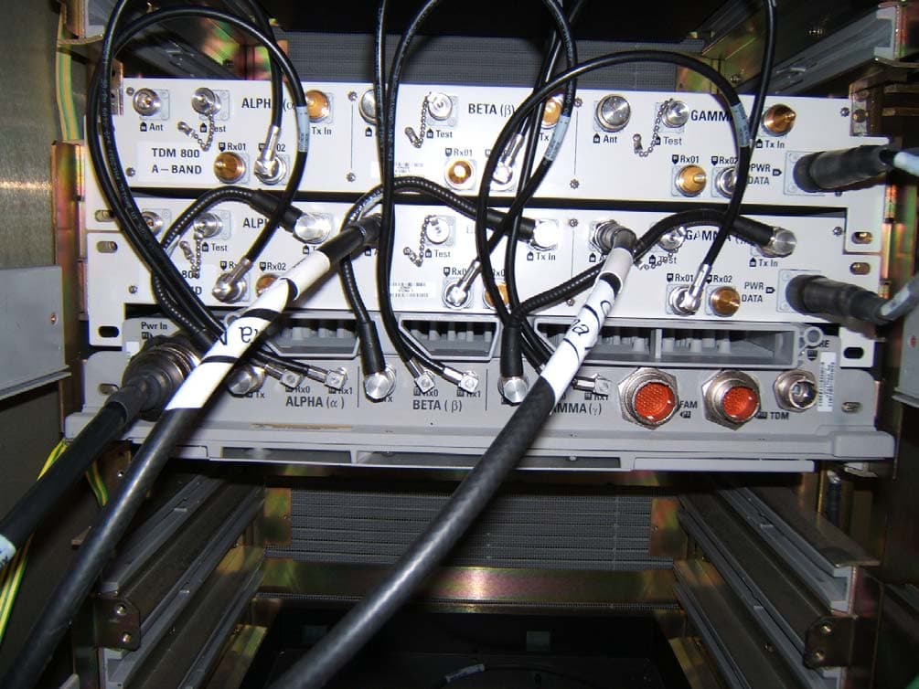
AB6NT1900MFRM3
Jun 05, 2007CDMA Cellular Base Station
Equipment Class
PCB - PCS Licensed Transmitter