ABZ99FT3095BNon Broadcast Transmitter
Motorola Solutions, Inc.
Click to zoom
Application Details
- Equipment Class
- TNB - Licensed Non-Broadcast Station Transmitter
- Date of Grant
- Mar 26, 2023
- Application Purpose
- Original Equipment
- Date of Application
- Mar 26, 2023
- Equipment Note
- Non Broadcast Transmitter
- Frequency Range
- 136.00000000 - 174.00000000
- Company
- Motorola Solutions, Inc.
- Country
- United States
Documents & Files
Document Text
Text extracted from the exhibit documents filed with the FCC. Open a document above to read the original.
Users Manual
APPLICANT: MOTOROLA SOLUTIONS EQUIPMENT TYPE: ABZ99FT3095B 109AB-99FT3095B EXH IBIT D User Information Us er Information Tune-up and user / operational manual information are provided in the following exhibits. EXHIBIT DESCRIPTION D1 Tune-Up Procedure D2 User / Operational Manual APPLICANT: MOTOROLA SOLUTIONS EQUIPMENT TYPE: ABZ99FT3095B 109AB-99FT3095B EXH IBIT D1 Tune-Up Procedure Tune-Up Procedure A procedure to ensure that the device is tuned to the correct frequency / frequency range and that it is operating at the proper level. This exhibit is only required for licensed transmitters. Content from Chapter 10 of the document “MOTOTRBO™ SLR 8000 Repeater Bas ic Service and Installation Manual” (part number MN002253A01-AH, November 2022) is included in the following pages. Chapter 10 SLR 8000 Programming and Tuning 10.1 Programming and Tuning Introduction This section provides an overview of the MOTOTRBO Customer Programming Software (CPS) and the MOTOTRBO Tuner application for use on Windows 7, Windows 8, or Windows 8.1. These two MOTOTRBO applications are used for the configuration and alignment of the SLR 8000 Base Station/ Repeater. 10.2 Customer Programming Software Setup The Customer Programming Software setup, shown in Figure 50: Customer Programming Software Setup on page 97 is used to program the base station/repeater. See Figure 51: Front view of SLR 8000 Base Station/Repeater on page 98 and Figure 52: Rear view of SLR 8000 Base Station/ Repeater on page 98 for the actual connectors on the front and rear panels of the base station/ repeater. NOTE: See appropriate program on-line help files for the programming procedures. CAUTION: Computer USB ports can be sensitive to Electronic Discharge. Employ proper ESD practices (wrist strap, grounding, etc.) and do not touch exposed contacts on cables when connected to a computer. Figure 50: Customer Programming Software Setup Front Panel USB AC USB 120 / 240 VAC * OPTIONAL Station Tx Port (N-type Female) Rx Port (BNC Female) AUX WL1* DC 13.6 VDC ( typical ) or 27.2 VDC ( typical ) Either One or Both Standard Type “A” to Type “B” USB cable Rear Panel MN002253A01-AH SLR 8000 Programming and Tuning 97 Applicant: Motorola SolutionsEquipment Type: ABZ99FT3095B / 109AB-99FT3095B Tune-Up ProcedureExhibit D1 1 of 19 Figure 51: Front view of SLR 8000 Base Station/Repeater 21 Table 49: Callout Legend LabelDescription 1Microphone Connector 2USB Connector Figure 52: Rear view of SLR 8000 Base Station/Repeater 4 5 321 TxRx Rx 21 REF ANT AUX Table 50: Callout Legend LabelDescription 1AC Inlet Connector 2DC Inlet Connector 3Rx RF Connector 4Aux Connector 5Tx RF Connector MN002253A01-AH Chapter 10 : SLR 8000 Programming and Tuning 98 Applicant: Motorola SolutionsEquipment Type: ABZ99FT3095B / 109AB-99FT3095B Tune-Up ProcedureExhibit D1 2 of 19 10.3 Tuning the Reference Oscillator Alignment This feature is used to adjust the reference oscillator of the SLR 8000 Base Station/Repeater. This alignment process should be done as maintenance schedules and regulations require or if the Modem FRU has been replaced in the base station/repeater. Procedure: 1Connect the base station/repeater's transmitter antenna port to the Communication Analyzer. 2Power the base station/repeater from either an AC or DC source. 3Launch the Tuner application. 4To begin reading the base station/repeater's tuning softpot values, click Read 5Under the TX menu in the tree view, select Ref Oscillator Figure 53: Tx Menu Tree (Ref. Oscillator) 6Configure the current operating frequency into the Communications Analyzer. 7To key up the base station/repeater, click PTT Toggle 8Adjust the working softpot value until the frequency is within the performance specifications (+/-40 Hz for UHF and VHF) from the frequency point. 9To de-key the base station/repeater, click PTT Toggle 10To save the tuned softpot value into the base station/repeater codeplug. click Write 10.4 Base Station/Repeater Tuning Setup A personal computer (PC), Windows ™ operating system, and the MOTOTRBO Tuner application are required to align the base station/repeater. To perform the tuning procedures, the base station/repeater must be connected to the PC and test equipment setup as shown in the following figure. Figure 54: SLR 8000 Base Station/Repeater Tuning Equipment Setup Transmit Service Monitor or Counter 20 dB Pad Front Panel AC USB 120 / 240 VAC Station Tx Port (BNC Female) AUX DC 13.6 VDC * OPTIONAL Either One or Both Rear Panel Standard Type “A” to Type “B” USB cable WL2* USB Wattmeter MN002253A01-AH Chapter 10 : SLR 8000 Programming and Tuning 99 Applicant: Motorola SolutionsEquipment Type: ABZ99FT3095B / 109AB-99FT3095B Tune-Up ProcedureExhibit D1 3 of 19 10.5 Tuning the Rx Audio Level Set The procedure outlined in this section is used to set the receive output audio level from the SLR 8000 Base Station/Repeater for a given RF deviation of the received RF signal. Perform this procedure any time the Rx audio level needs adjustment. NOTE: The sequence of steps in this procedure is crucial in order to observe the effect of softpot setting on the Rx output at pin #7 during the adjustments. Procedure: 1Connect the base station/repeater's receiver antenna port to the Communication Analyzer. 2Power the base station/repeater from either an AC or DC source. 3Set the Communication Analyzer to output a -47 dBm RF signal modulated with a 1 kHz tone at 60% of full deviation on the tuning frequency. The tuning frequency is the value displayed on the Tuner GUI under the heading of "Frequency Points". NOTE: The Tuner aligns this parameter in a 12.5 kHz channel spacing, so 60% is 1.5 kHz of deviation. If the CPS is set for 25 kHz operation, the base station/repeater automatically scales the deviation by a factor of two when it is outside the Tuner application. Programmed TPL and DPL squelch requirements are automatically disabled for the tuning frequency while in the Tuner application. 4Launch the Tuner application. 5To read th…
Text truncated - open the document above for the full version.
Attestation Statements
TO: Federal Communication Commission Equipment Authorization Division Application Processing Branch 7435 Oakland Mills Rd Columbia, MD 21046 February 17, 2023 Pursuant to FCC 22-84 Report and Order and KDB 986446 D01 Covered Equipment v01, the Commission adopted new FCC requirements to protect the nation’s networks and supply chains from equipment that poses an unacceptable risk to national security or the safety of U.S. persons. Specifically, the Commission adopted rules that prohibit equipment authorization for “covered” telecommunications equipment and video surveillance equipment produced by entities identified on the Commission’s Covered List. Certification designating a U.S. agent for service of process. As required by section 2.911(d)(7), the applicant must designate a contact located in the United States for purposes of acting as the applicant’s agent for service of process, regardless of whether the applicant is a domestic or foreign entity. Robert Sarocka (“the applicant”) concent to accept the service of process. Robert Sarocka Motorola Solutions 2000 Progress Parkway, Schaumburg, IL 60196 847-344-6075 [email protected] FCC ID: ABZ99FT3095B FRN: 0025009739 Thank you. Regards, 2/17/23 Robert Sarocka Engineering Manager
Attestation Statements
TO: Federal Communication Commission Equipment Authorization Division Application Processing Branch 7435 Oakland Mills Rd Columbia, MD 21046 February 17, 2023 Pursuant to FCC 22-84 Report and Order and KDB 986446 D01 Covered Equipment v01, the Commission adopted new FCC requirements to protect the nation’s networks and supply chains from equipment that poses an unacceptable risk to national security or the safety of U.S. persons. Specifically, the Commission adopted rules that prohibit equipment authorization for “covered” telecommunications equipment and video surveillance equipment produced by entities identified on the Commission’s Covered List. Certifications FCC ID: ABZ99FT3095B concerning “covered” equipment. Section 2.911(d)(5)(i)-(ii). Robert Sarocka (“the applicant”) certifies that as of the date of the filing of the application, the applicant is not identified on the covered list as an entity producing covered equipment. Thank you. Regards, 2/17/23 Robert Sarocka Engineering Manager Motorola Solutions 2000 Progress Parkway, Schaumburg, IL 60196 847-344-6075 [email protected]
Cover Letter(s)
TO: Federal Communication Commission Equipment Authorization Division Application Processing Branch 7435 Oakland Mills Rd Columbia, MD 21046 ATTENTION: Federal Communication Commission Equipment Authorization To whom it may concern, We would like to submit for Certification to FCC: ABZ99FT3095B. Please find in the following application all related documentation to support this New Single Certification. We would appreciate your prompt attention to the submittal. Applicant Company name: Motorola Solutions, Inc. Contact Name: Bob Sarocka Address: 2000 Progress Parkway, Schaumburg, IL 60196 Telephone No: 847-344-6075 Email: [email protected] FCC ID Number: ABZ99FT3095B 2/17/23 Robert Sarocka Engineering Manager Motorola Solutions
Cover Letter(s)
FCC ID: ABZ99FT3095B ___________________________________________________________________________________________________________ Motorola Solutions Malaysia Sdn Bhd, Plot2A, Medan Bayan Lepas, 11900 Penang, Malaysia EXHIBIT 13C Date: March 21, 2023 Rick King Certification Department 1516 Centre Circle Downers Grove, Illinois 60515 Telephone: 630 495-9770 Email: [email protected] ELITE ELECTRONIC ENGINEERING Subject: Extended Frequencies Justification for Certification of Transmitter with FCC ID: ABZ99FT3095B Dear Sir, In accordance with updated requirements pertaining to Publication KDB 634817, Frequency Range Listings for Certification Grants, Motorola Solutions hereby submits attestation that the transmitter described in this submission includes continuous frequencies that are not listed in rule part 90. For the FCC’s Rule Parts 22, 74, 80 and 90 applications, this radio is used in systems by Federal and Public Safety agencies including Police, Fire, and Emergency Medical Services, etc. Please note that Licensed End Users do not have access to any external controls that will allow them to program the equipment. Equipment programming is the responsibility of Authorized Service Personnel. Also, the radio complies with 47 CFR Part 90.203(e) and 80.203(b), in that the operator cannot directly program the transmit frequencies using the normally accessible external controls. It is understood that a grant note code may be added to the grant which indicates this required operation. Sincerely, Bob Sarocka Engineering Manager E-mail: [email protected]
Cover Letter(s)
FCC ID: ABZ99FT3095B ___________________________________________________________________________________________________________ Motorola Solutions Malaysia Sdn Bhd, Plot2A, Medan Bayan Lepas, 11900 Penang, Malaysia EXHIBIT 13C Date: March 21, 2023 Rick King Certification Department 1516 Centre Circle Downers Grove, Illinois 60515 Telephone: 630 495-9770 Email: [email protected] ELITE ELECTRONIC ENGINEERING Subject: Part 90.203 (j) (5) Certification Statement FCC ID: ABZ99FT3095B Dear Sir, Motorola Solutions, Inc certifies that it’s digital base station transmitter FCC ID: ABZ99FT3095B, meets a spectrum efficiency standard of one voice channel per 6.25kHz of channel bandwidth. Additionally, Motorola Solutions, Inc certifies the equipment is capable of supporting a minimum data rate of 4800 bits per second per 6.25 kHz of channel bandwidth. . Sincerely, Bob Sarocka Engineering Manager E-mail: [email protected]
External Photos
APPLICANT: MOTOROLA SOLUTIONS EQUIPMENT TYPE: ABZ99FT3095B 109AB-99FT3095B EXHIB IT C Photographs of the Device Photographs – Index EXHIBIT DESCRIPTION C1-1 C1-2 C1-3 C1-4 External Front View of Base Radio External Front View of Base Radio, Top Cover and Front Panel Removed External Back View of Base Radio FCC / IC Identification Label APPLICANT: MOTOROLA SOLUTIONS EQUIPMENT TYPE: ABZ99FT3095B 109AB-99FT3095B EXHI BIT C1-1 Photographs of the Device Ex ternal Front View of Base Radio APPLICANT: MOTOROLA SOLUTIONS EQUIPMENT TYPE: ABZ99FT3095B 109AB-99FT3095B EXH IBIT C1-2 Photographs of the Device E xternal Front View of Base Radio, Top Cover and Front Panel Removed APPLICANT: MOTOROLA SOLUTIONS EQUIPMENT TYPE: ABZ99FT3095B 109AB-99FT3095B EXH IBIT C1-3 Photographs of the Device Ex ternal Back View of Base Radio APPLICANT: MOTOROLA SOLUTIONS EQUIPMENT TYPE: ABZ99FT3095B 109AB-99FT3095B EXHI BIT C1-4 Photographs of the Device FCC / IC Identification Label
ID Label/Location Info
APPLICANT: MOTOROLA SOLUTIONS EQUIPMENT TYPE: ABZ99FT3095B 109AB-99FT3095B EXHIBIT A P hotographs of the Device Phot ographs – Index EXHIBIT DESCRIPTION A1 A2 ID Label Location FCC / IC Identification Label APPLICANT: MOTOROLA SOLUTIONS EQUIPMENT TYPE: ABZ99FT3095B 109AB-99FT3095B EXHIBIT A1 P hotographs of the Device ID Label Location APPLICANT: MOTOROLA SOLUTIONS EQUIPMENT TYPE: ABZ99FT3095B 109AB-99FT3095B EXHIBIT A2 P hotographs of the Device FCC / IC Identification Label
RF Exposure Info
Motorola Solutions Canada, Inc. UPN Number: 3790B Company Number: 109AB HVIN: SLR 5700-VHFB Page 1 RF Exposure Technical Brief This Technical Brief calculates the minimum separation distance from an antenna, connected to the subject base station, such that the power density value listed in RSS-102, Radio Frequency (RF) Exposure Compliance of Radiocommunications Apparatus (All Frequency Bands) Issue 5 Table 6 is not exceeded. The analysis is for a typical installation using a structure mounted antenna. Within the frequency range that the subject equipment operates, 138 MHz – 174 MHz the permitted exposure limit is frequency dependent per the equation 0.6455*sqrt(f). Table 1 lists the maximum permitted exposure limits for the lowest and highest operating frequencies. The smaller maximum permissible exposure limit will be used for the computation because it requires a larger separation distance from the antenna to the exposed person. Table 1 - Maximum Permissible Exposure Limits Controlled Environment Frequency 138 MHz 174 MHz Limit 7.6 W/m 2 8.5 W/m 2 Example Calculations for GTR8000, UHF Transmitter: The example configuration is a single frequency site, with minimal RF network losses, set to zero for this example, between the transmitter output connector and the antenna input connector. The antenna has an omni directional pattern in the horizontal plane. Table 2 lists the key RF system and antenna parameters. Table 2 - Transmitter Configuration Frequency 138-174 MHz Base Station Output Power 110 W RF Network Loss 0 dB Antenna Type DS1F00F36U-D 0 dBd / 2.1 dBi (Omni) Antenna length 2.5 m Controlled Environment: Cylindrical Method 1 Using Equation 1 the spatially averaged plane-wave equivalent power density parallel to the antenna in the vertical plane is estimated by dividing the net input power to the antenna by the surface area of an imaginary cylinder at a distance R from the antenna, with the height of the cylinder equal to the length of the antenna 2 . Rh Pnet S 2 (1) 1 Federal Communications Commission Office of Engineering & Technology, OET Bulletin 65, “Evaluating Compliance with FCC Guidelines for Human Exposure to Radiofrequency Electromagnetic Fields”, Edition 97-01, page 32, Tell’s cylindrical model. 2 Federal Communications Commission Office of Engineering & Technology, OET Bulletin 65, “Evaluating Compliance with FCC Guidelines for Human Exposure to Radiofrequency Electromagnetic Fields”, Edition 97-01, page 32, Tell’s cylindrical model. Motorola Solutions Canada, Inc. UPN Number: 3790B Company Number: 109AB HVIN: SLR 5700-VHFB Page 2 Where: S = power density, W/m 2 Pnet = net input power to the antenna, W R = radial distance from the antenna, m h = height of the antenna, m The minimum separation distance can be found by solving Equation 1 for R and setting S to the smaller maximum power density for the environment per Table 1. 92.0 5.26.72 110 2 xhS Pnet R m (2) For the example site configuration the minimum separation distance for a controlled environment is 0.92 m.
Test Report
UHF Antenna - Omnidirectional, Low-PIM/Hi-PIP, Unity Gain Model - DS3X00P36U-Series Antennas “Heavy-Duty” Specifications are subject to change. dbSpectra Inc., 1590 E Hwy 121 Bldg. A Ste 100, Lewisville, TX 75056 • P (469)322-0080 • ISO 9001/14001:2015 • www.dbspectra.com • 096000-303.A • Oct-2020 Specifications Design Type True Corporate Feed Frequency Range 380-470 MHz Passive Intermodulation – PIM (2 x 20W sources) -150 dBc, 3 rd Order Bandwidth 90 MHz Gain (average over BW) 0 dBd Configuration Single antenna, H.D. Beam Tilt (x) = - (0 degrees) Vertical Beamwidth (E-Plane) 60° Null fill and upper sidelobe supp. No Impedance 50 ohms VSWR / Return Loss 1.5 : 1 / 14 dB (min.) Average Power Rating 500 W Peak Instantaneous Power 25 kW Polarization Vertical Lightning Protection Direct Ground Connector DS3X00P36U(x)D DS3X00P36U(x)M 7/16 DIN (F) 4.3-10 (F) Equivalent Flat-Plate Area 0.50 sq. ft. Lateral Windload Thrust @100mph 21 lbf. Wind Speed rating 325 mph (without ice) 276 mph (with ½” radial ice) Total Length 3.0 feet Mounting Mast Length 9 inches Mounting Hardware (included) DSH1V3R Mounting Mast O.D. 2.5 inches Radome O.D. 3.0 inches Radome color Horizon Blue Weight (approx.) 12 lbs. Shipping Weight (approx.) 20 lbs. Invertibility 0 ̊ electrical down-tilt models are invertible. For other invertible tilt options contact dbSpectra at [email protected] Ordering Information DS3X00P36U(x)D – 7/16 DIN Connector DS3X00P36U(x)M – 4.3-10 Connector 1. Replace (x) in model number with Beam Tilt options. 2. “-“ in the beam-tilt options represents 0 ̊ down-tilt. Features and Benefits Tested to stringent Peak Instantaneous Power (PIP) levels of 25 KW using dbSpectra’s multi-channel P25 PIP test bed. High PIP level is demanded by today’s digital systems. PIM Rated Design – better than -150 dBc. Broad operational bandwidth – assures maximum performance and flexibility over the entire 380-470 MHz band. True Corporate Feed Array – provides for excellent gain and pattern consistency across a wider frequency range. Sturdy Construction – Heavy-wall fiberglass radome for the most demanding environments Excellent Lightning Protection – heavy internal conductor DC ground. Radiation Pattern
Test Report
APPLICANT: MOTOROLA SOLUTIONS EQUIPMENT TYPE: ABZ99FT3095B 109AB-99FT3095B Report on Test Measurements for FCC ID ABZ99FT3095B, HVIN SLR 8000-VHFB per FCC 47 CFR 90 and IC RSS-119. E-1 Measurements Report The measurement report shows compliance information against applicable standards. Each parameter is measured generally at the low end, middle, and at the high end of the applicable frequency band. Each section of the report contains either verbiage or graphs which show compliance to applicable standards as required, explains testing method used, and indicates what the applicable specification is. Test setup details and certification signoff page are included at the end of the measurement report. INDEX EXHIBIT DESCRIPTION E1-1 Tested Unit Details E1-2 Measurement Uncertainties E1-3 Test Results Summary E1-4 RF Output Power E1-5 Occupied Bandwidth E1-6 Conducted Spurious Emissions E1-7 Radiated Spurious Emissions E1-8 Frequency Stability E1-9 Frequency Transient Behavior E1-10 Audio Frequency Response – Modulation Characteristics E1-11 Audio Modulation Limiting – Modulation Characteristics E1-12 Test Setup Details E1-13 Statement of Certification APPLICANT: MOTOROLA SOLUTIONS EQUIPMENT TYPE: ABZ99FT3095B 109AB-99FT3095B Report on Test Measurements for FCC ID ABZ99FT3095B, HVIN SLR 8000-VHFB per FCC 47 CFR 90 and IC RSS-119. E-2 E1-1 Tested Unit Details Model Under Test SLR 8000 Serial Number 433IYY0565 Firmware Version D20.22.03.09 Codeplug Version 226303 Bootloader Version R01.01.00 Manufacturer Motorola Solutions 2540 Galvin Drive, Elgin, IL 60124 APPLICANT: MOTOROLA SOLUTIONS EQUIPMENT TYPE: ABZ99FT3095B 109AB-99FT3095B Report on Test Measurements for FCC ID ABZ99FT3095B, HVIN SLR 8000-VHFB per FCC 47 CFR 90 and IC RSS-119. E-3 E1-2: Measurement Uncertainty Measurement Frequency Expanded Uncertainty RF Power Output 50MHz-10GHz +/-0.132dB Carrier Frequency Stability 9kHz-13GHz +/-0.368Hz Occupied Bandwidth 9kHz-13GHz +/-0.52dB Transmitter Conducted Spurious Emissions 9kHz-13GHz +/-0.64dB Transient Frequency Behavior 9kHz-13GHz +/-2.04dB Modulation Characteristics 100-5000Hz +/-0.40dB Radiated Emissions 30MHz-1000MHz 4.3dB Radiated Emissions 1GHz-6GHz 3.1dB APPLICANT: MOTOROLA SOLUTIONS EQUIPMENT TYPE: ABZ99FT3095B 109AB-99FT3095B Report on Test Measurements for FCC ID ABZ99FT3095B, HVIN SLR 8000-VHFB per FCC 47 CFR 90 and IC RSS-119. E-4 E1.3: Test Results Summary Test 47 CFR Reference RSS-119 Reference Results RF Output Power 2.1046 4.1,5.4 Pass Occupied Bandwidth 2.1049 5.5 Pass Conducted Spurious Emissions 2.1051 4.2,5.8 Pass Radiated Spurious Emissions 2.1053 4.2,5.8 Pass Frequency Stability 2.1055 5.3 Pass Frequency Transient Behavior 90.214 5.9 Pass Modulation Characteristics 2.1047 Pass Test Standards: Title 47 Part 2 of Code of Federal Regulations Title 47 Part 90 of Code of Federal Regulations RSS-119 Land Mobile and Fixed Equipment Operating in the Frequency Range 27.41-960 MHz ANSI C63.26-2015 American National Standard for Compliance Testing of Transmitters Used in Licensed Radio Services ANSI C63.4-2014 American National Standard for Methods of Measurement of Radio-Noise Emissions from Low-Voltage Electrical and Electronic Equipment in the Range 9 kHz to 40 Ghz APPLICANT: MOTOROLA SOLUTIONS EQUIPMENT TYPE: ABZ99FT3095B 109AB-99FT3095B Report on Test Measurements for FCC ID ABZ99FT3095B, HVIN SLR 8000-VHFB per FCC 47 CFR 90 and IC RSS-119. E-5 E1-4 RF Power Output Data per CFR 47 2.1046 and RSS-119 5.4 The RF power output was measured with the indicated voltage applied to and current into the final RF amplifying device(s). The DC current indicated is the total for the final RF amplifier stage. Analog Voice (FM) and Digital MOTOTRBO TM 4-Level Frequency Modulation (4FSK) 136MHz 138MHz 155MHz 174MHz Measured RF output 110 110 110 110 Watts DC Voltage, final RF amplifier stage/stages 15.75 15.75 15.75 15.75 Volts DC Current, final RF amplifier stage/stages 18.3 18.3 17 16.5 Amps Input power for final RF amplifying device(s) 288 288 268 260 Watts Primary Radio Input Supply Voltage 120 120 120 120 VAC Minimum Measured RF output 1 1 1 1 Watts DC Voltage, final RF amplifier stage/stages 15.75 15.75 15.75 15.75 Volts Normal DC Current 2.7 2.7 2.6 2.6 Amps Input power for final RF amplifying device(s) 43 43 41 41 Watts Primary Radio Input Supply Voltage 120 120 120 120 VAC APPLICANT: MOTOROLA SOLUTIONS EQUIPMENT TYPE: ABZ99FT3095B 109AB-99FT3095B Report on Test Measurements for FCC ID ABZ99FT3095B, HVIN SLR 8000-VHFB per FCC 47 CFR 90 and IC RSS-119. E-6 E1-5 Occupied bandwidth per CFR 47 2.1051 and RSS-119 5.5 Occupied Bandwidth – MOTOTRBO TM Digital Modulation, 12.5 kHz Channel Spacing MOTOTRBO TM Digital Modulation can be used in a system configuration based upon channel usage as described in Exhibit B. The ‘F7E’ and ‘FXE’ emission designators provide usage for telephony, the ‘F7D’ and ‘FXD’ designators provide usage for data / telecommand, and the ‘F7W’ designator provides for usage as a combination of telephony and telecommand. All are spectrally identical. The occupied bandwidth chart references the following setup and specification requirements. Modulation Type: MOTOTRBO TM Digital Modulation Emission Designator: 7K60F7W, 7K60F7D, 7K60F7E, 7K60FXD, 7K60FXE Channelization: 12.5 kHz Power Setting: 110 Watts Specification Requirement 47 CFR §90.210(d) and IC RSS-119 section 5.8.3 - Emission Limits – “D-Mask”: Emission Mask D. For transmitters designed to operate with a 12.5 kHz channel bandwidth, any emission must be attenuated below the power (P) of the highest emission contained within the authorized bandwidth as follows: (1) On any frequency from the center of the authorized bandwidth (f0) to 5.625 kHz removed from f0: Zero dB (2) On any frequency removed from the center of the authorized bandwidth by a displacement frequency (fd in kHz) of more than 5.625 kHz but no more than 12.5 kHz: At least 7.27 *( fd –2.88 kHz) dB (3) On any frequency removed from the center of the autho…
Text truncated - open the document above for the full version.
Test Setup Photos
APPLICANT: MOTOROLA SOLUTIONS EQUIPMENT TYPE: ABZ99FT3095B 109AB-99FT3095B EXHIB IT C Photographs of the Device Photographs – Index EXHIBIT DESCRIPTION C3-1 C3-2 C3-3 C3-4 C3-5 C3-6 C3-7 Test Setup - Motorola Solutions General Performance Test Test Setup - Motorola Solutions TX Conducted Spurious Emissions Test Setup - Motorola Solutions TX Conducted Harmonic Emissions Test Setup - Elite Engineering Radiated Measurements Test Setup Diagram Test Setup - Elite Engineering Radiated Measurement UUT Configuration Test Setup - Elite Engineering Radiated Measurement 30MHz-1GHz Test Setup - Elite Engineering Radiated Measurement Above 1GHz APPLICANT: MOTOROLA SOLUTIONS EQUIPMENT TYPE: ABZ99FT3095B 109AB-99FT3095B Exhibit C3-1 Test Setup – Motorola Solutions General Performance Test APPLICANT: MOTOROLA SOLUTIONS EQUIPMENT TYPE: ABZ99FT3095B 109AB-99FT3095B Exhibit C3-2 Test Setup – Motorola Solutions Conducted Spurious Emissions APPLICANT: MOTOROLA SOLUTIONS EQUIPMENT TYPE: ABZ99FT3095B 109AB-99FT3095B Exhibit C3-3 Test Setup – Motorola Solutions Conducted harmonic Emissions APPLICANT: MOTOROLA SOLUTIONS EQUIPMENT TYPE: ABZ99FT3095B 109AB-99FT3095B Exhibit C3-4 Test Setup – Elite Engineering Radiated Measurements Setup Diagram APPLICANT: MOTOROLA SOLUTIONS EQUIPMENT TYPE: ABZ99FT3095B 109AB-99FT3095B Exhibit C3-5 Test Setup – Elite Engineering Radiated Measurement UUT Configuration APPLICANT: MOTOROLA SOLUTIONS EQUIPMENT TYPE: ABZ99FT3095B 109AB-99FT3095B Exhibit C3-6 Test Setup – Elite Engineering Radiated Measurement 30MHz- 1GHz APPLICANT: MOTOROLA SOLUTIONS EQUIPMENT TYPE: ABZ99FT3095B 109AB-99FT3095B Exhibit C3-7 Test Setup – Elite Engineering Radiated Measurement Above 1GHz
Contact Information
Applicant
Matthew Nawrocki
Technical Contact
Motorola Solutions, Inc.Robert Sarocka
[email protected]8473446075
2000 Progress Parkway · Schaumburg, Illinois · United States
Non-Technical Contact
Motorola Solutions, Inc.Jerry Flondro
[email protected]8473446075
Test Firm
Elite Electronic Engineering Inc.Kevin Halpin
Technical Specifications
| # | Rule Parts | Frequency Range | Power Output | Emission | Tolerance |
|---|---|---|---|---|---|
| 7 | 22,74,80,9 | 136 MHz - 174 MHz | 110 W | 7K60F7W | 2.5 ppm |
Other Applications from Motorola Solutions, Inc.

ABZ89FT4940
Aug 06, 2026Non Broadcast Transmitter
Equipment Class
TNB - Licensed Non-Broadcast Station TransmitterABZ89FT4950
Jun 25, 2026Non-Broadcast Transmitter
Equipment Class
TNB - Licensed Non-Broadcast Station TransmitterABZ89FT5901
Jun 20, 2024Non Broadcast Transmitter
Equipment Class
TNB - Licensed Non-Broadcast Station Transmitter
ABZ99FT5101B
May 02, 2023Non Broadcast Transmitter
Equipment Class
PCB - PCS Licensed Transmitter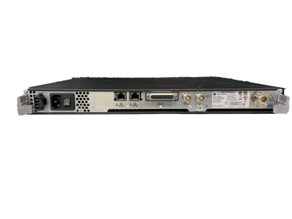
ABZ99FT4097B
Jan 19, 2023Non Broadcast Transmitter
Equipment Class
TNB - Licensed Non-Broadcast Station Transmitter