ADV0602902Scanning Receiver
General Research of Electronics Inc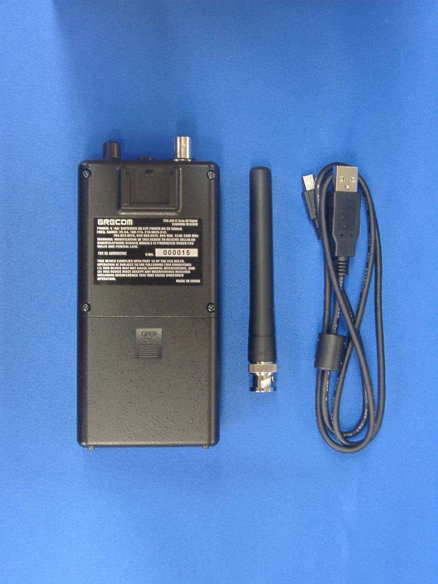
Click to zoom
Application Details
- Equipment Class
- CSR - Scanning Receiver
- Date of Grant
- Jan 27, 2011
- Application Purpose
- Original Equipment
- Date of Application
- Jan 27, 2011
- Equipment Note
- Scanning Receiver
- Frequency Range
- 894.00000000 - 960.00000000
- Country
- Japan
Documents & Files
Document Text
Text extracted from the exhibit documents filed with the FCC. Open a document above to read the original.
Users Manual
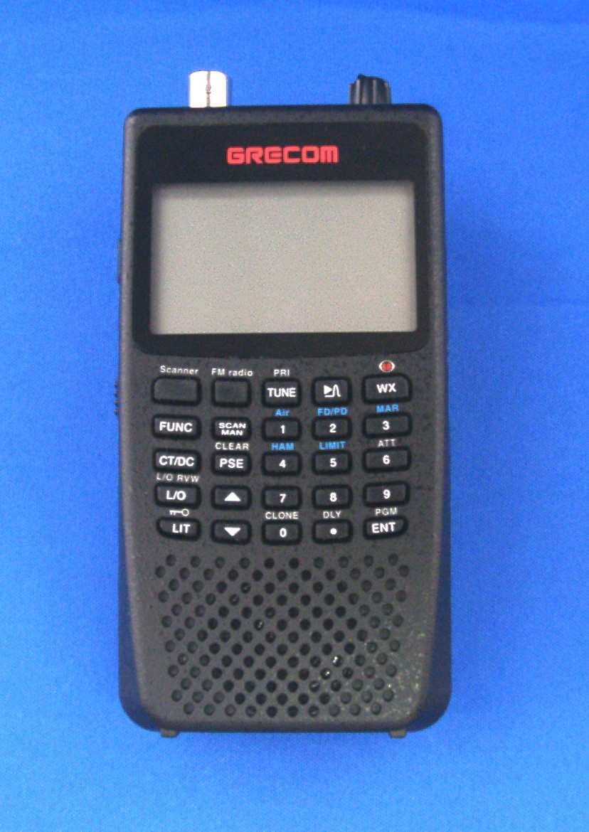
GRECOM PSR-800 EZ Scan-SD Digital Owner’s Manual GRECOM PSR-800 EZ Scan-SD Digital Handheld Scanning Receiver FCC ID ADV0602902 This device complies with part 15 of the FCC Rules. Operation is subject to the following two conditions: (1) This device may not cause harmful interference, and (2) this device must accept any interference received, including interference that may cause undesired operation. Motorola, Smartnet, Smartzone, Omnilink, ASTRO and Privacy Plus are registered trademarks of Motorola Inc. EDACS and ProVoice are registered trademarks of Harris Inc. LTR is a registered trademark of E.F. Johnson, Inc. The IMBE™ voice coding Technology embodied in this product is protected by intellectual property rights including patent rights, copyrights and trade secrets of Digital Voice Systems, Inc. This voice coding Technology is licensed solely for use within this Communications Equipment. The user of this Technology is explicitly prohibited from attempting to decompile, reverse engineer, or disassemble the Object Code, or in any other way convert the Object Code into a human readable form. U.S. Pat. Nos. 5,870,405 and 5,517,511 Copyright © 2011 GRE America, Incorporated All Rights Reserved OWNERʼS MANUAL - Please read before using this equipment. IMPORTANT: This manual uses the following symbols to emphasize Warnings, Notes and Usage Hints WARNING A WARNING symbol is used to indicate possible risk of personal injury or damage to equipment NOTE A NOTE symbol is used to indicate an operational note that relates to the current paragraph of the manual A HINT symbol is used to indicate a usage hint that relates to the current paragraph of the manual HINT IMPORTANT NOTICE: The PSR-800 handheld scanner is designed to receive analog or digital P25 transmissions only, and cannot be used to monitor other unsupported digital modes or encrypted radio traffic. Please take the time to read this manual completely before using your new scanner. Ta b l e o f C o n t e n t s ..........................................................................................................Introduction!5 ...........................................................................................................Features!5 ........................................................................The FCC Wants You To Know!7 ............................................................................................Scanning Legally!8 ...................................................................................How the PSR-800 Works!10 ..............................................................RadioReference Copyright Notice!11 .............................................................Installing the PSR-800 PC Application!12 ................................................................Getting Familiar With Your PSR-800!16 ......................................................................................PSR-800 Front View!16 ..........................................................................Understanding the Keypad!17 ...................................................................................POWER/Backlight !17 ................................................................................................MENU Key!17 ..................................................................................................SKIP Key!17 ....................................................................SCAN/PAUSE/SELECT Key!18 ..........................................................................................UP Arrow Key!18 ....................................................................................DOWN Arrow Key!18 ....................................................................................RIGHT Arrow Key!18 ......................................................................................LEFT Arrow Key!19 ....................................................................................................ATT Key !19 .....................................................................................................WX Key!19 .................................................................Other Switches and Controls!19 ......................................................................Battery Type Selection!19 ...............................................................................................Squelch!20 ..........................................................................Understanding the Display!20 ....................................................................................“psDr” Indicators!22 ...........................................................................................Display Icons!23 ...................................................................................................Getting Started!25 ...............................................................................Unpacking the PSR-800!25 ..................................................................................Inserting the batteries!25 ................................................................Charging rechargeable batteries!26 ............................................................................................Using AC Power!26 .......................................................................Using Vehicle Battery Power!28 ..................................................................................Attaching the antenna!29 ..................................................................................Attaching the belt clip!29 ...............................................................................Turning the PSR-800 on!29 ....................................................................................Low Battery Warning!30 ................................................Connecting an Optional External Antenna!30 ..................................................Connecting an Earphone or Headphones!31 ..................…
Text truncated - open the document above for the full version.
Attestation Statements
Phone: +813-5439-3611 SHIBA NO.3 AMEREX BLDG. 3-12-17 MITA, MINATO-KU TOKYO 108-0073, JAPAN Fax: +813-5439-3644 GENERAL RESEARCH OF ELECTRONICS, INC. November 22, 2010 Federal Communications Commission Authorization and Evaluation Division Laboratory Division 7435 Oakland Mills Road Colombia, MD 21046 Ref.: FCC ID: ADV0602902 This is to clarify that the above equipment is incapable of operating (tuning) or readily being altered by the user to operate, within the frequency bands to the Cellular Radiotelephone Service. The frequencies in question are deleted from the ROM during manufacture, and cannot be restored through any readily available process or component such as: installation of cuts, jumper wires, resistors, diodes, or plug-in IC’s; deletion of such items; or reprogramming via access codes or external devices such as a personal computer. The receiver is incapable of converting digital cellular transmissions to analog voice audio. Assessing the vulnerability of the receiver to possible modification The receiver has the possibility of reducing the threshold value to discern transmissions from the Cellular Radiotelephone Service by making modification such as adding jumper wire to the UHF RF tuning circuit and UHF mixer circuit. Design features that prevent modification of the receiver to receive Cellular Service The scanning receiver is designed to prevent any attempt for the user to modify the receiver to receive transmissions from the Cellular Radiotelephone Service by using epoxy to cover the required parts of the UHF RF tuning circuit. PRODUCT DEVELOPMENT & MANUFACTURING GENERAL RESEARCH OF ELECTRONICS, INC. Testing method used to determine compliance with the 38 dB rejection ratio Test set-up: Equipment Setup Block Diagram Test Test frequencies: 869.00MHz, 877.03MHz, 885.06MHz, 893.09MHz easurement method (1) o perform initial screening, adjust EUT’s for the Squelched Threshold to suppress audio output. quelch Threshold sensitivity of -6 dBuV.) This is approximately 66-38=28dB above the FCC limit.) (3) Turn EUT on and search cellular frequencies on all of the receiving ranges. (4) List all detected frequencies if EUT detects any. (5) Reprocedure for each of the other cellular test frequencies. (6) To determine actual image rejection ratio for a detected frequency, perform the following steps. (7) Set both of EUT and SSG’s frequency to the frequency gained by the above screening. INAD and record the gained level. Note the gained SG’s level is EUT‘s receiving sensitivity. conditions: AF Signal : 1 kHz FM Deviation : +/- 3kHz AM Modulation : 60 % 824.00MHz, 832.03MHz, 840.06MHz, 848.09MHz M T (2) Set SSG’s frequency to a cellular band test frequency and apply 60dBuV RF level to EUT. (The 60dBuV signal level corresponds to approximately 66dB above the S eat the above p (8) Adjust SSG’s RF output on EUT for 12dB S S
External Photos
External EUT Photos ADV0602902
ID Label/Location Info
PSR-800 EZ Scan-SD Digital SCANNING RECEIVER FCC ID: ADV0602902 POWER: 4 "AA" BATTERIES OR EXT POWER DC 5V 500mA FREQ. RANGE: 25-54, 108-174, 216.0025-512, 764-823.9875, 849-868.9875, 894-960, 1240-1300 MHz MADE IN CHINA WARNING: MODIFICATION OF THIS DEVICE TO RECEIVE CELLULAR RADIOTELEPHONE SERVICE SIGNALS IS PROHIBITED UNDER FCC RULES AND FEDERAL LAW. THIS DEVICE COMPLIES WITH PART 15 OF THE FCC RULES. OPERATION IS SUBJECT TO THE FOLLOWING TWO CONDITIONS: (1) THIS DEVICE MAY NOT CAUSE HARMFUL INTERFERENCE, AND (2) THIS DEVICE MUST ACCEPT ANY INTERFERENCE RECEIVED INCLUDING INTERFERENCE THAT MAY CAUSE UNDESIRED OPERATION. S/NO. 50.5mm 31.5mm 4-R2 REMARKS 1. MATERIAL: PLASTIC FOIL (0.1+0.03mm) 2. FINISH: BLACK BASE/SILVER LETTERS MATT COATING #0602902 (PSR-800/EZ SCAN-SD Digital) MODEL LABEL AUG. 19 2010 Nov. 19 2010 GR-10D-2320 S. Yamamoto M. Ishizuka Tolerance: -0.5mm SHEET DRAWING No. REVISION DRAWN APPRVD Signature Signature Date Date TITLE GENERAL RESEARCH OF ELECTRONICS, INC. A B C Revision Note Date Changed by Date Approved by Rev. No. TOLERANCE ABCD ANGLE CLASS DIVISION ≦5 5< ≦20 20< ≦50 50< ≦100 100< 0.05 0.1 0.15 0.2 0.3 0.20 0.1 0.15 0.2 0.3 0.4 0.40 0.15 0.2 0.3 0.4 0.5 1.5 0.2 0.3 0.4 0.5 0.6 3
ID Label/Location Info
ADV0602902 MODEL LABEL LOCATION The §15.19(a)(3) statement GENERAL RESEARCH OF ELECTRONICS,INC. FCC ID NO. WARNING RATING LABEL This device complies with Part 15 of the FCC Rules. Operation is subject to the following two conditions: (1) This device may not cause harmful interference, and (2) This device must accept any interference received, including interference that may cause undesired operation. OPEN
Parts List/Tune Up Info
GENERAL RESEARCH OF ELECTRONICS, INC. FCC ID: ADV0602902 FUNCTION OF EACH SEMICONDUCTOR OR OTHER ACTIVE CIRCUIT DEVICE [2.983(6)] 1. Transistor, FET Q1DTA114EUASWITCHING Q2UMD2NSWITCHING Q32SC4094(R37) or 2SC4094(R38)RF AMP Q42SC4226(R25)RF AMP Q5DTC114YUA or UN5214SWITCHING Q6UMD2NSWITCHING Q72SC4094(R37) or 2SC4094(R38)RF AMP Q82SC4116(Y)AGC AMP Q92SC42502nd MIXER Q102SC4215(O)2nd IF AMP Q112SC4116(GR)AGC AMP Q12DTC114YUA or UN5214SWITCHING Q13DTC114YUA or UN5214SWITCHING Q14DTC114YUA or UN5214SWITCHING Q152SC4215(O) or 2SC4226(R25)2nd IF AMP Q162SC4215(O) or 2SC4226(R25)2nd IF AMP Q17DTA114EUASWITCHING Q18DTC114YUA or UN5214SWITCHING Q192SC4226(R25)SWITCHING Q202SC4226(R25)VCO 1 Q21DTC114YUA or UN5214SWITCHING Q222SC4226(R25)VCO 2 Q23DTC114YUA or UN5214SWITCHING Q242SC4226(R25)BUFFER VCO 1&2 Q252SC4116(GR)LOW PASS FILTER Q262SK880(Y)LOW PASS FILTER Q272SK880(Y)LOW PASS FILTER Q282SC4116(GR)LOW PASS FILTER Q292SC4251 or MT3S16U or KTC4082/PVCO 3 Q302SC4250 or 2SC4251 BUFFER VCO 3 /or MT3S16U or KTC4082/P Q31DTA114EUAFILTER SWITCHING Q322SD2150T100RMuting Q33EMD12SWITCHING Q34EMD12SWITCHING Q35SSM3K101TUSWITCHING Q301DTC114YUASWITCHING Q3022SA1577(Q)LED DRIVER Q3032SA1577(Q)LED DRIVER Q3042SC4116(GR)LED DRIVER Q3052SC4116(GR)RESET SWITCH Q3062SC4116(GR)LED DRIVER Q3072SC4116(GR)LED DRIVER Q308SSM3K101TUSWITCHING Q309SSM6J53FESWITCHING Q310SSM6J53FESWITCHING Q311DTC114YUASWITCHING Q312DTC114YUASWITCHING Q3132SC4117(GR)SWITCHING Q3142SB1412SWITCHING Q3152SC4116(GR)SWITCHING Q3162SC4116(GR)LED DRIVER Q317SSM6J53FEPOWER SWITCHING Q318SSM6J53FEPOWER SWITCHING Q3192SC4116(GR)POWER SWITCHING GENERAL RESEARCH OF ELECTRONICS, INC. FCC ID: ADV0602902 FUNCTION OF EACH SEMICONDUCTOR OR OTHER ACTIVE CIRCUIT DEVICE [2.983(6)] 2. IC IC1HD74AC164BAND SELECT/ATT.CONT. or TC74VHC164 IC2uPC2757TB1st MIXER IC3NJM2406DETECTOR COMPARATOR IC4MB15F07SLPLL IC5TK11819MDC TO DC CONVERTOR IC6NJM2904MCOMPARATOR / NOISE AMP IC7TK10931V3rd IF AMP / 3rd LO / 3rd MIX / NOISE AMP / QUADRATURE DETECTOR IC8NJM13403VBUFFER/PRE AMP IC9TC74HC4066AFTSWITCHING IC10TC4S66FSWITCHING IC11TK11233CUCBVOLTAGE REGULATOR IC12NJU7086FR3AUDIO AMP IC13TC7W66FUSWITCHING IC14TC4S66FSWITCHING IC301M30626FHPGP#U5CCPU (GRE-0602902) IC302S-1206B18-M3T1GVOLTAGE REGULATOR IC303NOT USED IC304BA033CC0FPVOLTAGE REGULATOR IC305S-1206B14-M3T1GVOLTAGE REGULATOR IC306TLV320AIC14KIDBTRCODEC IC307S-1206B33-U3T1GVOLTAGE REGULATOR IC308BD8311NUVSW REGULATOR IC309TMS320VC5507PGEDSP IC310PIC18F46J50I/PTPIC MICON
Test Report
EMC Report for General Research of Electronics, Inc. on the model ADV0602902 100284613MPK-001 Page 1 of 20 TEST REPORT Report Number: 100284613MPK-001 Project Number: 100284613 December 29, 2010 Testing performed on the Scanning Receiver Model Number: ADV0602902 FCC ID: ADV0602902 to FCC Part 15, Subpart B Class: B for GRE America Test Performed by: Test Authorized by: Intertek 1365 Adams Court Menlo Park, CA 94025 USA GRE America 425 Harbor Blvd. Suite B Belmont, CA 94002 USA Prepared by: Date: December 29, 2010 Ollie Moyrong Reviewed by: Date: December 29, 2010 Krishna K Vemuri This report is for the exclusive use of Intertek's Client and is provided pursuant to the agreement between Intertek and its Client. Intertek's responsibility and liability are limited to the terms and conditions of the agreement. Intertek assumes no liability to any party, other than to the Client in accordance with the agreement, for any loss, expense or damage occasioned by the use of this report. Only the Client is authorized to copy or distribute this report and then only in its entirety. Any use of the Intertek name or one of its marks for the sale or advertisement of the tested material, product or service must first be approved in writing by Intertek. The observations and test results in this report are relevant only to the sample tested. This report by itself does not imply that the material, product, or service is or has ever been under an Intertek certification program. This report must not be used to claim product endorsement by A2LA, NIST nor any other agency of the U.S. Government. EMC Report for General Research of Electronics, Inc. on the model ADV0602902 100284613MPK-001 Page 2 of 20 VERIFICATION OF COMPLIANCE Report No. 100284613MPK-001 Verification is hereby issued to the named APPLICANT and is VALID ONLY for the equipment identified hereon for use under the rules and regulations listed below. Equipment Under Test: Scanning Receiver Trade Name: GRE America Model No.: ADV0602902 Serial No. 000015 Applicant: GRE America Contact: Mr. Raj Gounder Address: 425 Harbor Blvd. Suite B Belmont, CA 94002 Country USA Tel. number: 650-591-1400 Fax number: 650-591-2001 Applicable Regulation: FCC Part 15, Subpart B Equipment Class: Class B Date of Test: December 20, 2010 We attest to the accuracy of this report: Ollie Moyrong Engineering Manager Krishna Vemuri Senior Staff EMC Engineer EMC Report for General Research of Electronics, Inc. on the model ADV0602902 100284613MPK-001 Page 3 of 20 TABLE OF CONTENTS 1.0 General Description ........................................................................................................ 4 1.1....... Product Description ........................................................................................................ 4 1.2....... Related Submittal(s) Grants ............................................................................................ 4 1.3....... Test Methodology ........................................................................................................... 4 1.4....... Test Facility .................................................................................................................... 4 1.5....... Summary of Test Results ................................................................................................ 5 2.0 System Test Configuration............................................................................................. 6 2.1....... Justification ..................................................................................................................... 6 2.2....... EUT Exercising Software ............................................................................................... 6 2.3....... Mode of Operation.......................................................................................................... 6 2.4....... Support Equipment List and Description........................................................................ 7 2.5....... Equipment Setup Block Diagram ................................................................................... 7 2.6....... Equipment Modification ................................................................................................. 7 3.0 Emission Test Results ..................................................................................................... 8 3.1....... Field Strength Calculation .............................................................................................. 9 3.2....... Radiated Emission Data................................................................................................ 10 3.3....... AC Line Conducted Emission Data .............................................................................. 14 3.4....... Antenna Conducted Emission Data .............................................................................. 15 4.0 List of Test Equipment ................................................................................................. 18 Appendix A – Local Oscillator Frequency Calculation......................................................... 19 Appendix B – ADV0602902 Specification............................................................................... 20 EMC Report for General Research of Electronics, Inc. on the model ADV0602902 100284613MPK-001 Page 4 of 20 1.0 General Description 1.1 Product Description The Equipment Under Test (EUT) is a Digital Scanning Receiver, model ADV0602902. Refer to the attached specifications sheets in Appendix B for more details. A production version of the sample was received on December 19, 2010 in good condition. As declared by the Applicant, it is identical to production units. 1.2 Related Submittal(s) Grants This is a single application for certification of a scanning receiver. 1.3 Test Methodology Both conducted (if applicable) and radiated emission measurements were performed according to the procedures in ANSI C63.4. …
Text truncated - open the document above for the full version.
Test Setup Photos
Test Setup Photos ADV0602902
Contact Information
Applicant
Sadanori Shitara(Director of Engineering and Development)
Technical Contact
Intertek Testing Services NA, Inc.Krishna Vemuri
[email protected]650-463-4644
1365 Adams Ct. · Menlo Park, California · United States
Non-Technical Contact
General Research of Electronics IncRaj Gounder
[email protected]650 591-1400
Test Firm
Intertek Testing Services NA Inc.John Quigley
Technical Specifications
| # | Rule Parts | Frequency Range | Power Output |
|---|---|---|---|
| 1 | 15B | 894 MHz - 960 MHz | - |
Other Applications from General Research of Electronics Inc
ADV0908900
Apr 03, 2012Scanning Receiver
Equipment Class
CSR - Scanning Receiver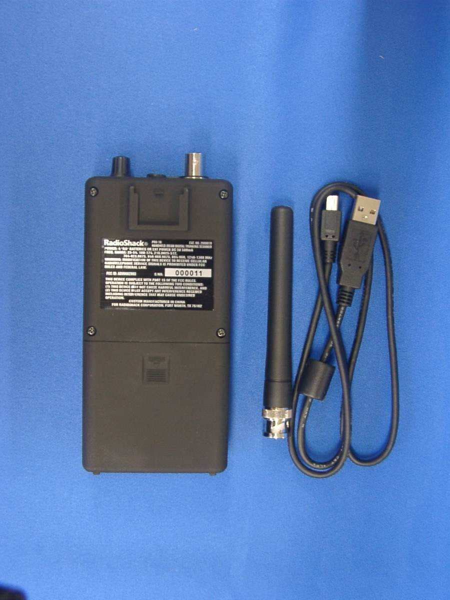
ADV0602903
Jan 27, 2011Scanning Receiver
Equipment Class
CSR - Scanning Receiver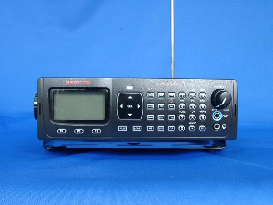
ADV0714902
Jan 16, 2011Radio Frequency Scanner
Equipment Class
CSR - Scanning Receiver
ADV0713902
Aug 12, 2010Radio Frequency Scanner
Equipment Class
CSR - Scanning Receiver
ADV0704
Jun 02, 2010Scanning Receiver
Equipment Class
CSR - Scanning Receiver