ADV0713902Radio Frequency Scanner
General Research of Electronics Inc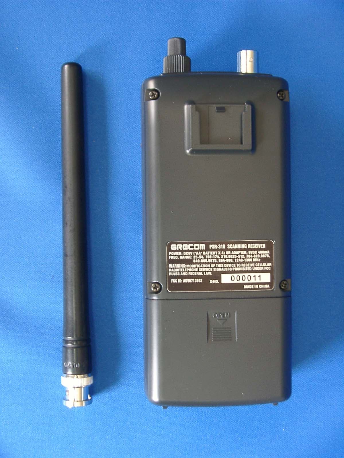
Click to zoom
Application Details
- Equipment Class
- CSR - Scanning Receiver
- Date of Grant
- Aug 12, 2010
- Application Purpose
- Original Equipment
- Date of Application
- Aug 12, 2010
- Equipment Note
- Radio Frequency Scanner
- Frequency Range
- 894.00000000 - 960.00000000
- Country
- Japan
Documents & Files
Document Text
Text extracted from the exhibit documents filed with the FCC. Open a document above to read the original.
Users Manual
PSR-310 Advanced Handheld Scanning Receiver with Object Oriented User Interface Owner's Manual Please read this User's Guide before installing, setting up and using your new product. Table of Contents will add Introduction Welcome to an exciting new world of radio scanning! Recognizing that contemporary scanning receivers are too hard to program and use, GRE's engineers conducted extensive research to determine the functional requirements for an entirely new scanning receiver user interface. We call this new user interface the Object Oriented User Interface (OOUI), and it is based on the premise that, to a hobbyist, a scanner is easiest to use if all of the things that can be scanned are handled using common conventions for interaction between the user and the radio, at least to the extent that this is possible given that the ”things” that can be scanned are different from one another in either subtle or major ways. In this new user interface design, we call “things” that can be scanned Scannable Objects. Simply put, a Scannable Object is defined as something that can be scanned or monitored. Scannable Objects include the following: . Conventional, non-trunked radio channels . Trunked talkgroups used on a trunked radio system . Service searches to search for a specific radio service . Search ranges with upper and lower limits . Spectrum Sweeper setups with band segments that can be enabled or disabled by the user One of the goals of the Object Oriented User Interface is to make the scanner as easy to use as possible. The OOUI does this by treating all Scannable Objects the same in terms of how they are created, edited, manipulated and grouped. Once you have learned how to create and store a conventional channel, you know most of what you need to know to create a trunking talkgroup, and so on. While we have designed this radio to be the easiest scanning receiver in its class to program and use, we encourage you to read this manual in its entirety so that you will fully understand all of the radio's capabilities. However, if you consider yourself to be an experienced scanning hobbyist and are feeling adventurous, we invite you to dive right in and get started programming your favorite “objects” into the radio. Features Upgradeable CPU Firmware - keep your radio current with enhancements as they become available with free upgrades from www.greamerica.com! Intuitive "Object Oriented" User Interface Design is designed for ease of use, yet powerful enough to satisfy the most sophisticated experts. Common data entry, browsing and control methods are used for non-trunked conventional channels, trunking talkgroups, search configurations and Spectrum Sweeper setups. The radio grows with you - you can start out with a small, easy to manage configuration, then expand it whenever you need to. Menu Driven Programming With Context Sensitive Help - Each menu item provides a few lines of help text that provide assistance with programming and using the scanner. Powerful and flexible Scan List functionality - allows you to arrange, group and scan objects according to your preference. Flexible Free-Form Memory Organization - memory is assigned as objects are created using a sophisticated internal file management system. You are not constrained to traditional bank/channel scanner memory layouts. No memory is wasted as a result of bank/channel programming constraints. The scanner has sufficient main memory capacity to store over 1,800 conventional channels, trunking talkgroups, search configurations and Spectrum Sweeper objects in any combination, providing ample capacity for more sophisticated hobbyists and professionals while keeping the database size manageable for beginners. SKYWARN Storm Spotter Functionality - Instant access to frequencies used by storm spotter networks. You can monitor storm conditions as they occur, and become aware of dangerous conditions before the media or emergency management officials are able to announce them to the general public. SAME and All Hazards Weather Alerting - Your scanner can operate in dedicated Specific Area Message Encoding (SAME) weather alerting mode, and alert you to severe weather and other hazards in the specific area(s) that you select, or, your scanner can check your local NOAA weather frequency periodically, even while scanning and alert you when an All Hazards alert occurs. Multi-System Trunking - Scans most common trunked radio system signaling formats, including Motorola, EDACS, and LTR trunked radio networks. Both talkgroup and individual call monitoring are supported. GRE's Exclusive Digital AGC - instantly compensates for low user audio levels that are very common on digital systems. This makes the radio easier to listen to, and provides you with a more enjoyable scanning experience. LTR Home Repeater AutoMove - Takes the guesswork out of programming LTR trunking systems when the home repeater order is not known. Enter the LTR system frequencies in any order, and the PSR-310 will automatically move the frequencies to the proper home repeater slots as transmissions are received on the system. The Best Subaudible Squelch Decoder in the Scanning Industry - CTCSS and DCS subaudible squelch coding is processed by the CPU. Provides fast and reliable decoding of subaudible squelch signaling with squelch tail elimination. Powerful Spectrum Sweeper - Quickly sweeps the scanner's frequency ranges for transmissions from nearby sources. When a nearby active frequency is found, the scanner automatically tunes to that frequency and receives the traffic. Exclusive ALERT LED - Programmable tri-color LED can be configured to illuminate or flash when certain objects are active. Eight user-defined colors and brightness levels can be specified from thousands of possible combinations. Provides visual alerts when certain channels are active, e.g., blue can be used to signal activity on your primary police channel, red for fire, etc. Audible alarms - Programmable audible a…
Text truncated - open the document above for the full version.
Attestation Statements
Phone: +813-5439-3611 SHIBA NO.3 AMEREX BLDG. 3-12-17 MITA, MINATO-KU TOKYO 108-0073, JAPAN Fax: +813-5439-3644 GENERAL RESEARCH OF ELECTRONICS, INC. May 27, 2010 Federal Communications Commission Authorization and Evaluation Division Laboratory Division 7435 Oakland Mills Road Colombia, MD 21046 Ref.: FCC ID: ADV0713902 This is to clarify that the above equipment is incapable of operating (tuning) or readily being altered by the user to operate, within the frequency bands to the Cellular Radiotelephone Service. The frequencies in question are deleted from the ROM during manufacture, and cannot be restored through any readily available process or component such as: installation of cuts, jumper wires, resistors, diodes, or plug-in IC’s; deletion of such items; or reprogramming via access codes or external devices such as a personal computer. The receiver is incapable of converting digital cellular transmissions to analog voice audio. Assessing the vulnerability of the receiver to possible modification The receiver has the possibility of reducing the threshold value to discern transmissions from the Cellular Radiotelephone Service by making modification such as adding jumper wire to the UHF RF tuning circuit and UHF mixer circuit. Design features that prevent modification of the receiver to receive Cellular Service The scanning receiver is designed to prevent any attempt for the user to modify the receiver to receive transmissions from the Cellular Radiotelephone Service by using epoxy to cover the required parts of the UHF RF tuning circuit. PRODUCT DEVELOPMENT & MANUFACTURING GENERAL RESEARCH OF ELECTRONICS, INC. Testing method used to determine compliance with the 38 dB rejection ratio Test set-up: Equipment Setup Block Diagram Test Test frequencies: 869.00MHz, 877.03MHz, 885.06MHz, 893.09MHz easurement method (1) o perform initial screening, adjust EUT’s for the Squelched Threshold to suppress audio output. quelch Threshold sensitivity of -6 dBuV.) This is approximately 66-38=28dB above the FCC limit.) (3) Turn EUT on and search cellular frequencies on all of the receiving ranges. (4) List all detected frequencies if EUT detects any. (5) Reprocedure for each of the other cellular test frequencies. (6) To determine actual image rejection ratio for a detected frequency, perform the following steps. (7) Set both of EUT and SSG’s frequency to the frequency gained by the above screening. INAD and record the gained level. Note the gained SSG’s level is EUT‘s receiving sensitivity. conditions: AF Signal : 1 kHz FM Deviation : +/- 3kHz AM Modulation : 60 % 824.00MHz, 832.03MHz, 840.06MHz, 848.09MHz M T (2) Set SSG’s frequency to a cellular band test frequency and apply 60dBuV RF level to EUT. (The 60dBuV signal level corresponds to approximately 66dB above the S eat the above p (8) Adjust SSG’s RF output on EUT for 12dB S
Parts List/Tune Up Info
GENERAL RESEARCH OF ELECTRONICS, INC. FCC ID: ADV0713902 FUNCTION OF EACH SEMICONDUCTOR OR OTHER ACTIVE CIRCUIT DEVICE [2.983(6)] 1. Transistor, FET Q1 DTA114EUASWITCHING Q2 UMD2NSWITCHING Q3 2SC4094(R37) or 2SC4094(R38) RF AMP Q4 2SC4226(R25)RF AMP Q5 DTC114YUA or UN5214SWITCHING Q6 UMD2NSWITCHING Q7 2SC4094(R37) or 2SC4094(R38) RF AMP Q8 2SC4116(Y)AGC AMP Q9 2SC42502nd MIXER Q10 2SC4215(O)2nd IF AMP Q11 2SC4116(GR)AGC AMP Q12 DTC114YUA or UN5214SWITCHING Q13 DTC114YUA or UN5214SWITCHING Q14 DTC114YUA or UN5214SWITCHING Q15 2SC4226(R25)2nd IF AMP Q16 2SC4226(R25)2nd IF AMP Q17 DTA114EUASWITCHING Q18 DTC114YUA or UN5214SWITCHING Q19 2SC4226(R25)SWITCHING Q20 2SC4226(R25)VCO 1 Q21 DTC114YUA or UN5214SWITCHING Q22 2SC4226(R25)VCO 2 Q23 DTC114YUA or UN5214SWITCHING Q24 2SC4226(R25)BUFFER VCO 1&2 Q25 2SC4116(GR)LOW PASS FILTER Q26 2SK880(Y)LOW PASS FILTER Q27 2SK880(Y)LOW PASS FILTER Q28 2SC4116(GR)LOW PASS FILTER Q29 2SC4251 or MT3S16UVCO 3 Q30 2SC4250 or 2SC4251BUFFER VCO 3 or MT3S16U or KTC4082 Q31 DTA114EUAFILTER SWITCHING Q32 DTC114YUA or UN5214Muting Q33 DTC114YUA or UN5214SWITCHING Q34 2SD2118CHARGE CIRCUIT Q35 2SC4117(GR)CHARGE CIRCUIT Q301 2SA1577(Q)LCD DRIVER Q302 2SA1577(Q)LCD DRIVER Q303 DTC114YUA or UN5214SWITCHING Q304 2SC4116(GR)LCD DRIVER Q305 2SC4116(GR)LCD DRIVER Q306 2SC4116(GR)RESET CIRCUIT Q307 2SC4116(GR)LCD DRIVER GENERAL RESEARCH OF ELECTRONICS, INC. FCC ID: ADV0713902 FUNCTION OF EACH SEMICONDUCTOR OR OTHER ACTIVE CIRCUIT DEVICE [2.983(6)] 2. IC IC1 HD74AC164BAND SELECT/ATT.CONT. or TC74VHC164 IC2 uPC2757TB1st MIXER IC3 NJM2406DETECTOR COMPARATOR IC4 Not used IC5 MB15F07SLPLL IC6 TK11819MDC TO DC CONVERTOR IC7 NJM2904MCOMPARATOR / NOISE AMP IC8 TK10931V3rd IF AMP / 3rd LO / 3rd MIX / NOISE AMP / QUADRATURE DETECTOR IC9 NJM13404VBUFFER/PRE AMP IC10 TC4S66FSWITCHING IC11 TC74HC4066AFTSWITCHING or TC74HC4066AFS or U74HCT4066L IC12 BA05FP or BA05CC0FP VOLTAGE REGULATOR IC13 NJM2070MAUDIO AMP IC14 AN77033SPVOLTAGE REGULATOR or BA033CC0FP IC15 TK11233CUCBVOLTAGE REGULATOR IC301 HN58X24512FPIMEMORY or M24512WMW6T or M24512WMW6TG IC302 TK11233CUCBVOLTAGE REGULATOR or TK11233BUCB IC303 NJM13403VLOW SPEED DATA FILTER IC304 NJM2903MHI SPEED DATA FILTER / LOW SPEED DATA FILTER IC305 S-80820CNNBVOLTAGE DETECTOR or S-80820ANNP IC306 NJM13403VSAME DATA FILTER / WX ALERT DATA FILTER IC307 M3062LFGPGP#U5C CPU (GRE-713902)
RF Exposure Info
FCC ID: ADV0713902 1 LOCAL OSC FREQUENCY CALCULATION -1 FCC ID: ADV0713902 formula for 1st, 2nd and 3rd Local oscillation frequencies are as follow : RECEIVINGFREQ.RECEIVING FREQ. 1st LOCAL2nd LOCAL 3rd LOCAL BANDSTEP FR (MHz)PLL 1 /VCO 1 or VCO 2PLL 2 /VCO 3 X' TAL (FR STEP)( kHz ) (MHz)(MHz) (MHz) VHF Low10 25.0000 ~ 27.4050 A = (FR + 380.800) / 0.0752nd Local = 1st IF - 21.420.9450 5 27.4100 ~ 29.7000 = A.xxx (Cut away decimal) 10 29.7100 ~ 49.8300 1st Local = A x 0.075 5 49.8350 ~ 54.0000 1st IF = 1st Local - FR VHF High8.33 108.0000 ~ 136.991662nd Local = 1st IF - 21.420.9450 5 137.0000 ~ 137.9950 12.5 138.0000 ~ 143.9875 5 144.0000 ~ 147.9950FR DENOTES Frequency Received. 12.5 148.0000 ~ 150.7875 5 150.8000 ~ 150.8450 7.5 150.8525 ~ 154.4975 5 154.5150 ~ 154.6400 7.5 154.6500 ~ 156.2550 25 156.2750 ~ 157.4500 7.5 157.4700 ~ 161.5725 5 161.6000 ~ 161.9750 12.5 162.0000 ~ 174.0000 5 216.0025 ~ 224.9950 UHF Low6.25 225.0000 ~ 316.543752nd Local = 1st IF - 21.420.9450 〃 316.5500 ~ 316.79375A = (FR + 380.700) / 0.075 〃 316.8000 ~ 337.89375A = (FR + 380.800) / 0.075 〃 337.9000 ~ 338.09375A = (FR + 380.700) / 0.075 〃 338.1000 ~ 359.29375A = (FR + 380.800) / 0.075 〃 359.3000 ~ 359.49375A = (FR + 380.700) / 0.075 〃 359.5000 ~ 379.99375A = (FR + 380.800) / 0.075 12.5 380.0000 ~ 380.7125〃 〃 380.7250 ~ 380.8000A = (FR + 380.700) / 0.075 〃 380.8125 ~ 400.0000A = (FR + 380.800) / 0.075 〃 400.0125 ~ 405.9750A = (FR + 380.700) / 0.075 〃 405.9875 ~ 419.9875A = (FR + 380.800) / 0.075 5 420.0000 ~ 450.0000〃 6.25 450.00625 ~ 469.99375〃 6.25 470.0000 ~ 512.0000〃 UHF High3.125 764.0000 ~ 781.996875 A = (FR - 380.800) / 0.0752nd Local = 1st IF - 21.420.9450 〃 791.0000 ~ 796.996875 = A.xxx (Cut away decimal) 12.5 806.0000 ~ 823.9875 1st Local = A x 0.075 〃 849.0000 ~ 868.9875 1st IF = FR - 1st Local 〃 894.0000 ~ 939.9875 6.25 940.0000 ~ 960.0000 〃 1240.0000 ~ 1300.0000 6517.333 -2 IF FREQUENCY 1st IF : 380.6500 ~ 380.86875Hz 2nd IF : 21.4000MHz 3rd IF : 455kHZ -3 Example RECEIVINGFREQ.RECEIVING FREQ. 1st LOCAL2nd LOCAL 3rd LOCAL BANDSTEP FR (MHz)PLL 1 /VCO 1 or VCO 2PLL 2 /VCO 3 X' TAL (FR STEP)( kHz ) (MHz)(MHz) (MHz) VHF Low5.025.0000 A : 5410.666 = (25.0000 + 380.800) / 0.075 359.350 = 380.750 - 21.420.9450 = 5410.666 (Cut away decimal) 1st Local : 405.750 =5410 x 0.075 1st IF : 380.750 = 405.750 - 25.0000 10.041.0000 5624.000 = (41.0000 + 380.800) / 0.075 359.400 = 380.800 - 21.420.9450 = 5624.000 (Cut away decimal) 421.800 =5624 x 0.075 380.800 = 421.800 - 41.0000 5.054.0000 5797.333 = (54.0000 + 380.800) / 0.075 359.375 = 380.775 - 21.420.9450 = 5797.333 (Cut away decimal) 434.775 =5797 x 0.075 380.775 = 434.775 - 54.0000 VHF High8.33108.0000 6517.333 = (108.0000 + 380.800) / 0.075 359.375 = 380.775 - 21.420.9450 = 6517.333 (Cut away decimal) (Cutawaydecimal) 488.775 =6517 x 0.075 380.775 = 488.775 - 108.0000 5.0137.0000 6904.000 = (137.0000 + 380.800) / 0.075 359.400 = 380.800 - 21.420.9450 = 6904.000 (Cut away decimal) 517.800 =6904 x 0.075 380.800 = 517.800 - 137.0000 7.5154.1000 7132 = (154.1000 + 380.800) / 0.075 359.400 = 380.800 - 21.420.9450 = 7132 (Cut away decimal) 534.9 =7132 x 0.075 380.800 = 534.900 - 154.1000 12.5174.0000 7397.333 = (174.0000 + 380.800) / 0.075 359.375 = 380.775 - 21.420.9450 = 7397.333 (Cut away decimal) 554.775 = 7397 x 0.075 380.775 = 554.775 - 174.0000 5.0216.0025 7957.366 = (216.0025 + 380.800) / 0.075 359.3725 = 380.7725 - 21.420.9450 = 7957.366 (Cut away decimal) 596.775 = 7957 x 0.075 380.7725 = 596.775 - 216.0025 12.5806.00005669.333=(806.0000380.800)/0.075359.425=380.82521.420.9450 RECEIVINGFREQ.RECEIVING FREQ. 1st LOCAL2nd LOCAL 3rd LOCAL BANDSTEP FR (MHz)PLL 1 /VCO 1 or VCO 2PLL 2 /VCO 3 X' TAL (FR STEP)( kHz ) (MHz)(MHz) (MHz) UHF Low6.25310.0000 9210.666 = (310.0000 + 380.800) / 0.075 359.350 = 380.750 - 21.420.9450 = 9210.666 (Cut away decimal) 690.750 =9210 x 0.075 380.750 = 690.750 - 310.0000 12.5406.0000 10490.666 = (406.0000 + 380.800) / 0.075 359.350 = 380.750 - 21.420.9450 = 10490.666 (Cut away decimal) 786.750 =10490 x 0.075 380.750 = 786.750 - 406.0000 5.0450.0000 11077.333 = (450.0000 + 380.800) / 0.075 359.375 = 380.775 - 21.420.9450 = 11077.333 (Cut away decimal) 830.775 =11077 x 0.075 380.775 = 830.775 - 450.0000 6.25512.0000 11904.000 = (512.0000 + 380.800) / 0.075 359.400 = 380.800 - 21.420.9450 = 11904.000 (Cut away decimal) 892.800 =11904 x 0.075 380.800 = 892.800 - 512.0000 UHF High3.125764.0000 5109.333 = (764.0000 - 380.800) / 0.075 359.425 = 380.825 - 21.420.9450 = 5109.333 (Cut away decimal) 383.175 =5109 x 0.075 380.825 = 764.000 - 383.175 12.5806.00005669.333=(806.0000-380.800)/0.075 359.425=380.825-21.4 20.9450 = 5669.333 (Cut away decimal) 425.175 =5669 x 0.075 380.825 = 806.000 - 425.175 12.5860.0000 6389.333 = (860.0000 - 380.800) / 0.075 359.425 = 380.825 - 21.420.9450 = 6389.333 (Cut away decimal) 479.175 =6389 x 0.075 380.825 = 860.000 - 479.175 6.25960.0000 7722.666 = (960.0000 - 380.800) / 0.075 359.450 = 380.850 - 21.420.9450 = 7722.666 (Cut away decimal) 579.150 =7722 x 0.075 380.850 = 960.000 - 579.150 6.2512400.0000 11456.000 = (1240.0000 - 380.800) / 0.075 359.400 = 380.800 - 21.420.9450 = 11456.000 (Cut away decimal) 859.200 =11456 x 0.075 380.800 = 1240.000 - 859.200 6.251300.0000 12256.000 = (1300.0000 - 380.800) / 0.075 359.400 = 380.800 - 21.420.9450 = 12256.000 (Cut away decimal) 919.200 =12256 x 0.075 380.800 = 1300.000 - 919.200
Test Report
MET Laboratories, Inc. Safety Certification - EMI - Telecom Environmental Simulation 914 WEST PATAPSCO AVENUE ● BALTIMORE, MARYLAND 21230-3432 ● PHONE (410) 354-3300 ● FAX (410) 354-3313 33439 WESTERN AVENUE ● UNION CITY, CALIFORNIA 94587-3201 ● PHONE (510) 489-6300 ● FAX (510) 489-6372 3162 BELICK STREET ● SANTA CLARA, CA 95054-2401 ● PHONE (408) 748-3585 ● FAX (510) 489-6372 The Nation’s First Licensed Nationally Recognized Testing Laboratory July 20, 2010 GRE America, Inc 425 Harbor Blvd, Suite B Belmont, CA 94002 Dear Francisco Villaherrera, Enclosed is the EMC test report for compliance testing of the GRE America, Inc, PSR-310, tested to the requirements of Title 47 of the Code of Federal Regulations (CFR), Part 15 Subpart B for a Class B Digital Device. Thank you for using the services of MET Laboratories, Inc. If you have any questions regarding these results or if MET can be of further service to you, please feel free to contact me. Sincerely yours, MET LABORATORIES, INC. Sofia Cordova Documentation Department Reference: (\GRE America, Inc\EMCS82452-FCC) Certificates and reports shall not be reproduced except in full, without the written permission of MET Laboratories, Inc. While use of the National Voluntary Laboratory Accreditation Program (NVLAP) letters, the NVLAP Logo, or the A2LA logo in this report reflects MET accreditation under these programs, the report must not be used by the client to claim product certification, approval, or endorsement by NVLAP, NIST, or A2LA, or any agency of the Federal Government. This letter of transmittal is not a part of the attached report. MET Laboratories, Inc. Safety Certification - EMI - Telecom Environmental Simulation 914 WEST PATAPSCO AVENUE ● BALTIMORE, MARYLAND 21230-3432 ● PHONE (410) 354-3300 ● FAX (410) 354-3313 33439 WESTERN AVENUE ● UNION CITY, CALIFORNIA 94587-3201 ● PHONE (510) 489-6300 ● FAX (510) 489-6372 3162 BELICK STREET ● SANTA CLARA, CA 95054-2401 ● PHONE (408) 748-3585 ● FAX (510) 489-6372 Electromagnetic Compatibility Test Report For the GRE America, Inc PSR-310 Tested under Title 47 of the Code of Federal Regulations (CFR), Part 15 Subpart B for a Class B Digital Device MET Report: EMCS82452-FCC July 20, 2010 Prepared For: GRE America, Inc 425 Harbor Blvd, Suite B Belmont, CA 94002 Prepared By: MET Laboratories, Inc. 33439 Western Ave., Union City, California 94587 DOC-EMC700 3/11/2009 GRE America, Inc Electromagnetic Compatibility PSR-310 CFR Title 47, Part 15, Subpart B Electromagnetic Compatibility Test Report For the GRE America, Inc PSR-310 Tested under Title 47 of the Code of Federal Regulations (CFR), Part 15 Subpart B for a Class B Digital Device MET Report: EMCS82452-FCC Randy Hoopai Sofia Cordova Project Engineer, Electromagnetic Compatibility Lab Documentation Department Engineering Statement: The measurements shown in this report were made in accordance with the procedures indicated, and the emissions from this equipment were found to be within the applicable limits. I assume full responsibility for the accuracy and completeness of these measurements, and for the qualifications of all persons taking them. It is further stated that upon the basis of the measurements made, the equipment tested is capable of operation in accordance with the requirements of Title 47 of the CFR, Part 15, Subpart B for a Class B Digital Device under normal use and maintenance. Asad Bajwa, Manager, Electromagnetic Compatibility Lab MET Report: EMCS82452-FCC © 2010, MET Laboratories, Inc. Page ii of vi DOC-EMC700 3/11/2009 GRE America, Inc Electromagnetic Compatibility PSR-310 CFR Title 47, Part 15, Subpart B Report Status Sheet Revision Report Date Reason for Revision Ø July 20, 2010 Initial Issue. MET Report: EMCS82452-FCC © 2010, MET Laboratories, Inc. Page iii of vi DOC-EMC700 3/11/2009 GRE America, Inc Electromagnetic Compatibility PSR-310 CFR Title 47, Part 15, Subpart B MET Report: EMCS82452-FCC © 2010, MET Laboratories, Inc. Page iv of vi DOC-EMC700 3/11/2009 Table of Contents 1.0 Testing Summary ........................................................................................................................................................ 1 2.0 Equipment Configuration........................................................................................................................................... 2 2.1 Overview................................................................................................................................................................. 2 2.2 Test Site .................................................................................................................................................................. 2 2.3 Description of Test Sample ..................................................................................................................................... 2 2.4 Equipment Configuration........................................................................................................................................ 3 2.5 Support Equipment ................................................................................................................................................. 3 2.6 Ports and Cabling Information ................................................................................................................................ 3 2.7 Mode of Operation .................................................................................................................................................. 5 2.8 Method of Monitoring EUT Operation ................................................................................................................... 5 2.9 Modifications .......................................................................................................................................................... 5 2.9.1 Modifications to EUT .....................................................................................…
Text truncated - open the document above for the full version.
Test Setup Photos
Photograph 1. Conducted Emissions Test Setup Photograph 2. Radiated Emission Limits Test Setup (1G-5GHz test setup) Photograph 3. Radiated Emission Limits Test Setup (30M-1GHz AC Power test setup) Photograph 4. Radiated Emission Limits Test Setup (30M-1GHz Battery Power test setup)
Contact Information
Applicant
Sadanori Shitara(Director of Engineering and Development)
Test Firm
MET Laboratories Inc.Asad Bajwa
Technical Specifications
| # | Rule Parts | Frequency Range | Power Output |
|---|---|---|---|
| 8 | 15B | 894 MHz - 960 MHz | - |
Other Applications from General Research of Electronics Inc
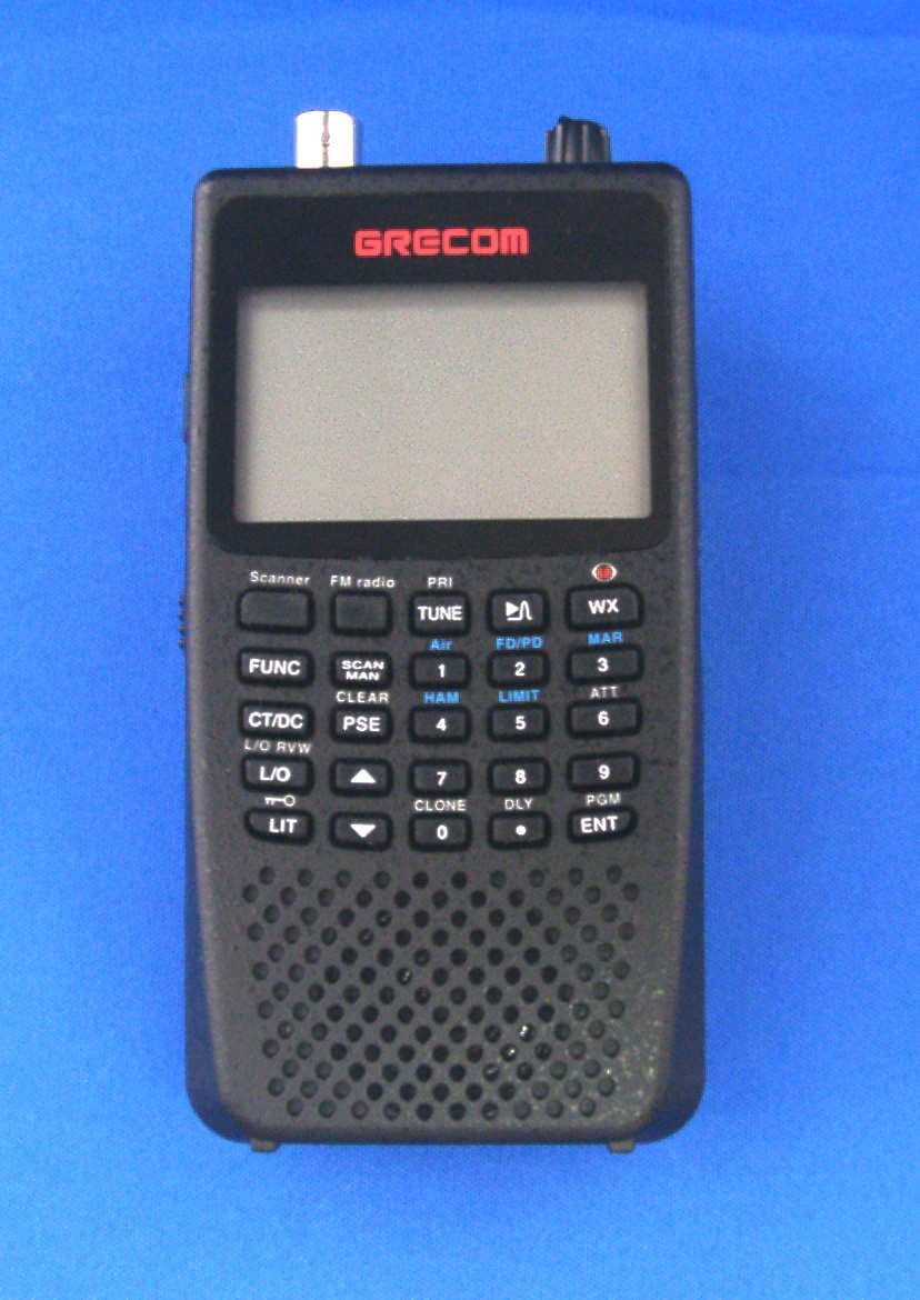
ADV0908900
Apr 03, 2012Scanning Receiver
Equipment Class
CSR - Scanning Receiver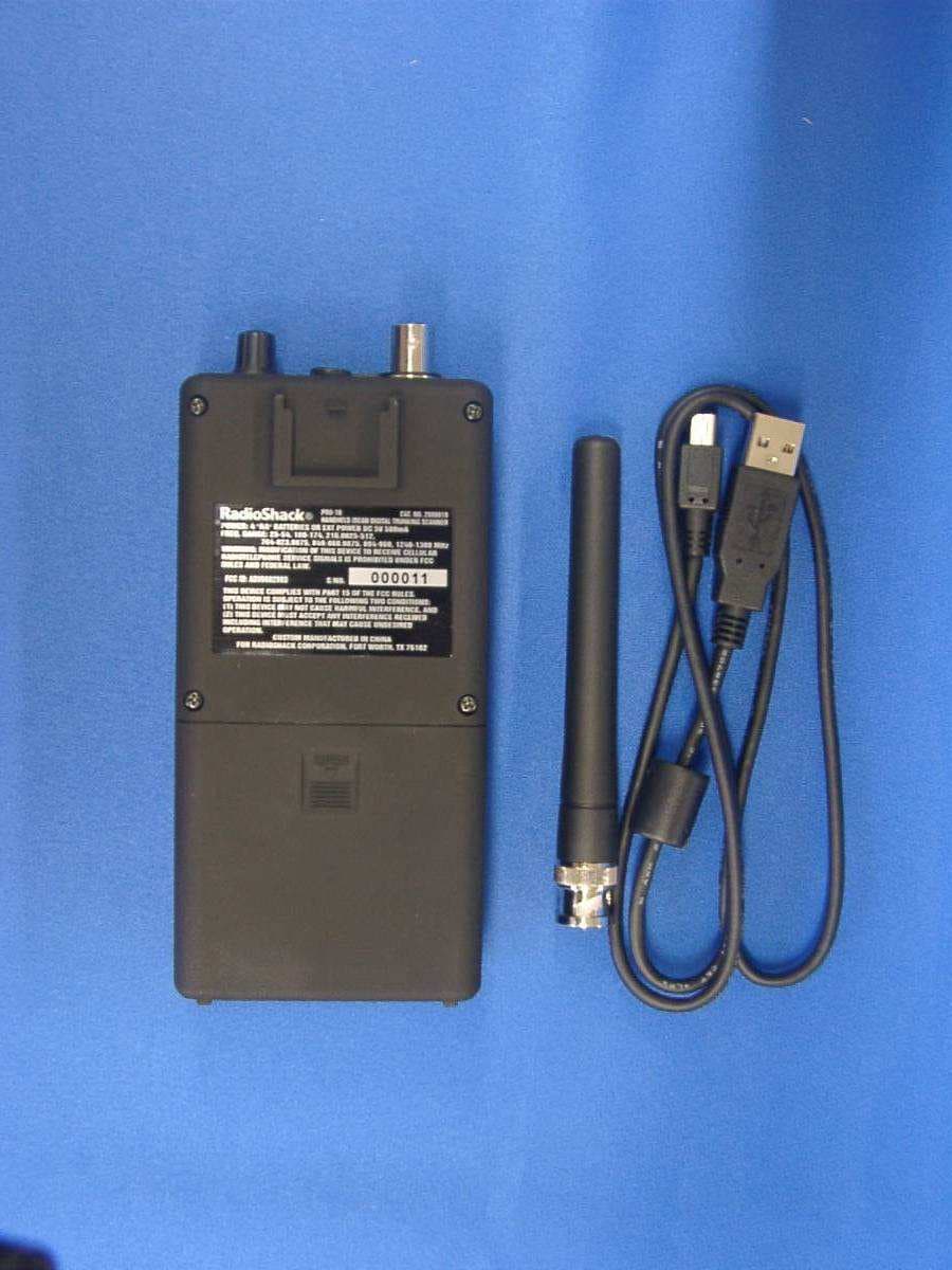
ADV0602903
Jan 27, 2011Scanning Receiver
Equipment Class
CSR - Scanning Receiver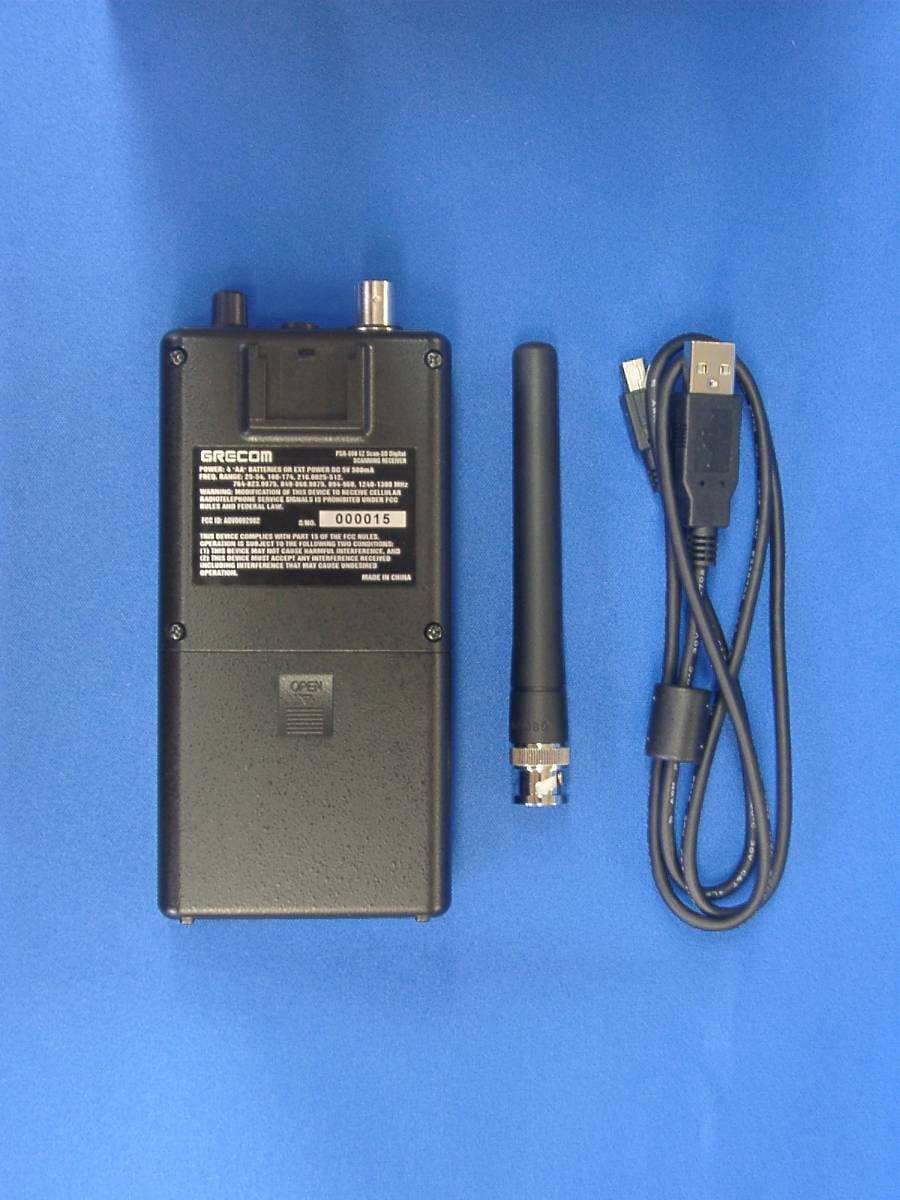
ADV0602902
Jan 27, 2011Scanning Receiver
Equipment Class
CSR - Scanning Receiver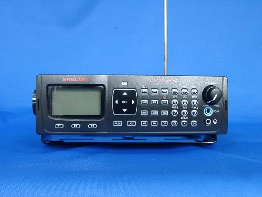
ADV0714902
Jan 16, 2011Radio Frequency Scanner
Equipment Class
CSR - Scanning Receiver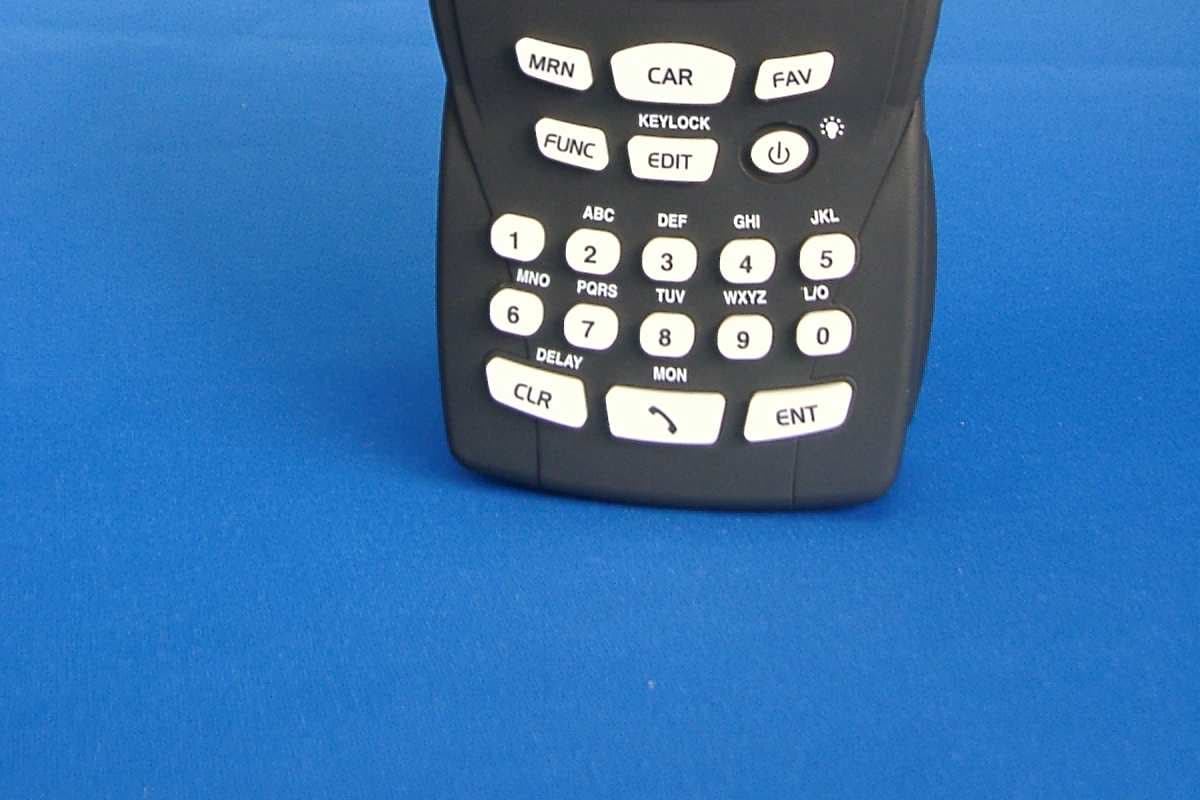
ADV0704
Jun 02, 2010Scanning Receiver
Equipment Class
CSR - Scanning Receiver