AEKA56349R49MHz RECEIVER
Taiyo Co., Ltd.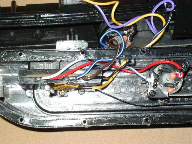
Click to zoom
Application Details
- Equipment Class
- CRR - Superregenerative Receiver
- Date of Grant
- Dec 10, 2006
- Application Purpose
- Original Equipment
- Date of Application
- Dec 10, 2006
- Equipment Note
- 49MHz RECEIVER
- Frequency Range
- 49.86000000 - 49.86000000
- Company
- Taiyo Co., Ltd.
- Country
- Japan
Documents & Files
Document Text
Text extracted from the exhibit documents filed with the FCC. Open a document above to read the original.
Users Manual
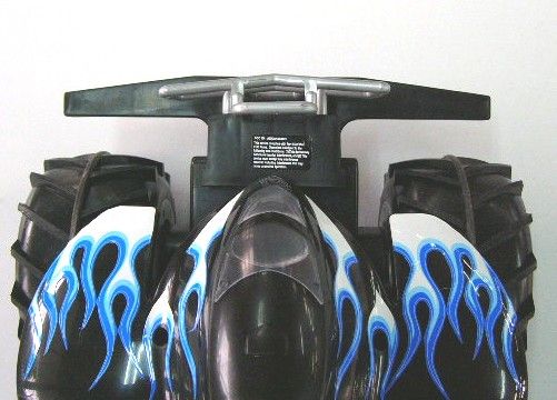
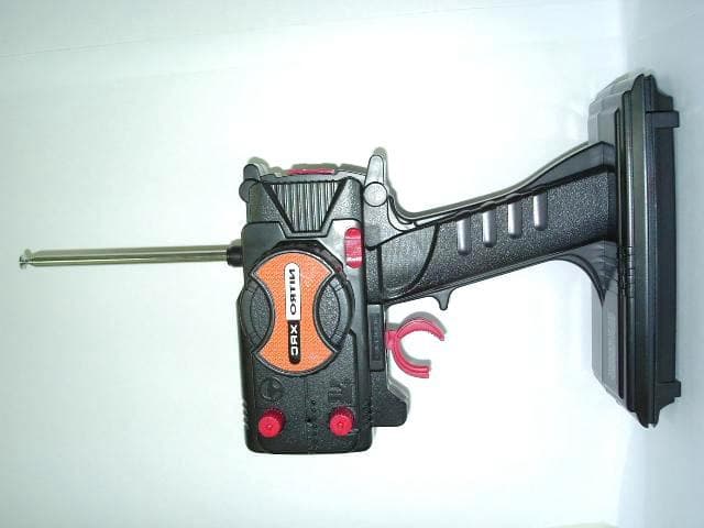
60-156 RC 1:6 Vehicle ATV Water and Land you will need... One 9V battery (not included) for the transmitter. One 6V battery pack (not included) for your vehicle. in your transmitter Turn your transmitter off. Slide open the battery cover. Insert one 9V battery, matching the polarity symbols (+ and -) marked inside. Replace when completed. in your vehicle Fully charge the 6V battery pack before use. 1. Turn your vehicle off. 2. Turn the latches to unlock and open. 3. Insert the 6V battery pack into the battery compartment with correct polarity. 4. Close and lock the battery cover. installing batteries Thank you for purchasing your RC vehicle from RadioShack. 1. Slide ON/OFF on the vehicle to ON. 2. Use the transmitter’s controls to steer your vehicle in the directions shown below. 3. Slide ON/OFF on the vehicle to OFF when you finish driving . • To go straight, push both levers upwards�downwardsupwards�downwards simultaneously. • To turn right or left, push one lever upwards and the other one downwards. • To turn clockwise or counterclockwise, push either the right lever or left lever. driving your vehicle RC 1:6 Vehicle ATV Water and Land Transmitter User’s Guide what’s included This product is warranted by RadioShack against manufacturing defects in material and workmanship under normal use for ninety (90) days from the date of purchase from RadioShack company-owned stores and authorized RadioShack franchisees and dealers. For complete warranty details and exclusions, check with your local RadioShack store. RadioShack Customer Relations 300 RadioShack Circle, Fort Worth, TX 76102 04/04 limited 90-day warranty stop forward reverse ©2006. RadioShack Corporation. All rights reserved. RadioShack and RadioShack.com are trademarks used by RadioShack Corporation. 60-156 11A06 Printed in China • Do not use batteries of different types, capacities or chemistries. • Never leave dead or weak batteries in your transmitter or vehicle. • If you do not plan to use your vehicle or transmitter for several days, remove all batteries from them. Batteries can leak chemicals that may destroy electronic parts. • If your vehicle runs slowly or does not move at all, replace or recharge the batteries. • Dispose of old batteries promptly and properly. Do not burn or bury them. • Driving your vehicle for long periods of time can generate a high heat level, which causes wear and tear on the motor. To help keep heat levels down, when your vehicle’s battery power dies, let it cool for at least 10 minutes before installing new batteries. • Do not touch the motor or batteries immediately after using the vehicle, as they may become hot during use. • If your vehicle’s motor runs, but does not respond to the transmitter, move closer to the vehicle and try again. installing batteries This equipment has been tested and found to comply with the limits for a Class B digital device, pursuant to Part 15 of the FCC Rules. These limits are designed to provide reasonable protection against harmful interference in a residential installation. This equipment generates, uses, and can radiate radio frequency energy and, if not installed and used in accordance with the instructions, may cause harmful interference to radio communications. However, there is no guarantee that interference will not occur in a particular installation. If this equipment does cause harmful interference to radio or television reception, which can be determined by turning the equipment off and on, the user is encouraged to try to correct the interference by one or more of the following measures: • Reorient or relocate the receiving antenna. • Increase the separation between the equipment and receiver. • Connect the equipment into an outlet on a circuit different from that to which the receiver is connected. Consult your local RadioShack store or an experienced radio/TV technician for help. If you cannot eliminate the interference, the FCC requires that you stop using your product. Changes or modifications not expressly approved by RadioShack may cause interference and void the user’s authority to operate the equipment. This device complies with Part 15 of the FCC Rules. Operation is subject to the following two conditions: (1) This device may not cause harmful interference, and (2) This device must accept any interference received, including interference that may cause undesired operation. This Class B digital apparatus complies with Canadian ICES-003. Cet appareil numérique de la classe B est conforme à la norme NMB-003 du Canada. RF emissions information Please read this user’s guide before installing, setting up and using your new car www.radioshack.com • This toy is recommended for children 8 years of age and older. To ensure that the child’s play is both safe and fun, please review the operating instructions and these general safety rules with the child. • Adult supervision is recommended when the vehicle is being operated. • Keep fingers, hair and loose clothing away from the wheels while the vehicle is switched ON. • To avoid accidental operation, remove the removable battery when not in use. • If the vehicle and�or transmitter get wet, stop playing. Thoroughly wipe off all moisture and allow them to air-dry completely before use. • DO NOT drive in the street! Make sure you have plenty of open space in all directions. • Regularly inspect the antenna for cracks or breaks. Do NOT bend the transmitter antenna. DO NOT use the transmitter if the antenna is broken. • The vehicle wire antenna is fragile. Never pull or tug on the antenna, as it may loosen or detach from the vehicle. Never coil or knot the antenna. • Use and store your vehicle in room temperature environments only. Handle your vehicle carefully; do not drop it. Wipe your vehicle with a damp cloth occasionally to keep it looking new. Do not drive your vehicle through puddles or mud, in the rain, snow or sand. • Modifying or tampering with the vehicle’s internal components can cause a malfunction a…
Text truncated - open the document above for the full version.
Operational Description
Circuit description for AEKA56349R Q1 is a common Base RF amplifier used as part of a super regenerative receiver. L1 and C2 comprise the tuned circuit set for 49.86 MHz. IC1 (ATS302R) contains all the demodulator and motor driver circuits. Two motors are driven by two different H pattern transistor driver circuits. Energy is supplied to the receiver and motors from 6V battery.
Parts List/Tune Up Info
NumberParts NameInsertParts NoQ'ty Parts List Date: 06/Nov/2006 Page: 1 TY-W2352-149MHzTYPE ANORMAL [PCB Name][Frequency][Type] [Buyer] No. 3723521-51 Temporary WITEM A457,A563 Function :Spec : DRAWING No. R1447 R 1RD 1/10WJ 560 TPC 1608C4111-115651 R 2RD 1/10WJ 180K TPC 1608C4111-141851 R 3,R11RD 1/10WJ 4.3K TPC 1608C4111-124352 R 4,R 6,R 8RD 1/10WJ 2.2K TPC 1608C4111-122253 R 5,R 7RD 1/10WJ 2.2M TPC 1608C4111-152252 R 9RD 1/10WJ 75K TPC 1608C4111-137551 R10RD 1/10WJ 330 TPC 1608C4111-113351 R15,R17,R19,R21RD 1/10WJ 1K TPC 1608C4111-121054 R16,R18,R20,R22RS 2W J 56 (D4x12)H4151-205624 J 1RD 1/10WJ 0 OHM (JUMPER) TPC 1608C4111-100051 J 3,J 4JUMPER WIRE D0.5x15H4151-600052 C 1CC 50VC 4pF TPC 1608C4112-1R4051 C 2CC 50VD 10pF TPC 1608C4112-101051 C 3CC 50VJ 15pF TPC 1608C4112-101551 C 4CC 50VK 272 TPC 1608C4112-122751 C 5EC 16VM 4.7uF (D4x5)H4152-354711 C 6,C 7CC 25VK 103 TPC 1608C4112-131052 C 8,C11CC 16VK 104 TPC 1608C4112-141052 C 9CC 50VJ 120pF TPC 1608C4112-111251 C10,C12CC 50VK 102 TPC 1608C4112-121052 C13CC 50VJ 33pF TPC 1608C4112-103351 C14CC 50VZ 473 TPC 1608C4112-134761 C15,C16EC 10VM 220uF (D6.3x7)H4152-372242 L 1JUMPER WIRE D0.5x5H4151-600061 L 2MINI OSC COIL 7 1/2T (5.3x5.3)H4156-307581 L 3CHOKE COIL K 3.3uHH4156-1R3311 D 1ZENER MTZ J 3.3H4155-233121 Q 1TR 2SC 2712-Y TPCC4113-201011 Q 2TR 2SA1037AK-Q or KTA1504-Y or 2SA1162-Y C4113-A00511 Q 6,Q 7,Q 8,Q 9TR 2SD1781K-Q,R or KTC3265-O,Y or 2SC3265-O,Y C4113-D00524 IC1IC ATS302R (DIP 16pin)H4157-950311 IC2,IC3IC STA491AH4157-910072 PCBP.C.B TY-W2352-14161-235221 Not on PCB Items R23RESETTABLE FUSE RUE5004151-533141 C17,C18,C19,C20CC 50VZ 104 (D5)4152-141024 L 4,L 5,L 6,L 7N.R COIL CWRL-R50M-8634174156-600074 SW 1SWITCH HM-12307-H (RED)4201-010051 M 1,M 2MOTOR3770000-002 TAIYO KOGYO CO.,LTD. Parts : RD--Carbon Resistor , RS--Fixed Carbon Resistor CC--Ceramic Capacitor , EC--Electrolytic Capacitor MC--Myler Capacitor , XC--Semiconduct Capacitor or Myler Capacitor Insert Type : C--Chip , A--Axial , R--Radial , H--Hand
Test Report
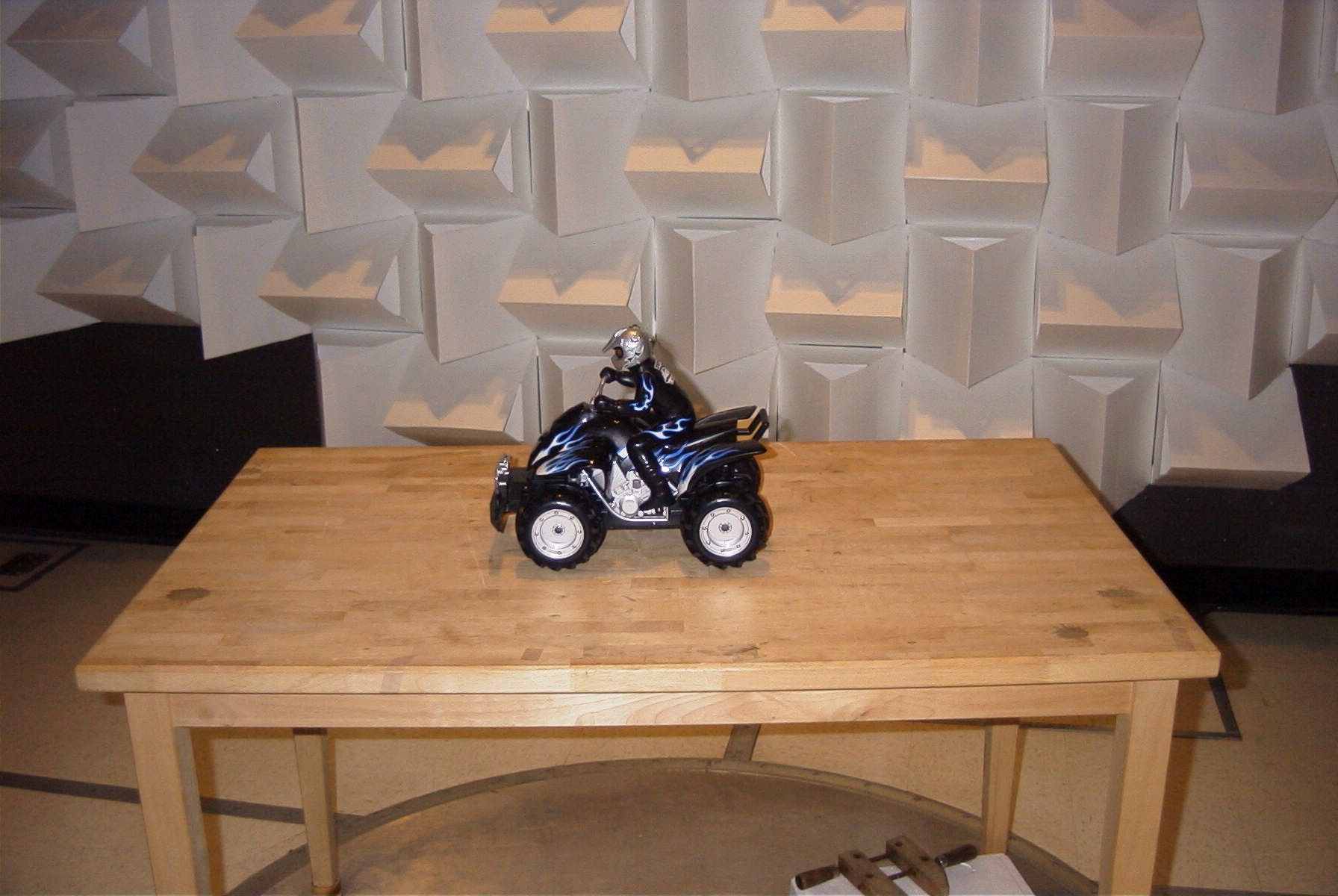
TIMCO ENGINEERING INC. 849 NW State Road 45 Newberry, Florida 32669 http://www.timcoengr.com 888.472.2424 F 352.472.2030 email: [email protected] APPLICANT: TAIYO KOGYO CO., LTD. FCC ID: AEKA56349R REPORT #: T\Taiyo_AEK\3125UT6\3125UT6TestReport.doc COVER SHEET Test Report Product Name: 49MHz RECEIVER FCC ID: AEKA56349R Applicant: TAIYO KOGYO CO., LTD. FUKOKUSEIMEI BLDG. 6F, NO. 1-2-11 KAMINARIMON, TAITO-KU TOKYO 111-0034 JAPAN Date Receipt: 11/13/2006 Date Tested: 11/17/2006 TIMCO ENGINEERING INC. 849 NW State Road 45 Newberry, Florida 32669 http://www.timcoengr.com 888.472.2424 F 352.472.2030 email: [email protected] APPLICANT: TAIYO KOGYO CO., LTD. FCC ID: AEKA56349R REPORT #: T\Taiyo_AEK\3125UT6\3125UT6TestReport.doc TABLE OF CONTENTS TABLE OF CONTENTS LIST APPLICANT: TAIYO KOGYO CO., LTD. FCC ID: AEKA56349R TEST REPORT CONTAINING: PAGE 1...............TEST EQUIPMENT LIST PAGE 2...............TEST PROCEDURES PAGE 3...............RADIATION INTERFERENCE TEST DATA EXHIBITS CONTAINING: BLOCK DIAGRAM SCHEMATIC INSTRUCTION MANUAL LABEL SAMPLE LABEL LOCATION EXTERNAL PHOTOGRAPHS INTERNAL PHOTOGRAPHS CIRCUIT DESCRIPTION TEST SET UP PHOTOGRAPH TIMCO ENGINEERING INC. 849 NW State Road 45 Newberry, Florida 32669 http://www.timcoengr.com 888.472.2424 F 352.472.2030 email: [email protected] APPLICANT: TAIYO KOGYO CO., LTD. FCC ID: AEKA56349R REPORT #: T\Taiyo_AEK\3125UT6\3125UT6TestReport.doc Page 1 of 4 EMC Equipment List Device Manufacturer Model Serial Number Cal/Char Date Due Date 3/10-Meter OATS TEI N/A N/A Listed 3/27/04 3/26/07 3-Meter OATS TEI N/A N/A Listed 1/11/06 1/10/09 Antenna: Biconnical Eaton 94455-1 1057 CAL 12/12/05 12/12/07 Antenna: Biconnical Eaton 94455-1 1096 CAL 10/11/06 10/11/08 Antenna: Biconnical Electro- Metrics BIA-25 1171 CAL 4/29/05 4/29/07 Analyzer Blue Tower Quasi-Peak Adapter HP 85650A 2811A01279 CAL 4/13/05 4/13/07 Analyzer Blue Tower RF Preselector HP 85685A 2926A00983 CAL 9/5/05 9/5/07 Analyzer Blue Tower Spectrum Analyzer HP 8568B 2928A04729 2848A18049 CAL 4/13/05 4/13/07 LISN Electro- Metrics ANS-25/2 2604 CAL 10/5/06 10/5/08 LISN Electro- Metrics EM-7820 2682 CAL 4/28/05 4/28/07 Antenna: Log- Periodic Eaton 96005 1243 CAL 12/14/05 12/14/07 TIMCO ENGINEERING INC. 849 NW State Road 45 Newberry, Florida 32669 http://www.timcoengr.com 888.472.2424 F 352.472.2030 email: [email protected] APPLICANT: TAIYO KOGYO CO., LTD. FCC ID: AEKA56349R REPORT #: T\Taiyo_AEK\3125UT6\3125UT6TestReport.doc Page 2 of 4 TEST PROCEDURE GENERAL: This report shall NOT be reproduced except in full without the written approval of TIMCO ENGINEERING, INC. RADIATION INTERFERENCE: The test procedure used was ANSI standard C63.4-2003 using a spectrum analyzer with a pre-selector. The bandwidth of the spectrum analyzer was 100 kHz with an appropriate sweep speed. The analyzer was calibrated in dB above a microvolt at the output of the antenna. The resolution bandwidth was 100kHz and the video bandwidth was 300kHz. The ambient temperature of the UUT was 80ºF with a humidity of 70%. FORMULA OF CONVERSION FACTORS: The Field Strength at 3m was established by adding the meter reading of the spectrum analyzer (which is set to read in units of dBuV) to the antenna correction factor supplied by the antenna manufacturer. The antenna correction factors are stated in terms of dB. The gain of the Pre-selector was accounted for in the Spectrum Analyzer Meter Reading. ANSI STANDARD C63.4-2003 12.1.1.1 SUPERREGENERATIVE RECEIVER: A Signal Generator was set to the unit under test operating frequency. An un- Modulated continuous wave (CW) signal was radiated at the super-regenerative receiver operating frequency to cohere the characteristic broadband emissions from the receiver. TIMCO ENGINEERING INC. 849 NW State Road 45 Newberry, Florida 32669 http://www.timcoengr.com 888.472.2424 F 352.472.2030 email: [email protected] APPLICANT: TAIYO KOGYO CO., LTD. FCC ID: AEKA56349R REPORT #: T\Taiyo_AEK\3125UT6\3125UT6TestReport.doc Page 3 of 4 APPLICANT: TAIYO KOGYO CO., LTD. FCC ID: AEKA56349R NAME OF TEST: RADIATION INTERFERENCE RULES PART NO.: 15.109 REQUIREMENTS: 30 to 88 MHz: 40.0 dBuV/M @ 3 METERS 88 to 216 MHz: 43.5 dBuV/M 216 to 960 MHz: 46.0 dBuV/M ABOVE 960 MHz: 54.0 dBuV/M TEST RESULTS: A search was made of the spectrum from 30 to 1000MHz and the measurements indicate that the unit DOES meet the FCC requirements. TEST DATA: Tuned Frequency MHz Emission Frequency MHz Meter Reading dBuV Ant. Polarity Coax Loss dB Correction Factor dB Field Strength dBuV/m Margin dB 49.9 50.90 11.3 H 0.50 11.20 23.00 17.00 49.9 50.91 15.8 V 0.50 11.23 27.53 12.47 SAMPLE CALCULATION: FSdBuV/m = MR (dBuV) + ACFdB. TEST PROCEDURE: The bandwidth of spectrum analyzer was 100 kHz with an appropriate sweep speed. When an emission was found, the table was rotated to produce the maximum signal strength. The antenna was placed in both the horizontal and vertical planes and the worse case emissions were reported. Emissions attenuated more than 20 dB below the permissible value are not reported. PERFORMED BY: RICHARD BLOCK DATE: 11/17/06 TIMCO ENGINEERING INC. 849 NW State Road 45 Newberry, Florida 32669 http://www.timcoengr.com 888.472.2424 F 352.472.2030 email: [email protected] APPLICANT: TAIYO KOGYO CO., LTD. FCC ID: AEKA56349R REPORT #: T\Taiyo_AEK\3125UT6\3125UT6TestReport.doc Page 4 of 4
Contact Information
Applicant
Hiroyuki Sasaki(Manager of Quality Assurance Section)
Test Firm
Timco Engineering, Inc.Sid Sanders
Technical Specifications
| # | Rule Parts | Frequency Range | Power Output |
|---|---|---|---|
| 1 | 15B | 49.86 MHz - 49.86 MHz | - |
Other Applications from Taiyo Co., Ltd.
AEKA54095
Oct 14, 2007REMOTE CONTROL TRANSMITTER
Equipment Class
TNB - Licensed Non-Broadcast Station Transmitter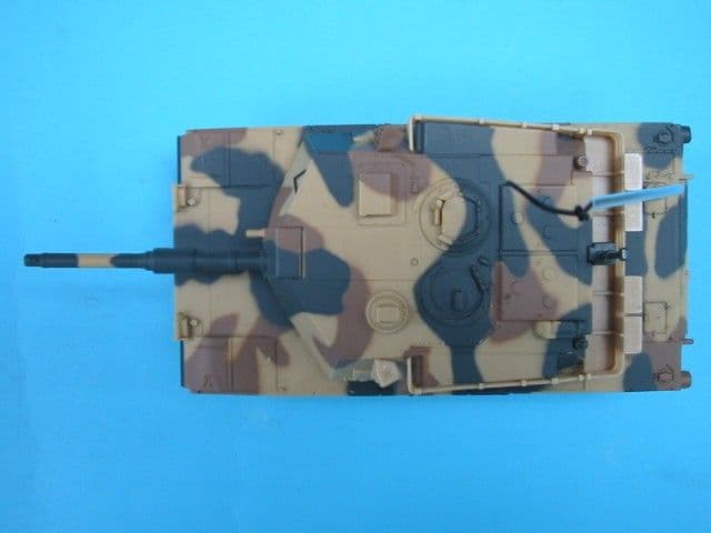
AEKA73049R
Sep 04, 2007BATTLE TANK
Equipment Class
CRR - Superregenerative Receiver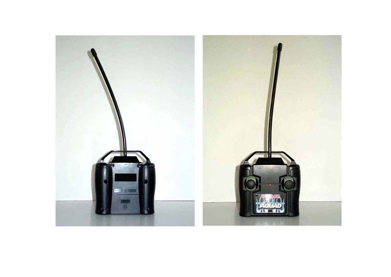
AEKA56327
Dec 06, 200627 MHz TRANSMITTER
Equipment Class
DXX - Part 15 Low Power Communication Device Transmitter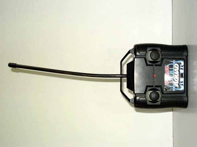
AEKA56349
Dec 06, 200649MHz TRANSMITTER
Equipment Class
DXX - Part 15 Low Power Communication Device Transmitter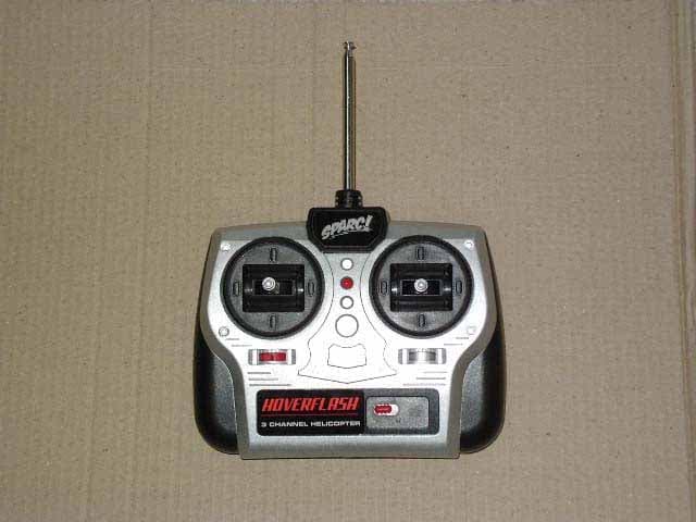
AEKA60827
Sep 26, 200627MHz REMOTE CONTROL TRANSMITTER
Equipment Class
DXX - Part 15 Low Power Communication Device Transmitter