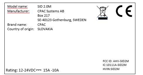
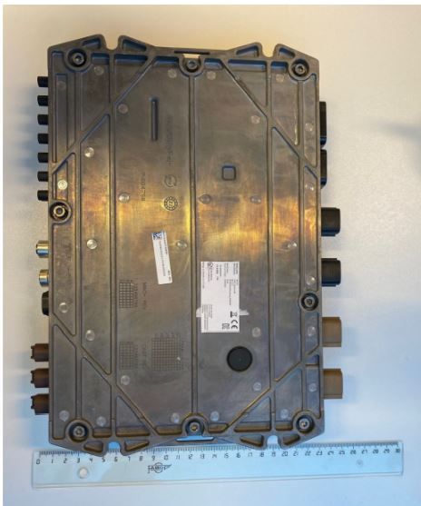
AHV-SID2MHMI Controller
CPAC Systems AB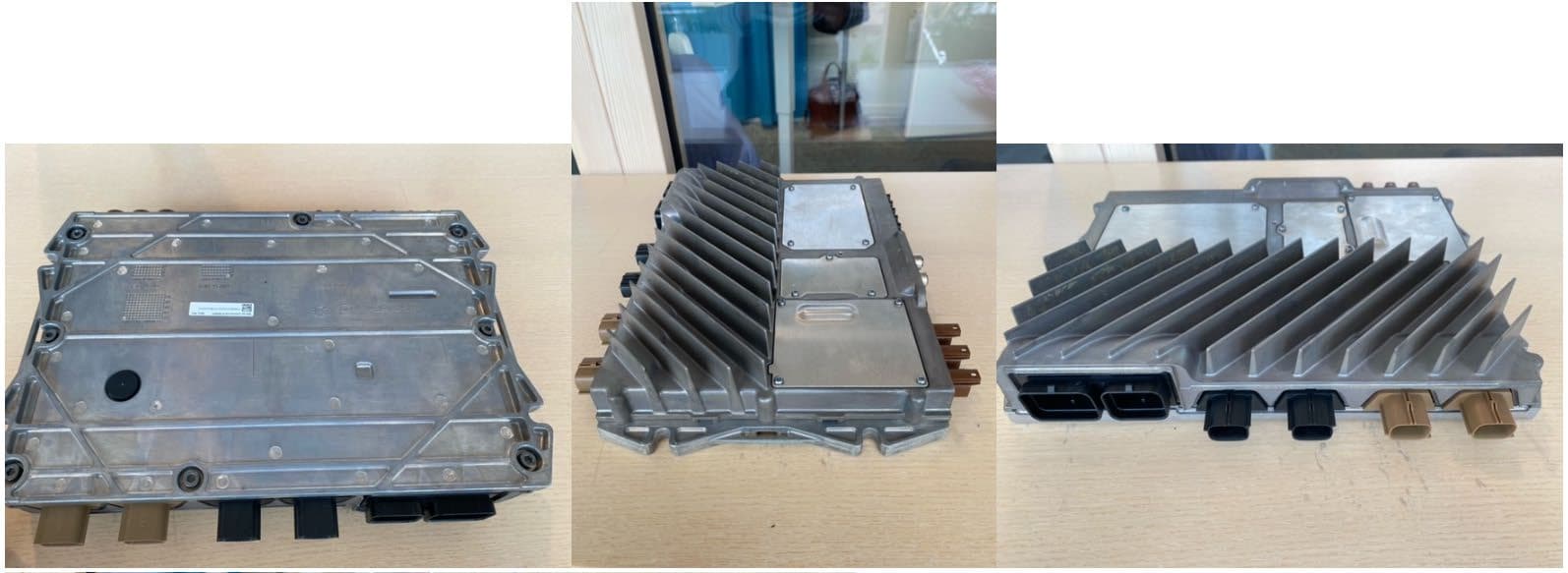
Click to zoom
Application Details
- Equipment Class
- NII - Unlicensed National Information Infrastructure TX
- Date of Grant
- Jan 04, 2024
- Application Purpose
- Original Equipment
- Date of Application
- Jan 03, 2024
- Equipment Note
- HMI Controller
- Frequency Range
- 5745.00000000 - 5825.00000000
- Company
- CPAC Systems AB
- Country
- Sweden
Documents & Files
Document Text
Text extracted from the exhibit documents filed with the FCC. Open a document above to read the original.
Users Manual
Additional Type Approval information and Safety Precautions/Warnings! Legal Statements for SID 2.0, SID 2.0M and SID 2.0MLTE. D-000849 SID_TA_Information_leaflet.docx rev: C 19w27 This document contains • Additional Type Approval information such as type approval symbols, numbers and texts for the SID 2.0 unit required by national authorities and where this information is not found on the device itself due to limited space. • Legal Statements and Safety Precautions/Warnings for the SID 2.0 unit required by national authorities. Country/ Region Additional Type Approval Information - Statements/Precautions/Warnings! Canada Contains IC: 10224A-201903EG25G This device complies with Part 15 of the FCC Rules and with RSS-210 and RSS-247 of Industry Canada. Operation is subject to the following two conditions. (1) this device may not cause harmful interference, and (2) this device must accept any interference received, including interference that may cause undesired operation. Le présent appareil est conforme aux CNR d'Industrie Canada applicables aux appareils radio exempts de licence. L'exploitation est autorisée aux deux conditions suivantes: (1) l'appareil ne doit pas produire de brouillage, et (2) l'utilisateur de l'appareil doit accepter tout brouillage radioélectrique subi, même si le brouillage est susceptible d'en compromettre le fonctionnement. NOTE: This equipment has been tested and found to comply with the limits for a Class B digital device, pursuant to Part 15 of the FCC Rules. These limits are designed to provide reasonable protection against harmful interference in a residential installation. This equipment generates, uses and can radiate radio frequency energy and, if not installed and used in accordance with the instructions, may cause harmful interference to radio communications. However, there is no guarantee that interference will not occur in a particular installation. If this equipment does cause harmful interference to radio or television reception, which can be determined by turning the equipment off and on, the user is encouraged to try to correct the interference by one or more of the following measures: · Reorient or relocate the receiving antenna. · Increase the separation between the equipment and receiver. · Connect the equipment into an outlet on a circuit different from that to which the receiver is connected. · Consult the dealer or an experienced radio/TV technician for help. USA Contains FCC ID: XMR201903EG25G This device complies with Part 15 of the FCC Rules and with RSS-210 and RSS-247 of Industry Canada. Operation is subject to the following two conditions. (1) this device may not cause harmful interference, and (2) this device must accept any interference received, including interference that may cause undesired operation. NOTE: This equipment has been tested and found to comply with the limits for a Class B digital device, pursuant to Part 15 of the FCC Rules. These limits are designed to provide reasonable protection against harmful interference in a residential installation. This equipment generates, uses and can radiate radio frequency energy and, if not installed and used in accordance with the instructions, may cause harmful interference to radio communications. However, there is no guarantee that interference will not occur in a particular installation. If this equipment does cause harmful interference to radio or television reception, which can be determined by turning the equipment off and on, the user is encouraged to try to correct the interference by one or more of the following measures: · Reorient or relocate the receiving antenna. · Increase the separation between the equipment and receiver. · Connect the equipment into an outlet on a circuit different from that to which the receiver is connected. · Consult the dealer or an experienced radio/TV technician for help. NOTICE: Changes or modifications made to this equipment not expressly approved by (manufacturer name) may void the FCC authorization to operate this equipment. Radio frequency radiation exposure Information: This equipment complies with FCC radiation exposure limits set forth for an uncontrolled environment. This equipment should be installed and operated with a minimum distance of 20 cm between the radiator and your body. This transmitter should not be co-located or operating in conjunction with any other antenna or transmitter. Additional Type Approval information and Safety Precautions/Warnings! Legal Statements for SID 2.0, SID 2.0M and SID 2.0MLTE. D-000849 SID_TA_Information_leaflet.docx rev: C 19w27 Japan Device approval numbers R: 202-JKM116 T: D23-0028 202 電波法により5.2/5.3 GHz帯は屋内使用に限ります(“5.2/5.3 GHz band is restricted to indoor use due to the Radio Law.”) LTE module: Quectel EG25-G Approval number JATE: AD 19 0040 201 / 00 Approval number TELEC: 201-190133 / 00 Europe WLAN: This device may be operated at 2412-2472 MHz, 5150-5350 MHz and 5470-5725 MHz.
Attestation Statements
CPAC SYSTEMS AB Bergskroken 3 SE-431 37 Mölndal Phone: +46 (0)31 352 16 00 Fax: +46 (0)31 352 16 99 www.cpacsystems.se Copyright by CPAC Systems AB. All rights reserved Attention: Application Examiner Re: Certification designating a U.S. agent for service of process pursuant to section 2.911(d)(7) of the FCC rules To whom it may concern, This letter is to confirm both Volvo Construction Equipment North America, LLC (“Agent”) and CPAC Systems AB (“Applicant”) acknowledge consent to obligations of each party pursuant to 47 CFR part §2.911(d)(7) of the FCC rules in regard to the agent for service of process. I, Emma Lindqvist HEREBY CERTIFY THAT I am authorized to make the representations above on behalf of the Applicant. I further acknowledge the requirement to maintain an agent extends for no less than one year after the termination of all marketing and importation or the conclusion of and commission-related proceeding involving the equipment and agree to immediately notify the FCC and Nemko Scandinavia AS if there is any change in the status identified above. Applicant Company Name: CPAC Systems AB Contact Name : Emma Lindqvist Address: Bergskroken 3, 401 26 Gothenburg, Sweden Telephone No : +467055948961 Email: [email protected] Applicant FRN: 0025650813 Signature: ____________________________________ Date: 2023/05/02___________________________________ I John Bartz, HEREBY CERTIFY THAT I am authorized to make the representations above on behalf of the Agent. I consent to the obligation to accept service of process on behalf of the applicant in regard to all certification applications to the FCC submitted by above applicant and agree to immediately notify the FCC and Nemko Scandinavia AS if there is change in this representation. Agent Company Name: Volvo Construction Equipment North America, LLC Contact Name: John Bartz Address: 304 Volvo Way, Shippensburg, PA, 17257 Telephone No: 828 674-5456 Email: [email protected] Agent FRN: 0025715467 Signature: Date: 5/3/2023
Attestation Statements
CPAC SYSTEMS AB Bergskroken 3 SE-431 37 Mölndal Phone: +46 (0)31 352 16 00 Fax: +46 (0)31 352 16 99 www.cpacsystems.se Copyright by CPAC Systems AB. All rights reserved Covered Equipment Certification Attestation Letter 9/5/2023 Nemko North America, Inc. 303 River Road Ottawa K1V 1H2 Canada ATTN.: Reviewing Engineer FCC ID: AHV-SID2M CPAC Systems AB (“the applicant”) certifies that the equipment for which authorization is sought is not “covered” equipment prohibited from receiving an equipment authorization pursuant to section 2.903 of the FCC rules. Note: If the equipment for which the applicant seeks authorization is produced by any of the entities identified on the current Covered List, the applicant should include an explanation on why the equipment is not “covered” equipment. CPAC Systems AB (“the applicant”) certifies that, as of the date of the filing of the application, the applicant is not identified on the Covered List as an entity producing “covered” equipment. Signed: Printed name: Emma Lindqvist Title: Regulatory Affairs Manager Company Name: CPAC Systems AB Date: 9/5/2023
Cover Letter(s)
CPAC SYSTEMS AB Bergskroken 3 SE-431 37 Mölndal Phone: +46 (0)31 352 16 00 Fax: +46 (0)31 352 16 99 www.cpacsystems.se Copyright by CPAC Systems AB. All rights reserved 1/9/2023 Nemko North America, Inc. 303 River Road Ottawa, Ontario, Canada K1V 1H2 AUTHORITY TO ACT AS AGENT - FCC On our behalf, I appoint Nemko North America, Inc., to act as our agent in the preparation of this application for equipment certification. I certify that submitted documents properly describe the device or system for which equipment certification is sought. I also certify that each unit manufactured, imported or marketed, as defined in FCC regulations will have affixed to it a label identical to that submitted for approval with this application. In signing this letter, Applicant certifies that neither the applicant nor any party to the application is not subject to a denial of Federal benefits, that include FCC benefits, pursuant to Section 5301 of the Anti-Drug Abuse Act of 1988, 21 U.S.C. § 862 because of a conviction for possession or distribution of a controlled substance. See 47 CFR 1.2002(b) for the definition of a "party" for these purposes. For instances where our authorized agent signs the application for certification on our behalf, I acknowledge that all responsibility for complying with the terms and conditions for certification, as specified by Nemko North America Inc., still resides still resides with us. Sincerely, Printed name: Emma Lindqvist
Cover Letter(s)
CPAC SYSTEMS AB Bergskroken 3 SE-431 37 Mölndal Phone: +46 (0)31 352 16 00 Fax: +46 (0)31 352 16 99 www.cpacsystems.se Copyright by CPAC Systems AB. All rights reserved August 23, 2023 Nemko North America, Inc. 303 River Road Ottawa, Ontario, Canada K1V 1H2 REQUEST FOR CONFIDENTIALITY - FCC FCC ID: AHV-SID2M Pursuant to Sections 0.457(d) and 0.459 of the Commission’s Rules and FCC Guidance document 726920, we hereby request permanent confidential treatment of exhibits identified as such in the table below and request they are permanently withheld from public review based on the documents containing trade secrets and proprietary information not customarily released to the public. The public disclosure of this information might be harmful to the applicant and provide unjustified benefits to its competitors. Exhibit Type of Confidentiality Requested Block Diagrams ☐ Permanent ☐ Short Term External Photos ------------------ ☐ Short Term Internal Photos ☐ Permanent* ☐ Short Term Operation Description ☐ Permanent ☐ Short Term Parts List & Placement/BOM ☒ Permanent ☐ Short Term Tune-Up Procedure ☒ Permanent ☐ Short Term Schematic Diagrams ☒ Permanent ☐ Short Term Test Setup Photos ------------------ ☐ Short Term User’s Manual ☐ Permanent* ☐ Short Term The asterisked items (*) require further information to be provided in this justification letter before permanent confidentiality will be extended to these exhibits. Please refer to FCC KDB 726920 D01 found at: https://apps.fcc.gov/oetcf/kdb/forms/FTSSearchResultPage.cfm?switch=P&id=41731 and review section II, 3) regarding specific information that must accompany these requests. Note: any documents held under the Short-Term confidentiality will automatically become public after the requested time if an appropriate extension request has not been received. Any exhibits (i.e., schematic diagrams) that may have already been requested to have “Permanent” confidentiality as shown above need not be repeated under Short-Term confidentiality request. Sincerely, Signed : Printed name: Emma Lindqvist Title: Regulatory Affairs Manager Company Name: CPAC Systems AB
Cover Letter(s)
Software Security Description – KDB 594280 D02v01r03 Section II General Description 1. Describe how any software/firmware updates for elements than can affect the device’s RF parameters will be obtained, downloaded, validated and installed. For software that is accessed through manufacturer’s website or device’s management system, describe the different levels of security as appropriate. OTA packages will be accessed by the clients play store. Program packages are encrypted by the client store, and the firmwares are encrypted by our private keys and Androids- and QUALCOMM’s security models Firmware is used as delivered from supplier and no modifications are made by development activities or the unit itself. 2. Describe the RF parameters that are modified by any software/firmware without any hardware changes. Are these parameters in some way limited such that any other software/firmware changes will not allow the device to exceed the authorized RF characteristics? We only follow the rf settings defined by the standard android open source project packages. 3. Describe in detail the authentication protocols that are in place to ensure that the source of the RF-related software/firmware is valid. Describe in detail how the RF-related software is protected against modification. The firmwares are encrypted by our private keys and Linux, Androids and qualcomms security models. 4. Describe in detail any encryption methods used to support the use of legitimate RF-related software/firmware. The firmwares are encrypted by our private keys and Linux, Androids and qualcomms security models 5. For a device that can be configured as a master and client (with active or passive scanning), explain how the device ensures compliance for each mode? In particular if the device acts as master in some band of operation and client in another; how is compliance ensured in each band of operation? Settings are configured from factory and unavailable to third party. Third-Party Access Control 1. Explain if any third parties have the capability to operate a U.S.-sold device on any other regulatory domain, frequencies, or in any manner that may allow the device to operate in violation of the device’s authorization if activated in the U.S. No RF configuration is permitted by any user. In order to change such parameters, the device needs to be connected by wire to specific after-market tool available only at authorized dealers. 2. Describe, if the device permits third-party software or firmware installation, what mechanisms are provided by the manufacturer to permit integration of such functions while ensuring that the RF parameters of the device cannot be operated outside its authorization for operation in the U.S. In the description include what controls and/or agreements are in place with providers of third-party functionality to ensure the devices’ underlying RF parameters are unchanged and how the manufacturer verifies the functionality. We do not allow third party software to modify RF parameters. 2. For Certified Transmitter modular devices, describe how the module grantee ensures that host manufacturers fully comply with these software security requirements for U-NII devices. If the module is controlled through driver software loaded in the host, describe how the drivers are controlled and managed such that the modular transmitter RF parameters are not modified outside the grant of authorization. We only follow the rf settings defined by the standard android open source project packages. Software Configuration Description – KDB 594280 D02v01r03 Section III USER CONFIGURATION GUIDE 1. Describe the user configurations permitted through the UI. If different levels of access are permitted for professional installers, system integrators or end-users, describe the differences. No RF configuration is permitted by any kind of user. a. What parameters are viewable and configurable by different parties? No RF configuration is permitted by any kind of user. b. What parameters are accessible or modifiable by the professional installer or system integrators? (1) Are the parameters in some way limited, so that the installers will not enter parameters that exceed those authorized? No RF configuration is permitted by any kind of user. (2) What controls exist that the user cannot operate the device outside its authorization in the U.S.? No RF configuration is permitted by any user. In order to change such parameters, the device needs to be connected by wire to specific after-market tool available only at authorized dealers. c. What parameters are accessible or modifiable by the end-user? (1) Are the parameters in some way limited, so that the installers will not enter parameters t exceed those authorized? No RF configuration is permitted by any kind of user. (2) What controls exist that the user cannot operate the device outside its authoriza in the U.S.? No RF configuration is permitted by any kind of user. d. Is the country code factory set? Can it be changed in the UI? (1) If it can be changed, what controls exist to ensure that the device can only operate within its authorization in the U.S.? Country code will be set at the dealer. Country code will be set using Volvo aftermarket tool and will not be accessible through the UI. e. What are the default parameters when the device is restarted? Default parameters will be as for first activation at dealer. 2. Can the radio be configured in bridge or mesh mode? If yes, an attestation may be required. Further information is available in KDB Publication 905462 D02. No. 3. For a device that can be configured as a master and client (with active or passive scanning), if this is user configurable, describe what controls exist, within the UI, to ensure compliance for each mode. If the device acts as a master in some bands and client in others, how is this configured to ensure compliance? The device cannot be master and client at the same time. 4. For a device that can be configured as di…
Text truncated - open the document above for the full version.
RF Exposure Info
FCC ID: AHV-SID2M FCC RF Exposure Compliance, Uncontrolled Environmen t, Mobile Device Evaluated according to FCC Part 2.1091Power Density is calculated from Maximum Conducted Power and Antenna Gain at prediction distance Maximum of Conducted and Radiated Output Power is u sed in the calculation. RF Function BT BLE WiFi 2.4 WiFi 5 Frequency (MHz) 2402 2402 2412 5200 Conducted Output Power (dBm) 3.00 1.00 20.00 16.00 Tune Up Tolerance (dB) 0.00 0.00 0.00 0.00 Output Power (W) 0.002 0.001 0.100 0.040 Antenna Gain (dBi) 8.00 8.00 12.00 11.00 Antenna Gain (Numeric) 6.31 6.31 15.85 12.59 Prediction Distance (cm) 20 20 20 20 Time Averaged Duty Cycle (%) 100 100 100 100 Calculated Power Density (W/m2) 0.025 0.016 3.153 0.997 Limit (W/m2) 10.00 10.00 10.00 10.00 Limits from FCC Part 1.1310(e)(1) Table 1There are no simultaneous transmissions.Antenna GainFrequency (MHz) 2402 2402 2412 5500 2J4A50PCFa, Peak Gain (dBi) 3.7 3.7 3.7 3.6 2J4A50PCFa, Peak Gain, MIMO (dBi) 6.7 7.1 Volvo Base_Ant VT Full_Feat (dBi) 8.0 8.0 8.0 7.0 Volvo WLAN Interior (dBi) 4.0 4.0 Hirschman Interior Phone PK
Test Report
Datasheet 12.12.20191-4 ANTENNA WLAN INTERIOR Pt no. 23311706 / 920 638-001 ANTENNA INTERIOR WLAN Subject to alterations • Passive transmitting and reception antennas for BT/WLAN(2.4/5 GHz) • Low body height max. 5 mm • Coverage of frequency band BT/WLAN(2.4/5 GHz) • Mounting on plastic and glass materials Technical data* ParameterTR referenceRemarksUnitsValues Dimensions / Package35x45x5 mm Housing Protection ClassREQ 22379848-6 v1 REQ 22379848-8 v1 ISO20653IK 5k2 Operating TemperatureREQ 22379848-9 v1-40- +85°C Storage Temperature-40- +85°C Cable typeREQ 22379848-41 v1Dacar 302dB/m< 0.7 @ 2.5GHz < 1.2 @ 6GHz WLAN ParameterTR referenceFrequency rangesUnitsValues Frequency bandsREQ 22379848-53 v12400 ≤ f ≤ 2485 MHz 5150 ≤ f ≤ 5925 MHz Return LossREQ 22379848-54 v12400 – 2485 MHz 5150 - 5925 MHz typ. dB≥ 8 PolarizationREQ 22379848-60 v1VP (antenna mounted vertically)linear 12.12.20192-4 Datasheet ANTENNA WLAN INTERIOR Pt no. 23311706 / 920 638-001 Technical drawings Technical data* ParameterTR referenceRemarksUnitsValues Antenna Gain (Average)REQ 22379848-55 v12400 – 2485 MHz 5150 - 5925 MHz typ. dBi≥ -1.5 ≥ 0,5 ImpedanceREQ 22379848-54 v1 Ω 50 Diagnosis ResistorREQ 22379848-67 v1kΩ51 Power HandlingREQ 22379848-48 v1dBm≥ 30 * All technical requirements are according to 22379848.06 “Antenna System P2593/P2594 Multifunctional & Single function antennas” 12.12.20193-4 Datasheet ANTENNA WLAN INTERIOR Pt no. 23311706 / 920 638-001 Antenna diagrams Gain Radiation pattern 12.12.20194-4 Datasheet ANTENNA WLAN INTERIOR Pt no. 23311706 / 920 638-001 Subject to alterations Antenna diagrams Radiation pattern 12.12.20195-4 Datasheet ANTENNA WLAN INTERIOR Pt no. 23311706 / 920 638-001 Antenna diagrams Return loss ServiceLower LimitUpper Limit WLAN 2,42400 MHz2485 MHz WLAN 55150 MHz5925 MHz Frequency Table
Test Report
REP016478 Template version: C Nemko Group Nemko Scandinavia AS, Instituttveien 6, 2007 Kjeller, Norway TEL +47 22 96 03 30 EMAIL [email protected] nemko.com/no Test Report Product Electronic Control Unit for Vehicle Integration Name and address of the applicant CPAC Systems AB Bergskroken 3 431 37 Mölndal, Sweden Name and address of the manufacturer CPAC Systems AB Bergskroken 3 431 37 Mölndal, Sweden Model SID 2.0M Rating 24V DC Trademark CPAC Systems AB Additional information WiFi, Bluetooth, LTE Tested according to FCC Part 15.407 Unlicensed National Information Infrastructure Devices (U-NII) Industry Canada RSS-247, Issue 3 Licence-Exempt Local Area Network (LE-LAN) Devices Order number PRJ0043386 Tested in period 2023-03-03 to 2023-09-14 Issue date 2023-11-22 Name and address of the testing laboratory Instituttveien 6 Kjeller, Norway www.nemko.com CAB Number FCC: NO0001 ISED: NO0470 An accredited technical test executed under the Norwegian accreditation scheme Prepared by [Frode Sveinsen] Approved by [Jan G Eriksen] This report was originally distributed electronically with digital signatures. For more information, please contact Nemko Scandinavia AS. TEST REPORT FCC Part 15.407 REP016478 FCC ID: AHV-SID2M IC: 10111A-SID2M Nemko Scandinavia AS Page 2 (123) Revision history Revision Date Comment Sign A 2023-11-22 First edition FS GENERAL REMARKS This report applies only to the sample(s) tested. It is the manufacturer's responsibility to ensure the additional production units of this product are manufactured with identical electrical and mechanical components. The manufacturer is solely responsible for any modifications to the product that could result in non-compliance with the relevant regulations. This report shall not be reproduced, except in full, without the written approval of Nemko. Any use which a third party makes of this report, or any reliance on or decisions to be made based on it, are the responsibility of such third parties. Nemko Group accepts no responsibility for damage suffered by any third party because of decisions made or actions based on this report. Opinions expressed within this report regarding general assessments and qualifications for PASS or FAIL to the standards limits and requirements, are not part of the current accreditation. Neither are opinions expressed regarding model variants covered by the testing of this report. CALIBRATION All instruments used in the tests given in this test report are calibrated and traceable to national or international standards. Between calibrations all test set-ups are controlled and verified on a regular basis by periodic checks to ensure, with 95% confidence, that the instruments remain within the calibrated levels. MEASUREMENT UNCERTAINTY Measurement uncertainties are calculated or considered for all instruments and instrument set-ups used during these tests. Uncertainty figures are found in a separate clause in this report. TEST REPORT FCC Part 15.407 REP016478 FCC ID: AHV-SID2M IC: 10111A-SID2M Nemko Scandinavia AS Page 3 (123) CONTENTS 2 INFORMATION ......................................................................................................................... 4 2.1 Test Item ................................................................................................................................................... 4 2.2 Antenna Types .......................................................................................................................................... 5 2.3 Normal test condition ................................................................................................................................. 5 2.4 Test Engineer ............................................................................................................................................ 5 2.5 Antenna Requirement ................................................................................................................................ 5 2.6 EUT Operating Modes ............................................................................................................................... 5 2.7 Comments ................................................................................................................................................. 5 2.8 EUT Power Levels ...................................................................................... Error! Bookmark not defined. 3 TEST REPORT SUMMARY ...................................................................................................... 7 3.1 General ..................................................................................................................................................... 7 3.2 Test Summary ........................................................................................................................................... 7 4 TEST RESULTS ........................................................................................................................ 8 4.1 Maximum Output Power, EIRP .................................................................................................................. 8 4.2 Emission Bandwidth ................................................................................................................................ 21 4.3 DTS Bandwidth ....................................................................................................................................... 30 4.4 Peak Power Spectral Density .................................................................................................................. 32 4.5 Unwanted Emissions ............................................................................................................................... 44 4.6 Restricted Bands of operation .................................................................................................................. 74 4.7 Radiated Emissions, 30 – 1000 MHz ............…
Text truncated - open the document above for the full version.
Test Report
TEST REPORT FCC Part 15.407 REP016478 FCC ID: AHV-SID2M IC: 10111A-SID2M Nemko Scandinavia AS Page 71 (123) Unwanted Emissions 30M-40GHz, ch046, 802.11ac HT40, MIMO, Conducted Unwanted Emissions 30M-40GHz, ch110, 802.11ac HT40, MIMO, Conducted Unwanted Emissions 30M-40GHz, ch151, 802.11ac HT40, MIMO, Conducted -60 -40 -20 0 15 30M50100M200 3005001G2G 3G5G10G2030 40G Level in dBm Frequency in Hz Spurious LimitThresholdCriticalFinal CriticalSum Level -60 -40 -20 0 15 30M50100M200 3005001G2G 3G5G10G2030 40G Level in dBm Frequency in Hz Spurious LimitThresholdCriticalFinal CriticalSum Level -60 -40 -20 0 20 30 30M50100M200 3005001G2G 3G5G10G2030 40G Level in dBm Frequency in Hz Spurious LimitThresholdCriticalFinal CriticalSum Level TEST REPORT FCC Part 15.407 REP016478 FCC ID: AHV-SID2M IC: 10111A-SID2M Nemko Scandinavia AS Page 72 (123) Unwanted Emissions 30M-40GHz, ch042, 802.11ac HT80, Ant1, Conducted Unwanted Emissions 30M-40GHz, ch106, 802.11ac HT80, Ant1, Conducted Unwanted Emissions 30M-40GHz, ch155, 802.11ac HT80, Ant1, Conducted Measured: 7152.5 MHz, Level: -34.8 dBm, Limit: -27.0 dBm, Margin: 7.8 dB -60 -40 -20 5 30M50100M200 3005001G2G 3G5G10G2030 40G Level in dBm Frequency in Hz Spurious LimitThresholdCriticalFinal CriticalSum Level -60 -40 -20 5 30M50100M200 3005001G2G 3G5G10G2030 40G Level in dBm Frequency in Hz Spurious LimitThresholdCriticalFinal CriticalSum Level -60 -40 -20 0 20 30 30M50100M200 3005001G2G 3G5G10G2030 40G Level in dBm Frequency in Hz Spurious LimitThresholdCriticalFinal Critical Sum LevelFailPass TEST REPORT FCC Part 15.407 REP016478 FCC ID: AHV-SID2M IC: 10111A-SID2M Nemko Scandinavia AS Page 73 (123) Unwanted Emissions 30M-40GHz, ch042, 802.11ac HT80, MIMO, Conducted Unwanted Emissions 30M-40GHz, ch106, 802.11ac HT80, MIMO, Conducted Unwanted Emissions 30M-40GHz, ch155, 802.11ac HT80, MIMO, Conducted -60 -40 -20 5 30M50100M200 3005001G2G 3G5G10G2030 40G Level in dBm Frequency in Hz Spurious LimitThresholdCriticalFinal CriticalSum Level -60 -40 -20 5 30M50100M200 3005001G2G 3G5G10G2030 40G Level in dBm Frequency in Hz Spurious LimitThresholdCriticalFinal CriticalSum Level -60 -40 -20 0 20 30 30M50100M200 3005001G2G 3G5G10G2030 40G Level in dBm Frequency in Hz Spurious LimitThresholdCriticalFinal CriticalSum Level TEST REPORT FCC Part 15.407 REP016478 FCC ID: AHV-SID2M IC: 10111A-SID2M Nemko Scandinavia AS Page 74 (123) 4.6 Restricted Bands of operation Restricted Bands of operation for FCC and ISED are defined in FCC Part 15.205 and ISED RSS-GEN, Issue 5 clause 8.10. Generally, no fundamentals are allowed in the restricted bands and all emissions must comply with the limits in FCC 15.209 or RSS-GEN, Issue 5, clause 8.9. FCC (MHz) ISED (MHz) FCC (GHz) ISED (GHz) 0.090-0.110 0.96-1.24 1.3-1.427 0.96-1.427 0.495-0.505 1.435-1.6265 2.1735-2.1905 1.6455-1.6465 3.020-3.026 1.660-1.710 4.125-4.128 1.7188-1.7222 4.17725-4.17775 2.2-2.3 4.20725-4.20775 2.31-2.39 5.677-5.683 2.4835-2.5 6.215-6.218 2.69-2.9 2.655-2.9 6.26775-6.26825 3.26-3.267 6.31175-6.31225 3.332-3.339 8.291-8.294 3.3458-3.358 8.362-8.366 3.6-4.4 3.5-4.4 8.37625-8.38675 4.5-5.15 8.41425-8.41475 5.35-5.46 12.29-12.293 7.25-7.75 12.51975-12.52025 8.025-8.5 12.57675-12.57725 9.0-9.2 13.36-13.41 9.3-9.5 16.42-16.423 10.6-12.7 16.69475-16.69525 13.25-13.4 16.80425-16.80475 14.47-14.5 25.5-25.67 15.35-16.2 37.5-38.25 17.7-21.4 73-74.6 22.01-23.12 74.8-75.2 23.6-24.0 108-12…
Text truncated - open the document above for the full version.
Contact Information
Applicant
Emma Karin Lindqvist(Regulatory Affairs Manager)
Test Firm
Nemko Scandinavia ASFrode Sveinsen
[email protected]+4796905548
Technical Specifications
| # | Rule Parts | Frequency Range | Power Output |
|---|---|---|---|
| 4 | 15E | 5.75 GHz - 5.83 GHz | 36.00 mW |
Other Applications from CPAC Systems AB

AHV-CTAG
Jun 25, 2024Identificatory unit that communicates with an ECU via BLE
Equipment Class
DTS - Digital Transmission System
AHV-SID2MLTE
Jan 10, 2024HMI Controller
Equipment Class
JAB - Part 15 Class B Digital Device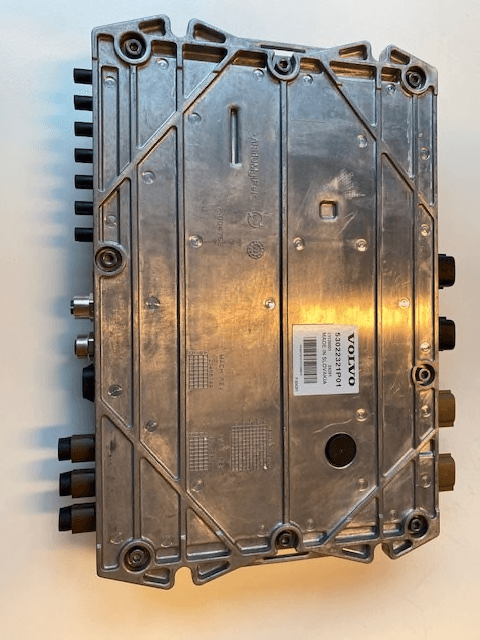
AHV-SID2B
Jan 09, 2024HMI Controller
Equipment Class
DSS - Part 15 Spread Spectrum Transmitter
AHV-ECW
Oct 03, 2023Easy Connect Wi-Fi enables remote access to vehicle data
Equipment Class
DTS - Digital Transmission System
AHV-SID2
Jul 24, 2023HMI controller
Equipment Class
DSS - Part 15 Spread Spectrum Transmitter