AIERIT10-450Voice Notification Radio Transmitter
Ritron Inc
Click to zoom
Application Details
- Equipment Class
- TNB - Licensed Non-Broadcast Station Transmitter
- Date of Grant
- Apr 06, 1999
- Application Purpose
- Original Equipment
- Date of Application
- Jan 03, 1999
- Equipment Note
- Voice Notification Radio Transmitter
- Frequency Range
- 450.00000000 - 470.00000000
- Company
- Ritron Inc
- Country
- United States
Documents & Files
Document Text
Text extracted from the exhibit documents filed with the FCC. Open a document above to read the original.
Users Manual
rtc9212b.pm5 Ritron Publication RQT-UM1 14500006 Revision B 02-12-1999 Copyright© 1999 RITRON, INC. — ALL RIGHTS RESERVED RITRON®,PATRIOT®,JOBCOM®&Quiet Call® are registered trademarks of RITRON,INC. Quick Talk TM is a trademark of RITRON, INC. P.O. Box 1998, Carmel, IN 46032-1998 • 505 W. Carmel Dr., Carmel, IN 46032 • USA PH: 317-846-1201; 1-800-USA-1-USA (1-800-872-1872) • FAX: 317-846-4978 Web: www.ritron.com • E-mail: [email protected] Quick Talk Voice Notification Radio Transmitter Basic Owner's Manual - CONSTRUCTION - FACTORIES - WAREHOUSES - FARMS - UTILITIES - AIRPORTS - STORES - SECURITY - LAW ENFORCEMENT - SHIPPING - APARTMENTS - SPORTS - HOTELS - RESTAURANTS - SCHOOLS - TRANSPORTATION rtc9212b.pm5 When using this unit, follow these basic safety instruc- tions to reduce the risk of fire, electric shock or personal injury. 1.Read and follow all instructions. 2.Disconnect the unit before cleaning. Do not use liquid or aerosol cleaners. 3.Use only approved power sources for the unit. 4.During thunderstorms, avoid contact with this unit and any external antenna system or wiring. 5.The Quick Talk switch and external power terminals are connected internally to the antenna connector. If the Quick Talk switch or power supply terminals are connected to a high voltage a hazardous condition may exist in that contact with the antenna may prove injurious or even fatal. 6.In general, the switches you connect to the Quick Talk should be independent dry contact switches and not a part of any other "live" electrical circuit 7.If you are unsure whether your installation will be safe, contact an experienced electrician or electronics technician. TABLE OF CONTENTS DESCRIPTIONPAGE WHAT THIS MANUAL COVERSii WARNINGS AND CAUTIONSii ACCESSORIES AND OPTIONSii INTRODUCTION1 General1 Model Identification1 FEATURES1 Basic Features1 Advanced Features1 CONTROLS & CONNECTORS2 PROGRAMMING3 Frequently Asked Questions3 Testing Your Programming Telephone3 Transmitter Frequency4 Quiet Call Coded Squelch Codes5 Digital Quiet Call Squelch Codes6 Testing Your Switch7 Recording Voice Messages8 Playing Back Voice Messages8 Programming Voice Phrase Repetitions9 Programming a Transmission Schedule9 Limiting the Number of Transmissions10 Resetting the unit to Factory Defaults10 INSTALLATION11 CARE AND MAINTENANCE11 Low Battery Alert Message11 Battery Replacement11 F.C.C. LICENSING12 WARRANTY12 ACCESSORIES FOR QUICK TALK These replacement and optional items are available from Ritron and its authorized dealers. ItemDescription AFB-1545Standard 19' Flexible Whip Antenna ABD-1545High Performance External Antenna RAC-02BNCoaxial Cable for External Antenna, 20 ft. RQT-UM2Advanced Features Applications Manual This manual (Ritron Item: RQT-UM1) covers basic opera- tion of the Quick Talk Voice Notification Radio Transmitter. For the majority of applications this is all you will need. There are many more complex features of the Quick Talk that are explained in the Advanced Features Manual (Ritron Item: RQT-UM2). In addition, the following application notes are available via fax by calling Ritron at 317-846-1201, or on the Ritron Website at "http://www.ritron.com". App.Note #Description of Application Bulletin RQT-AN01Using 0-5 V and 4-20 mA Analog Inputs RQT-AN02Using Terminated Alarm Loops RQT-AN03Greater Range with Optional Antennas RQT-AN03Greater Ranges using Repeaters RQT-AN04Vehicle Detectors for the Quick Talk RQT-AN05Solar Power Panels for Quick Talk RQT-AN06Ritron Custom Engineering Services RQT-AN07Interfacing to High Power Radios RQT-AN08Quick Talk Agricultural Applications RQT-AN09Quick Talk Industrial Applications RQT-AN10Quick Talk Retail Business Applications RQT-AN11Security and Alarm Applications RQT-AN12Home and Sports Application Page ii WHAT THIS MANUAL COVERS - - - - - - - WARNING - - - - - - - IMPORTANT SAFETY INFORMATION Page 1For assistance, telephone RITRON at 1-800-872-1872 or go to "http://www.ritron.com". qtm9212a.pm5 ABOUT THE QUICK TALK VOICE NOTIFICATION TRANSMITTER QUICK TALK FEATURES GENERAL INFORMATION The Quick Talk is a radio transmitter that reports changes in the status of switches by transmitting user-recorded voice messages to two-way mobile or portable radios. Quick Talk transmits your voice message when the switch change occurs and at intervals you select. Because you provide and connect the switches to your Quick Talk units, they can report changes due to intrusion, tamper, equipment malfunction, liquid level, machinery, pressure, temperature, power, smoke or leakage. The Quick Talk is easily programmed to transmit on your existing or new radio frequency and also encodes the most popular sub-audible coded squelch formats such as Quiet Call® or Digital Quiet Call TM . This enables all of your personnel with JOBCOM, PATRIOT or equivalent two-way radios to hear the voice messages instantly, and to be alerted to the current condition of each monitored location or device. Quick Talk is housed in a weather-resistant enclosure so that it can be installed in a wide variety of indoor and outdoor locations. You don't have to supply AC line power to the Quick Talk because its six internal AA Alkaline batteries will power the unit for about a year. QUICK TALK MODELS AND FREQUENCIES There are two separate Quick Talk models, one for each of the most popular professional radio communications bands. The model number appears on a label on the front of the case and a second label is placed inside the case. MODELBANDFREQUENCY RANGE RQT-150VHF-FM150 to 165 MHz RQT-450UHF-FM450 to 470 MHz Ritron manufactures mobile, portable and base station two- way radios and repeaters for use with Quick Talk, and pioneered the use of Color Dots on radios to identify frequencies. The factory-programmed, default frequencies for Quick Talk are Blue Dot (154.570 MHz) for VHF units, and Blue Star (467.925 MHz) for UHF units. The instruc- tions on page 4 describe how easy it is for the owner to change the Quick Talk transmit fr…
Text truncated - open the document above for the full version.
Attestation Statements
From:RITRON, INC. 505 West Carmel Drive Carmel, IN 46032 Date:January 5, 1999 To: Federal Communications Commission Re:Attestation for Testing and Compliance FCC ID: AIERIT10-450 This equipment has been tested in accordance with the requirements contained in the appropriate Commission regulations. To the best of my knowledge, these tests were performed using measurement procedures consistent with industry or Commission standards and demonstrate that the equipment complies with the appropriate standards. Each unit manufactured, imported or marketed as defined in the Commission’s regulations, will conform to the samples tested within the variations that can be expected due to quantity production and testing on statistical basis. I further certify that the necessary measurements were made at the facilities of Ritron, Inc. either by myself or a qualified individual under my direct supervision. Steven Paul Henke Vice President and Chief Engineer
Block Diagram
FCC ID: AIERIT10-450 RQT – 450 Transmitter Block Diagram +5V Regulator (IC302) LATCH IN CLK IN DATA IN TX MOD Synthesizer (IC301) Reference Oscillator w/Modulator (16.0125 MHz) TX Power Supply Switching and Regulation (Q312, 313, 314, 315) +V SW STROBE TX_ENABLE +V_Strobe +15V Voltage Boost (Q301) Voltage Controlled Oscillator / Buffer (Q307, 308) Modulation Balance (R310) +5VTxPA +5VTxPA +5V_TX RF Feedback Low-Pass Filter +V BATT Charge Pump (Q303 & 304) Loop Filter Control Voltage RF Final Stage (Q311) RF Driver Stage (Q309) GND +15V Ref. Modulation VCO Modulation Interface Connector to Control Board DOWN UP Pulses
Internal Photos
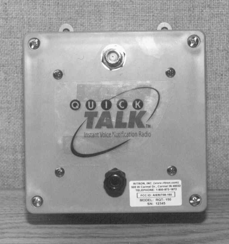
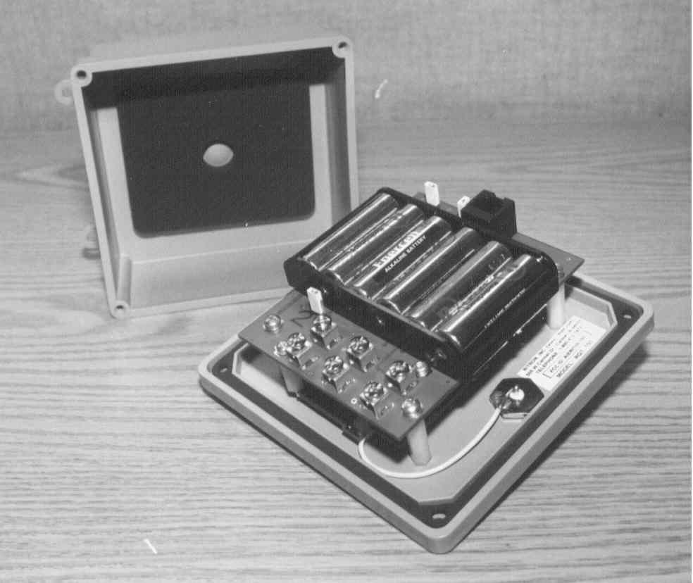
F.C.C. Equipment Authorization Application Exhibit RITRON, INC. FCC ID:AIERIT10-450Internal Photographs F.C.C. Equipment Authorization Application Exhibit RITRON, INC. FCC ID:AIERIT10-450Internal Photographs F.C.C. Equipment Authorization Application Exhibit RITRON, INC. FCC ID:AIERIT10-450Internal Photographs
Operational Description
F.C.C. Equipment Authorization Application Exhibit. RITRON, INC. FCC ID: AIERIT10-450 Page 1 of 10 Exhibit Type:Operational Description Date:January 4, 1999 This exhibit includes, but is not limited to, the following items required under FCC part 2.983 (d): (1)Type of emission. (2)Frequency range. (3)Range of operating power, and means to provide variation in operating power. (5)DC voltage chart. (6)Complete circuit diagrams. (10)A description of all frequency determining and stabilization circuits. (11)A description of the circuits used to limit spurious radiation, bandwidth and power. The Ritron model RQT-450, FCC ID: AIERIT10-450, is a 450-470 MHz, 120 milli-Watt, UHF-FM Stored Voice Notification Radio Transmitter for operation with both 25 and 12.5 KHz channel separation. It will be manufactured and marketed on a continuing basis in the United States of America by the applicant, RITRON, INC. of Carmel, Indiana. A detailed description of this device’s intended use is contained in the Owner’s Manual which is a separate exhibit. F.C.C. Equipment Authorization Application Exhibit. RITRON, INC. FCC ID: AIERIT10-450 Page 2 of 10 Technical Specifications Models:RQT-150 VHF-FM RQT-450 UHF-FM FCC ID & Rule Parts:AIERIT09-150 Parts 22, 74, 90 * AIERIT10-450 Parts 22, 74, 90, 95 * Emission Designator:11K0F3E / 16K0F3E +/- 2.5 / 5.0 KHz peak deviation Internal Jumper Selectable Operating Frequency Range:150 – 160 MHz 450 – 470 MHz Transmitter Power:120 mW Frequency Selection:Synthesized Programmable Coded Signaling Encoder:CTCSS, Quiet Call, 51 Tones DCS, Digital Quiet Call, all codes Typical Range:One half mile to a handheld radio transceiver using the standard flexible antenna. Greater range is possible if a better antenna or a radio repeater is used. Battery Life:1 year when using AA Alkaline batteries and the unit transmits a 5 second message once each hour, 24 hours per day, 5 days per week or approximately 7,000 transmissions. Internal Battery Requirement:6 AA Alkaline or NiCd batteries. External Power Requirement:9 – 15 Volts DC Jumper Enables Charging of Internal Batteries Antenna Connector:BNC, 50 Ohms Standard Antenna:Flexible Whip, 14 inches long with elbow connector. Enclosure:GE-Noryl, Grey, Ultraviolet Stable NEMA-4-4X Water-Resistant with 4 mounting ears Dimensions:5.25” x 5.25 x 2.5” Weight:1 pound, less batteries and antenna Number of Switch Inputs:2 Momentary, Latching, Analog Voltage or Resistance Switch Connectors:4 screw terminals F.C.C. Equipment Authorization Application Exhibit. RITRON, INC. FCC ID: AIERIT10-450 Page 3 of 10 External Power Input:2 screw terminals Maximum Voice Message Length:8 seconds per switch condition when 1 switch input is used. 3.25 seconds per switch condition when 2 switch inputs are used. Plus a 3.25 second location message. Auxiliary Messages:Low Battery (1.5 seconds) External Power Failure (1.5 seconds) Message Scheduling:Programmable Intervals and Repeat Times Programming Method:Programmable with a standard pulse dial telephone. Programmable Features:Transmit Frequency Sub-Audible Squelch Signaling Tones and Codes Voice Messages Message Schedules Switch Types Standard Factory Presets:Single Switch Mode Switch Closed Message Switch Open Message Low Battery Message External Power Fail Message (disabled) Messages Transmitted on switch changes Internal Battery Charging Disabled +/- 5 Khz Voice Deviation Batteries not included Frequency as marked on box NORYL is a registered trademark of GE-Plastics. * not yet Type Accepted F.C.C. Equipment Authorization Application Exhibit. RITRON, INC. FCC ID: AIERIT10-450 Page 4 of 10 RQT Theory of Operation Introduction Ritron RQT Quick Talk units are comprised of two (2) printed circuit board sub-assemblies. These are the Control and Transmitter Boards. The Control Board is common to both the RQT-150 and RQT-450 models. Below is a block diagram of the Control Board. A detailed description of the circuit blocks follows. Power Fail Detector External Power Input and Regulator Battery Input and RF Filter +5v Micropower Regulator Microcontroller Switch 1 Input Switch 2 Input EEPROM Memory SCL SDA Digital Voice Record - Playback IC w/Compressor/ Limiter A D D R R E C P L A Y L Interupt/Tone Generator +Vp Switch Programming Telephone Interface Pre- Em phasis Modulation Filter & Sum Connetors To Transmitter Board MIC MREF TX ENABLE LATCH OUT CLK OUT DATA OUT TX SUB-AUDIABLE TONES SP+ SP- INTERFACE ENABLE OFF-HOOK DET BAT.VOLT. DET F.C.C. Equipment Authorization Application Exhibit. RITRON, INC. FCC ID: AIERIT10-450 Page 5 of 10 1. DC Voltage Distribution Operating power for the radio is derived from two sources: 1.1.A. Internal Battery Pack The internal battery pack (B101) consists of six AA size alkaline or NiCd rechargeable batteries. These supply approximately 6-9 Volts to the RF interference filter (L101, L102, C109, C110) located on the control board. This power is routed through a Schottky diode to a power supply summing node at the fuse (F101). 1.1.B. External Power Supply Connections An external power supply in the range of 9-15 VDC can be connected to the screw terminals marked DC+ and DC-. These two terminals run through a RF filter (L103-L106, C101-C103) this filtered supply is then fed through a diode to a regulator transistor (Q107) and power fail circuitry (Q101). Q107 is configured as a series-pass emitter follower regulator. Zener diode CR106 and R109 supply a bias voltage (10 VDC) to the base of Q107. The emitter is filtered by C104 and fed through PJ103 and R102 to charge the battery pack when rechargeable batteries are used. PJ103 should be removed when using an external primary power source and the alkaline batteries as a backup power source. The output of Q107 is also fed to the power supply summing point at fuse (F101). This series pass regulator is needed to protect the voltage regulator IC101 from voltages above 10 VDC. The voltage at F101 (+VB) is filtered by C106 and C107 to reduce noise. The…
Text truncated - open the document above for the full version.
Parts List/Tune Up Info
F.C.C. Equipment Authorization Application Exhibit. RITRON, INC. FCC ID: AIERIT10-450 Exhibit Type: Parts List & Tune-Up Information Page 1 of 5 EXHIBIT TYPE:Tune Up Procedure DATE:November 10, 1998 Equipment Required:F.C.C. Part 68 Registered Telephone Set w/Rotary/Pulse Dialing and modular cable. Radio Frequency Communications Test Set with the following capabilities: - RF Power Meter- RF Frequency Error Meter - FM Modulation Meter- Oscilloscope Type Modulation Display Oscilloscope or high impedance Voltmeter (Do not use a low-cost “VOM”.). Procedure: Install six (6) fresh AA Alkaline batteries in the RQT-Control Board. Place jumper PJ102 in the shorted position. Set R219 the Voice Deviation Adjustment fully counter-clockwise. Connect the telephone set to the RQT’s modular jack. Connect the RQT antenna connector to the input of the RF Communications Test Set. Use this instrument per its manufacturer’s instructions to make the measurements below. Dial 978 on the telephone to restore factory default programming information. Dial 12yyyyyy to set the desired transmit frequency where yyyyyy is the transmit frequency (i.e. dialing 12154570 will set the transmit frequency to 154.570 MHz). The test frequency used for RQT-150 VHF units is 153.100 and for RQT-450 units it is 460.100 MHz. Use these frequencies to align the unit to assure proper operation across the standard frequency range. Dial 411 to activate the RQT transmitter. Measure the voltage with respect to ground on C323 and adjust the shielded variable inductor L303 on the RQT transmitter for a reading of x.xx Volts for VHF units and y.yy for UHF units. Activate the transmitter and measure the transmitter power output. This should be between 100 and 120 milli-Watts. There are no adjustments provided to change this power output. Activate the transmitter and adjust C310 on the RQT transmitter module through zero frequency error and then as close as possible to zero frequency error with respect to the programmed transmit frequency. Dial 22071 and then 411 on the telephone. The RQT transmitter will activate with a 071 code Digital Quiet Call (DQC) sub-audible coded squelch signal applied as modulation. Repeatly adjust R212 on the RQT Control Board for +/- 1000 Hz deviation and R310 on the RQT transmitter board for the best digital waveshape as viewed on the RF Test Set’s oscilloscope display. Dial 311 and then after the 3 cueing beeps, continuously whistle or speak very loudly into the telephone mouthpiece until the RQT beeps again (after about 8 seconds). Dial 411 to activate the RQT transmitter and playback what you just recorded. Adjust R219 on the RQT Control Board for +/- 5 KHz composite DQC and voice deviation. Important: For F.C.C. station licenses that require 11K0F3E modulation or systems using +/- 2.5 KHz peak transmitter deviation, remove jumper PJ102. Dial 411 and verify that the peak deviation is within this limit. Radio tune-up is complete. Enter customer specific information as described in the Owner’s Manual. < end > F.C.C. Equipment Authorization Application Exhibit. RITRON, INC. FCC ID: AIERIT10-450 Exhibit Type: Parts List & Tune-Up Information Page 2 of 5 EXHIBIT TYPE:Semiconductor Function List DATE:November 10, 1998 For the RQT Control Board assembly the following list identifies all semiconductors and their functions. Semiconductor Function List RITRON RQT Series Audio / Control Board Schematic Reference Ritron Part Manufacturer’s Designator Number Manufacturer Part Number Function CR101 04810003 Motorola 1N4001 Reverse Protection CR102 04810019 Motorola 1N5817 Reverse Protection CR103 48A1005C Motorola MMBD7000 Voltage Drop CR104 48A1005C Motorola MMBD7000 Voltage Drop CR105 04810003 Motorola 1N4001 Diode Switch, Output Isolation CR106 04820013 Motorola 1N5240 Voltage Referance CR601 48A1005C Motorola MMBD7000 External Overvoltage Shunt CR602 48A1005C Motorola MMBD7000 External Overvoltage Shunt Q101 4801001Q Motorola MMBT-5088 Power Fail Switch Q102 4801002A Motorola MMBT-3906 Telephone Enable Q103 4801002A Motorola MMBT-3906 Power Supply Switch Q104 4801001Q Motorola MMBT-5088 Telephone Enable Inverter Q105 4801002A Motorola MMBT-3906 Off Hook Switch Q106 4801001Q Motorola MMBT-5088 Off Hook Inverter Q107 48180003 Motorola BCP68T1 Series Pass Transistor IC100 31460002 Motorola MC68HC705P6CDW Microcontroller, Programmed IC101 31040002 Motorola MC78LC50NTR 5 Volt Regulator, Micropower IC102 31130002 National CD4060BCM Counter / Divider IC103 31010016 Motorola MC33202D Dual Op Amp IC104 310E0T5C N/A N/A Temperature Sensor IC105 31210001 Atmel X24C01A.SC EEPROM IC106 31180001 ISD ISD1420SI Voice Record / Playback IC107 31140001 Fairchild NC7S02M5X NOR Gate F.C.C. Equipment Authorization Application Exhibit. RITRON, INC. FCC ID: AIERIT10-450 Exhibit Type: Parts List & Tune-Up Information Page 3 of 5 EXHIBIT TYPE:Semiconductor Function List FCC PART:2.983 (d) (6) DATE:November 10, 1998 For the RQT-450 Transmitter Board assembly the following list identifies all semiconductors and their functions. Semiconductor Function List - RITRON RQT-450 Transmitter Schematic Reference Ritron Part Manufacturer’s Designator Number Manufacturer Part Number Function CR301 04810015 Motorola MV-2115 Temperature Compensation CR302 48A1005C Motorola MMBD-7000 Temperature Compensation CR303 48A1005G Motorola MMBD-352 Rectifier CR304 48B1008W Motorola MMBZ-5245B Charge Pump Voltage CR305 48C1004E Motorola MMBV-105G VCO Modulator CR307 48C1004E Motorola MMBV-105G VCO Loop Control CR310 04810001 Motorola 1N4148 Voltage Regulator Feedback Q301 4841006B Motorola MMBT-5484 Voltage Multiplier Q303 4801002A Motorola MMBT-3906 Charge Pump Q304 4801001Q Motorola MMBT-5088 Charge Pump Q307 4821007Y Motorola MMBR-941 VCO Oscillator Q308 4821007A Motorola MMBR-901 VCO Buffer Amplifier Q309 4821007A Motorola MMBR-901 Buffer Amplifier Q311 48220001 Motorola MRF-5812 RF Final Amplifier Q312 4801001Q Motorola MMBT-5088 Switched TX Voltage Control Q313 48180…
Text truncated - open the document above for the full version.
RF Exposure Info
From: RITRON, INC. 505 West Carmel Drive Carmel, IN 46032 Date: January 5, 1999 To:Federal Communications Commission Re:Statement Concerning RF Exposure FCC ID: AIERIT10-450 Per the FCC Rules and Regulations as described in the Commission’s OET Bulletin 65 this device is categorically excluded from routine RF evaluation because it is a Part 90, low power, intermittently activated transmitter. Steven Paul Henke Vice President & Chief Engineer
Test Report
F.C.C. Equipment Authorization Application Exhibit. RITRON, INC. FCC ID: AIERIT10-450 Page 1 of 28 Exhibit Type:Test Report Date:January 4, 1999 The following exhibits are contained in this file. Other exhibits required were electronically filed as separate exhibits. This file makes references to information contained in these separate exhibits. This includes but is not limited to schematics, drawings and photographs. Description of Exhibit F.C.C. Rule(s) - Statement of Certifying Engineer2.947 Manufacturer’s Statement2.983 (a) (b) (c) List of Test Equipment Used2.947 (d) Description of Measurement Facility2.948 Statement Certifying Spectrum Efficiency 90.203 (j) (3) Radio Frequency Power Output2.985 Transmitter Modulator Response2.987 (a), (b) Speech Amplifier Low Pass Filter Response2.987(a) Percent of Modulation vs. Modulation Input Voltage2.987(b) Occupied Bandwidth, Emission Masks2.989 (c), 90.210 (d), 90.211 (a) Spurious Emissions at Antenna Terminals2.991 Field Strength of Spurious Emissions2.993 (b) Frequency Stability vs. Temperature2.995 (a), 90.213 (a) (7) Frequency Stability vs. Input Voltage2.995 (d) F.C.C. Equipment Authorization Application Exhibit. RITRON, INC. FCC ID: AIERIT10-450 Page 2 of 28 EXHIBIT TYPE:Statement of Certifying Engineer FCC PART:2.947 DATE:November 10, 1998 I, Steven Paul Henke, am now and have been for the past 20 years the Vice President and Chief Engineer of RITRON, INC.. I hereby certify that all the measurements and data herein were taken by me, or under my direct supervision and that they were obtained using sound and professionally accepted engineering principles, and that they accurately reflect the performance and characteristics of the unit tested. Further I attest that manufacturing controls exist such that this data is representative of units which will be manufactured by Ritron. Signed: Steven Paul Henke Vice President and Chief Engineer F.C.C. Equipment Authorization Application Exhibit. RITRON, INC. FCC ID: AIERIT10-450 Page 3 of 28 EXHIBIT TYPE:List of Test Equipment Used to Conduct Measurements FCC PART:2.947 (d) DATE:November 10, 1998 The measurements taken for this application were obtained using one or more of the following pieces of equipment. ITEM MANUFACTURER MODEL NO.SERIAL NO. DC Power SupplyAstron VS-20M 9406023 MultimeterBeckman Industrial441050710069 MultimeterBK Precision2704A234-008455 RF Power MeterHewlett Packard435B2441A10170 RF Power Sensor*Hewlett Packard8482B2349A01936 RF Load, Calibrated*Hewlett Packard8482B2349A01936 * Traceable Calibrated Source of matching serial numbers. WattmeterTelewave448172 RF Test SetHewlett Packard 8920AR# 01498 Spectrum AnalyzerHewlett Packard8559A2010A 06979 Spectrum AnalyzerHewlett PackardHP8560E 01540 Digital Storage ScopeFluke/PhillipsPM3335DM630034 PlotterHewlett Packard7585B2503A05509 Temperature ChamberDelta Design3900 CL0-52-R PyrometerOmega 7035-J-2257504 F.C.C. Equipment Authorization Application Exhibit. RITRON, INC. FCC ID: AIERIT10-450 Page 4 of 28 EXHIBIT TYPE:Description of Measurement Facility FCC PART:2.948 DATE:November 10, 1998 The Field Strength measurements filed with this application were made on a site certified by RITRON, INC.. Data pertaining to this site is on file with the FCC and is current. This site is used on a continuing basis exclusively by RITRON, INC. and is utilized only for RF Field Strength Measurements of equipment designed and manufactured by RITRON, INC.. It is not used for measurements by or for any other party on a contract basis or otherwise. All other measurements were taken at Ritron’s Engineering Laboratory in Carmel, Indiana. F.C.C. Equipment Authorization Application Exhibit. RITRON, INC. FCC ID: AIERIT10-450 Page 5 of 28 EXHIBIT TYPE:Radio Frequency Power Output FCC PART:2.985 DATE:December 14, 1998 PROCEDURE: An RQT-450 was aligned for transmitter operation on 464.600 MHz. (Fo) per the tune-up procedure outlined in the preliminary manual. The output of a variable DC power supply was applied to the external DC power terminals of the unit. The RQT-450 antenna connector was connected to the input of the HP Power Meter. This device provides a single 50 Ohm resistively loaded input port for all measurements. The voltages across the resistor in series with the final RF power transistor were measured and Ohm’s Law was used to determine the collector current. The DC power supply voltage applied to the unit was varied from 6 to 15 Volts DC. The measured transmitter output power remained constant across this range of input voltages. This is attributable to the fact that supply voltages to the transmitter are regulated to a fixed voltage regardless of the applied power supply voltage. RQT-450, 460.100 MHz, w/ 27 Ohm Collector Resistor External RegulatedCollectorCollectorInputRF Output VoltageVoltageVoltageCurrentPowerPower Efficiency (Volts) (Volts)(Volts)(Amperes)(Watts)(Watts)(%) 6.04.93.10.0670.2070.10852% 9.04.93.10.0670.2070.10852% 12.04.93.10.0670.2070.10953% 15.04.93.10.0670.2070.10953% Certifying Engineer:Steve Henke Date:December 14,1998 F.C.C. Equipment Authorization Application Exhibit. RITRON, INC. FCC ID: AIERIT10-450 Page 6 of 28 EXHIBIT TYPE:Modulator Frequency Response FCC PART:2.987 (a), (b) DATE:November 20, 1998 PROCEDURE: The RQT-450 was aligned for transmitter operation on 464.6 MHz. (Fo) per the tune-up procedure contained in the preliminary manual. The modulation input to the transmitter was isolated by breaking the TX MOD line between the RQT Control and Transmitter boards. The HP Test Set’s Audio Generator output was connected to the Transmitter Board’s TX MOD. The frequency response of the modulator was determined to be flat within +/-1.5 from 10 Hz to 27,000 Hz. The slight variation is response is at a low frequency and is due to the two point synthesizer reference and VCO modulation method. The following pages show the results in tabular and graphical form. Certifying Engineer:Steve Henke Date:November 20, 1998 F.C.C. Equ…
Text truncated - open the document above for the full version.
Contact Information
Applicant
Sam L. Dulaney(Chief Engineer)
Technical Contact
RITRON, INC.Steven P Henke
[email protected]317-846-1201
505 West Carmel Drive · Carmel, Indiana · United States
Non-Technical Contact
RITRON, INC.Steven P Henke
[email protected]317-846-1201
Technical Specifications
| # | Rule Parts | Frequency Range | Power Output | Emission | Tolerance |
|---|---|---|---|---|---|
| 2 | 90.217(b),95A | 450 MHz - 470 MHz | 120.00 mW | 16K0F3E | 5 ppm |
Other Applications from Ritron Inc

AIERIT53-16006
Jan 04, 2023VHF Transceiver
Equipment Class
TNB - Licensed Non-Broadcast Station Transmitter
AIERIT39-26006
Aug 26, 2021VHF Modem Transceiver
Equipment Class
TNB - Licensed Non-Broadcast Station Transmitter
AIERIT51-46530
Jul 25, 2021UHF Transceiver
Equipment Class
TNB - Licensed Non-Broadcast Station Transmitter
AIERIT50-477DMR
Feb 01, 2021UHF DMR Digital / Analog 2-Way Desktop Radio
Equipment Class
TNB - Licensed Non-Broadcast Station Transmitter
AIERIT51-16006
Jan 19, 2021VHF Transceiver
Equipment Class
TNB - Licensed Non-Broadcast Station Transmitter