AIERIT13-450UHF-FM Handheld Radio Transceiver
Ritron Inc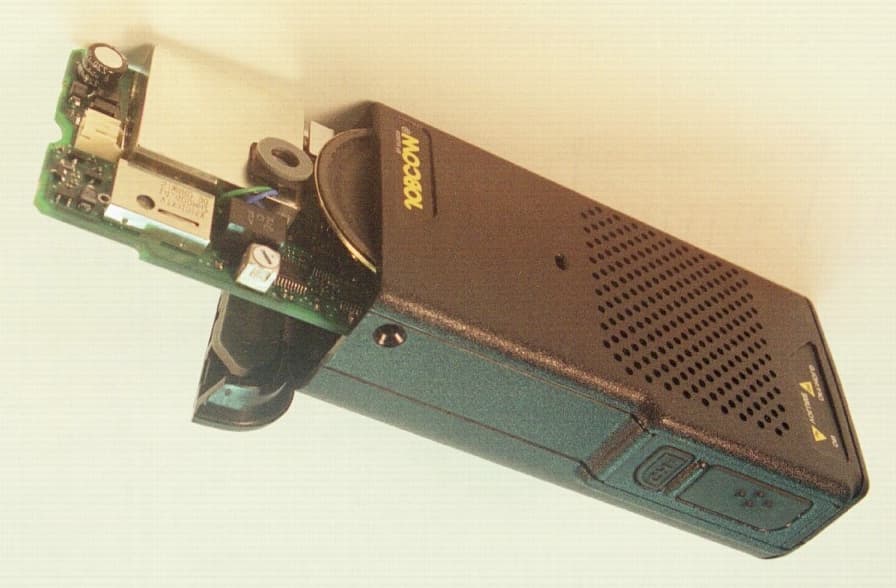
Click to zoom
Application Details
- Equipment Class
- TNF - Licensed Non-Broadcast Transmitter Held to Face
- Date of Grant
- Sep 20, 2000
- Application Purpose
- Original Equipment
- Date of Application
- Jul 06, 2000
- Equipment Note
- UHF-FM Handheld Radio Transceiver
- Frequency Range
- 450.00000000 - 470.00000000
- Company
- Ritron Inc
- Country
- United States
Documents & Files
Document Text
Text extracted from the exhibit documents filed with the FCC. Open a document above to read the original.
Users Manual
TYPE OF EXHIBIT:INSTRUCTION MANUALS FCC PART:2.1033 (c)(3) MANUFACTURER:RITRON, INC. 505 West Carmel Drive Carmel, IN 46032 MODEL:SST-444 TYPE OF UNIT:UHF-FM Handheld Transceiver FCC ID:AIERIT13-450 DATE:July 7, 2000 Included in this exhibit is a draft of the Maintenance and Operating Manual for RITRON Model Patriot SST-444 UHF-FM Handheld Transceiver. Specifically, this manual includes a technical description of the SST-444 sufficient to establish compliance with the technical standards of the applicable rule part(s). This includes, but is not limited to, the following items required under FCC Part 2.1033 (c): (2)FCC Identifier. (3)A copy of the installation and operating instructions. (4)Type of emission. (5)Frequency range. (6)Range of operating power, and means to provide variation in operating power. (7)Maximum power rating. (8)DC voltage chart. (9)Tune-up procedure. (10) A description of all frequency determining and stabilization circuits. A description of the circuits used to suppress spurious radiation, limiting modulation, and limiting power. (12) Drawing with labels for controls and complete circuit diagrams. Signed: Michael A. Pickard - Project Engineer 2 TABLE OF CONTENTS SECTIONTOPIC PAGE 1.SST-444 SPECIFICATIONS GENERAL4 RECEIVER5 TRANSMITTER6 2.INTRODUCTION GENERAL7 Inspection7 Model Identification7 FCC REGULATIONS Licensing7 Safety Standards7 3.BATTERY CARE CHARGING8 BATTERY REPLACEMENT9 PRECAUTIONS9 4.DESCRIPTION OF CONTROLS AND CONNECTORS10 Fig. 2 Controls and Connectors11 Belt Clip Installation11 5.OPERATION On-Off/Volume12 Receive12 Monitor12 Selective Signaling Squelch12 Battery Saver12 Transmit13 Channel Selection13 WHAT THE RADIO TONES MEAN Power On/Self Check “OK13 Error Tones13 Channel Select13 Tone Squelch13 Recharge Battery Alert13 OPTIONAL RADIO TONES Receiver Squelch Tone14 Busy Channel Inhibit14 Transmitter Time Out14 TROUBLESHOOTING General15 Battery15 Error Tones15 Tone Coded Squelch16 6.PROGRAMMING THE RADIO PTT (PUSH-TO-TALK) PROGRAMMING Placing the Radio in PTT Programming Mode17 How To Find Out What Is Already Programmed17 PTT Programming the Radio18 PTT Programming Mistakes18 Return To Normal Operation18 Table 1 – PTT Programming Frequency Table19 3 Table 2 – Quiet Call Codes and Frequencies19 COMPUTER SOFTWARE COPYRIGHTS19 PROGRAMMING THE RADIO USING A PC COMPUTER20 Programmable Features20 Description of Features21 7.SST-444 THEORY OF OPERATION INTRODUCTION22 POWER SUPPLY AND VOLTAGE DISTRIBUTION22 Power Strobe22 Low Battery Voltage Detection22 REFERENCE OSCILLATOR23 SYNTHESIZER 23 Pin Numbers23 Prescaler Divider / Synthesizer Controller23 VCO / Buffer Amplifiers24 Oscillator Modulation24 DIGITAL POTENTIOMETERS24 RECEIVER25 RF Amplifier25 1st Mixer25 FM Receiver Subsystem25 Voice / Tone Conditioning in Receiver Mode25 Voice Band26 Sub-Audible26 Audio Amplifier26 ANTENNA SWITCHING / LOW-PASS FILTER26 TRANSMITTER27 Keying27 +VTX Supply27 Power Amplifier27 Voice/Tone Conditioning in Transmit Mode27 Voice Band27 Sub-Audible28 MICROCONTROLLER28 8.SST-444 ALIGNMENT PROCEDURE RECOMMENDED TEST EQUIPMENT30 RADIO PREPARATION30 REFERENCE FREQUENCY31 MODULATION BALANCE31 TRANSMITTER TONE DEVIATION31 TRANSMITTER VOICE DEVIATION32 TRANSMITTER POWER32 RECEIVER SENSITIVITY AND SQUELCH32 RECEIVER NOISE SQUELCH33 SYNTHESIZER33 9.SST-444 VOLTAGE CHART Measurement Conditions34 SST-444 Voltages34 10.SST-444 SCHEMATIC REFERENCE PARTS LIST40 11.SST-444 CASE ASSEMBLY PARTS LIST47 12.SCHEMATIC AND PART PLACEMENT DRAWINGS48 4 IMPORTANT MAINTENANCE/REPAIR INFORMATION Surface Mount Repair RITRON surface mount products require special equipment and servicing techniques. Improper servicing techniques can cause permanent damage to the printed circuit boards and/or components, which is not covered by RITRON’s warranty. If you are not completely familiar with surface mounted component repair techniques, RITRON recommends that you defer maintenance to qualified service personnel. Precautions for Handling CMOS Devices This radio contains complementary metal-oxide semiconductor (CMOS) devices, which require special handling techniques. CMOS circuits are susceptible to damage by electrostatic or high voltage charges. Damage can be latent, with no failure appearing until weeks or months later. For this reason, take special precautions any time you disassemble the radio. Follow the precautions below, which are even more critical in low humidity environments. 1) Storage/transport - CMOS devices that will be stored or transported must be placed in conductive material so that all exposed leads are shorted together. CMOS devices must not be inserted into conventional plastic “snow” or plastic trays of the type that are used for other semiconductors. 2) Grounding - All CMOS devices must be placed on a grounded bench surface. The technician that will work on the radio/CMOS circuit must be grounded before handling the radio. Normally, the technician wears a conductive wrist strap in series with a 100K Ohm resistor to ground. 3) Clothing - Do not wear nylon clothing while handling CMOS circuits. 4) Power off - Remove power before connecting, removing or soldering a PC board that contains CMOS devices. 5) Power/voltage transients - Do not insert or remove CMOS devices with power applied. Check all power supplies to be used for testing CMOS devices, making sure that no voltage transients are present. 6) Soldering - Use a grounded soldering iron for soldering CMOS circuitry. 7) Lead-straightening tools - When straightening CMOS leads, provide ground straps for the tool used. PC Board Removal - Special Tool RITRON recommends using a knurled nut tool to remove the slotted knurled nuts that secure the charge and audio jacks on top of the radio. You will need two sizes of this tool, one for each jack size. Mouser Corporation is one source, stock number 382-0004 (2.5mm jack) and 382-0006 (3.5mm jack). You can reach Mouser sales and distribution center at 1-800-346-6873. Properly Attach the Synthesizer…
Text truncated - open the document above for the full version.
Attestation Statements
1 TYPE OF EXHIBIT:STATEMENT OF CERTIFYING ENGINEER FCC PART:2.947 MANUFACTURER:RITRON, INC. 505 West Carmel Drive Carmel, IN 46032 MODEL:SST-444 TYPE OF UNIT:UHF-FM Handheld Transceiver FCC ID:AIERIT13-450 DATE:July 7, 2000 I, Michael A. Pickard, have been employed by RITRON, Inc. since November 1979, working in the Engineering Department since June 1981 as a radio frequency Project Engineer. I hereby certify that all measurements and date herein were taken by me, that they were obtained using sound and accepted engineering principles, and that they accurately reflect the performance and characteristics of the units tested. Signed: Michael A. Pickard - Project Engineer 2 TYPE OF EXHIBIT:MANUFACTURER’S STATEMENT FCC PART:2.1033 (c)(1-2) MANUFACTURER:RITRON, INC. 505 West Carmel Drive Carmel, IN 46032 MODEL:SST-444 TYPE OF UNIT:UHF-FM Handheld Transceiver FCC ID:AIERIT13-450 DATE:July 7, 2000 The AIERIT13-450 is a 450 - 470 MHz UHF-FM Handheld Transceiver to be manufactured and marketed in the United States of America by the applicant, RITRON, Inc. of Carmel, Indiana. The AIERIT13-450 will be marketed by RITRON, Inc. as a Patriot model SST-444. The FCC designator for this unit is ......................... FCC ID: AIERIT13-450 RITRON, Inc. will be manufacturing and marketing the AIERIT13-450 handheld transceiver on a continuing basis. Signed: Michael A. Pickard - Project Engineer
External Photos
TYPE OF EXHIBIT:EXTERNAL PHOTOGRAPHS FCC PART:2.1033 (c)(12) MANUFACTURER:RITRON, INC. 505 West Carmel Drive Carmel, IN 46032 MODEL:SST-444 TYPE OF UNIT:UHF-FM Handheld Transceiver FCC ID:AIERIT13-450 DATE:July 7, 2000 Included in this exhibit are photographs of the RITRON Model SST-444 UHF-FM Handheld Transceiver case assembly. Additional photographs of the equipment of sufficient clarity to reveal internal construction and define component placement are included with this Certification request as a separate exhibit. Signed: Michael A. Pickard - Project Engineer
ID Label/Location Info
1 TYPE OF EXHIBIT:FCC DATA LABEL FCC PART:2.1033 (c)(11) MANUFACTURER:RITRON, INC. 505 West Carmel Drive Carmel, IN 46032 MODEL:SST-444 TYPE OF UNIT:UHF-FM Handheld Transceiver FCC ID:AIERIT13-450 DATE:July 7, 2000 The following drawing specifies the FCC Label for the SST-444. The label is placed on the SST-444 case back into a recessed area molded into the case back. A photograph is included to indicate the position of the label on the case back. Each serial number is recorded along with the date of manufacture and is kept on file at RITRON, Inc. The FCC data label will be made of a “tamper proof” destructive, .002” thick silver mylar material laminated to .003” Lexan film with Hi-Tack adhesive backing. The label background will be black with all graphics in silver. The area containing the FCC ID designator will be silver with black graphics. A 2nd small label of the same material will contain the manufacture date. Serialization will begin with the serial number A1234. The combined size of the serial label and manufacturing date label is 2.979” x 0.980”. Signed: Michael A. Pickard - Project Engineer 2 TOLERANCES(EXCEPT AS NOTED) DECIMAL FRACTIONAL ANGULAR REVISIONS NO. DATE BY 1 2 34 5 DRAWN BYCHK'DTRACED SCALEDATEAPP'D MATERIALDRAWING NO. RITRON, INC. 505 West Carmel Drive Carmel, IN 46032 2 : 1 6/20/00 MAP SST-444 FCC / MODEL LABEL 14200094 L C 1.95" .980" 5.525" 2.760" 2.745" 1.38" L C FRONT VIEW (scale 2:1) VIEW A - ART WORK REGISTRATION (scale 1:1) YY X X SIDE VIEW (scale 2:1) GRAPHICS TO BE SUB-SURFACE, PRINTED ON MATTE SIDE FCC ID: AIERIT13-450 FREQ: 450-470 MADE IN THE U.S.A. BY RITRON, INC. PH: 317-846-1201 MODEL: SST-444 SN: AREA FOR SERIAL NUMBER VELVET SIDE MATTE SIDE (+.000 -.020) (+.000 -.020) .062 R 2 PLC X X YY "FCC ID: AIERIT13-450" AND "FREQ: 450-470" Black characters, bold helvetica type style (font), 5 point type size, aligned left in silver box. Allow space between box border and text as shown. "FOR BEST PERFORMANCE . . OF SERVICE" S ilver characters, helvetica type style, 5 point type size, centered horizontally in the right half of the label as shown. "OPERATING INSTRUCTIONS . . . HOLD FOR OFF" S ilver characters, bold helvetica type style, 3 point type size, aligned left in the box. Allow space between box border and text as shown. "MADE IN THE USA BY RITRON, INC." and PHONE/MODEL numbers are silver characters, bold helvetica type style, 5 point type size. Align left as shown. "SN" is silver characters, bold helvetica type style, 5 point type size. A lign as shown . TYPE SPECIFICATIONS: 1. 2.3. 4. 5. MATERIAL - .010 thick clear lexan film (#8B 35) with velvet/matte finish. ADHESIVE - Part to have .002 thick "tamper proof" destructive adhesive ( Scotch #467 or Engineering approved equivalent) with an easy to remove liner. GRAPHICS - To be subsurface printed on the matte side. To be per Ritron art work definition (see type specifications at left). To be registered to the part edge as shown in View A . The area designated for the SERIAL NUMBER will be silver, and is 0.55" x 0.14". Serial number characters are black, 8 point type size. Serial number to be centered within the silver area. NUMBER SERIALIZATION to use hot stamp process on .0015" silver compucal material with bold black print. PATRIOT SST Logo provided on stat sheet. Logo dimensions are 0.805" x 0.23", represented in View A by the box outline. (B ox is for sizing only and will not appear.) Logo is silver. Center the logo horizontally, in the left half of the label as sh own. NOTES: 1.2. 3.4.5. A 1234 .062 R 2 PLC FOR BEST PERFORMANCE REPLACE BATERY PACK AFTER A MAXIMUM OF 18 MONTHS OF SERVICE. OPERATING INSTRUCTIONS - PRESS FOR ON . . . HOLD FOR VOLUME UP PRESS FOR VOLUME DOWN . . . HOLD FOR OFF FOR BEST PERFORMANCE REPLACE BATERY PACK AFTER A MAXIMUM OF 18 MONTHS OF SERVICE. MADE IN THE U.S.A. BY RITRON, INC. PH: 317-846-1201 MODEL: SST-444 SN: PATRIOT SST LOGO HERE FCC ID: AIERIT13-450 FREQ: 450-470OPERATING INSTRUCTIONS - PRESS FOR ON . . . HOLD FOR VOLUME UP PRESS FOR VOLUME DOWN . . . HOLD FOR OFF PATRIOT SST LOGO HERE 6. www.ritron.com .050 BORDER ALL AROUND (+/- .010) A 1234 www.ritron.com 3 TOLERANCES(EXCEPT AS NOTED) DECIMAL FRACTIONAL ANGULAR REVISIONS NO. DATE BY 1 2 34 5 DRAWN BYCHK'DTRACED SCALEDATEAPP'D MATERIALDRAWING NO. RITRON, INC. 505 West Carmel Drive Carmel, IN 46032 2 : 1 06/21/95 DHD SST/JMX FCC LABEL - MFG DATE 14200037 "MFG DATE" will be silver characters, bold helvetica type style, 5 point type size. Align left as shown. TYPE SPECIFICATIONS: MATERIAL - .002 thick silver mylar, laminated to .003 thick Lexan film (#8B35) with velvet/matte finish. ADHESIVE - Part to have .002 thick adhesive (Scotch #9471 or engineering approved equivalent) with an easy to remove liner. GRAPHICS - To be per Ritron art work definition. To be registered to the part edge as shown in view A. Background color to be black. The area designated for the date will be silver, and is 0.385" X 0.13". Characters will be 8 point type size. Date to be centered within the silver area. Date to use hot stamp process on .002" silver mylar material with bold black print. NOTES: 1. 2.3.4.5. FRONT VIEW (scale 2:1) YY X AREA FOR DATE .062 R 2 PLC X 1.95" .980" (+.000 -.020) 0.4" .200" (+/-.010) 06/95 MFG DATE: VIEW A - ART WORK REGISTRATION (scale 1:1) .050 (+/- .010) .020 (+/- .010) MFG DATE: 06/95 .050 (+/- .010)
Internal Photos
TYPE OF EXHIBIT:INTERNAL PHOTOGRAPHS FCC PART:2.1033 (c)(12) MANUFACTURER:RITRON, INC. 505 West Carmel Drive Carmel, IN 46032 MODEL:SST-444 TYPE OF UNIT:UHF-FM Handheld Transceiver FCC ID:AIERIT13-450 DATE:July 7, 2000 Included in this exhibit are photographs of the RITRON Model SST-444 UHF-FM Handheld Transceiver printed circuit board assembly. Additional photographs of the equipment of sufficient clarity to reveal equipment construction and layout, labels for controls and meters, and chassis assembly are included with this Certification request as separate exhibits. Signed: Michael A. Pickard - Project Engineer
Operational Description
TYPE OF EXHIBIT:OPERATIONAL DESCRIPTION FCC PART:2.1033 (c)(3) MANUFACTURER:RITRON, INC. 505 West Carmel Drive Carmel, IN 46032 MODEL:SST-444 TYPE OF UNIT:UHF-FM Handheld Transceiver FCC ID:AIERIT13-450 DATE:July 7, 2000 Included in this exhibit is the operating instructions and theory of operation for the SST-444. The operating instructions and theory of operation included in this exhibit are excepts of the Maintenance and Operating Manual for RITRON Model Patriot SST-444 UHF-FM Handheld Transceiver. The complete Maintenance and Operating Manual is included with this application for Certification as a separate exhibit. Signed: Michael A. Pickard - Project Engineer 2 DESCRIPTION OF CONTROLS AND CONNECTORS Antenna The flexible antenna radiates and receives radio signals. Before using the radio, be sure the antenna base is threaded fully into the radio’s antenna bushing. VHF and UHF antennas are not interchangeable. Use only the antenna type packaged with the radio. A VHF antenna is pictured in FIG-2. (The UHF antenna is smaller in diameter.) On/Volume Up This button switches on the radio, then increases the volume if you continue to press. Off/Volume Down This button decreases the volume, then shuts off the radio if you continue to press. Channel Select Pressing this button selects the next channel. When the maximum number of channels is reached and you press this button, the radio resets to channel 1. Speaker The speaker allows you to hear calls on your channel. Push-To-Talk Button The PTT activates the transmitter, and must be held down while you talk into the microphone. Release the PTT button to receive. Microphone The microphone converts your voice into electrical impulses, which are carried with your broadcast to receiving radios. Hold the radio about two inches away and talk into the microphone while transmitting. Shouting does not improve the listener’s reception. Audio Accessory Jack This jack connects speaker audio to optional accessories, such as a remote speaker/microphone or an earphone. For accessories that have a two-plug connector, the smaller plug is inserted into the charge jack. This jack is also used to program the radio using the optional PC programming kit. Charge Jack The battery may be charged through this jack using a standard RITRON wall socket charger cube. This jack also connects microphone audio to the optional remote speaker/microphone. Battery Access (Case Bottom) The battery door on the case bottom may be removed to access the battery. (Refer to the battery section of this manual.) Drop-in Charger Contacts Two charger contacts in the bottom of the SST-444 radio case allow the battery pack to be charged using an optional RITRON drop-in charger (model BCPS-FS). Jack Cover This rubber cover seals out dust and moisture, etc. Snap the cover into the audio accessory and charge jack openings when the jacks are not being used. 3 DESCRIPTION OF CONTROLS AND CONNECTORS CH ON OFF/HOLD VOLUME Belt Clip Installation If you are going to attach the belt clip to the handheld, follow these instructions: 1) The belt clip is fastened to the radio case back with the Philips head screw provided. Use the screw included, since a longer screw might damage the radio’s electronics. Do not use petroleum solvents of any kind on the radio. These can corrode the case. 2) Place the belt clip on top of the radio case back, with the screw hole in the aligned with the hole in the radio case. 3) Using the screw that came with this accessory, attach the clip to the radio. Antenna Vol Down/Off On/Vol Up Audio Accessory Jack Jack Cover Charge Jack Speaker Microphone Push-to-Talk Channel Selector Battery Access Door (Case bottom) Battery Charger Contacts (Case bottom) Fig. 2 Controls and Accessory Connectors 4 OPERATION On-off/Volume To switch on the radio - press the on/volume up button. To adjust the volume - press the volume up button until you reach the desired level. You should hear noise and any broadcasts on the channel. To turn off the radio - press and hold the off/volume down button until two tones sound. To determine whether the radio is on - press the volume down button. If the radio is on, noise or activity on the channel is heard. Receive To hear calls from other users - adjust the volume as desired. The radio can receive broadcasts while the Push-To-Talk button is not being pressed. Whether or not you hear these broadcasts depends upon the squelch settings. There are two types of squelch used in the SST-444 portable. First is carrier squelch. This lets you hear all broadcasts on your channel strong enough for the radio to detect, and silences noise. Second is one of the selective signaling or “tone squelch” formats available on the SST-444. This allows you to screen out “on-channel” broadcasts that do not carry the correct code programmed for the radio. Note: It is possible that the beginning of a call might be missed while the radio is in battery saver mode. If this happens, ask the caller to repeat his message. Monitor To monitor the channel - press one of the volume control buttons. When you press the volume up or the volume down button, squelch turns off and all radio traffic on the channel (and noise) sounds in the speaker. Selective Signaling Squelch To activate tone squelch - simultaneously press both of the volume buttons. Hold for a second or two before releasing. When tone squelch is turned on, the handheld sounds one beep. When carrier squelch is on, the radio emits a "double beep." Note: If you continue to hold down the volume buttons after the beep (or double beep), the radio will start beeping repeatedly. This means that squelch is turned off. Release the buttons. To restore squelch, press and hold both of the volume buttons until the radio sounds a beep or double beep. Battery Saver The handheld has a programmable "battery saver" feature that conserves battery power. The battery saver constantly checks the radio's transmitter, receiver and controls for activity. If …
Text truncated - open the document above for the full version.
Parts List/Tune Up Info
TYPE OF EXHIBIT:TUNE-UP PROCEDURE AND PARTS LIST FCC PART:2.1033 (c)(9) MANUFACTURER:RITRON, INC. 505 West Carmel Drive Carmel, IN 46032 MODEL:SST-444 TYPE OF UNIT:UHF-FM Handheld Transceiver FCC ID:AIERIT13-450 DATE:July 7, 2000 Included in this exhibit is the tune-up procedure, parts list and semiconductor function list for the SST-444. The tune-up procedure and parts list included in this exhibit are excepts of the Maintenance and Operating Manual for RITRON Model Patriot SST-444 UHF-FM Handheld Transceiver. The complete Maintenance and Operating Manual is included with this application for Certification as a separate exhibit. Signed: Michael A. Pickard - Project Engineer 2 SST-444 ALIGNMENT PROCEDURE An authorized RF service technician must perform test and alignment of the SST-444. Do not attempt service of the SST-444 if not completely familiar with the operation of frequency synthesized radio operation. The SST-444 can operate in either Narrow Band (2.5 KHz deviation) or Wide Band (5 KHz deviation) systems. RECOMMENDED TEST EQUIPMENT 1) 0 to +15 VDC, 2A current-limited power supply3) Oscilloscope (to 20 MHz) 2) RF Communications Test Set (to 470 MHz) with:4) VTVM or DMM - FM Deviation Meter - RF Wattmeter5) RITRON PC Programming Kit - Frequency Counter (to 470 MHz) - SINAD Measuring Device6) RITRON SST-SRVBD Test Module RADIO PREPARATION 1) Make sure the radio battery is fully charged. 2) Install the RITRON SST-SRVBD test assembly and serial programming cable as follows: a) Remove the SST-444 antenna from the radio. b) Plug the SST-SRVBD into the 2.5 mm and 3.5 mm jacks on top of the radio. c) Screw the SST-SRVBD antenna nut fully into the SST-444 antenna connector. d) Set the jumper on the SST-SRVBD assembly to the “UHF” position. e) Connect the serial programming cable from the PC computer (with the RITRON PC programming kit software installed) to the SST-SRVBD test assembly 3) Connect the FM communications test set to the BNC connector on the SST-SRVBD test assembly. 4) Turn on the radio to place it in operating mode. 5) From the PC Programmer on-screen menu, select “Tune Radio” to display the Alignment screen. 6) Set the RF Communications Test set to the Alignment Frequency indicated on the Alignment screen. 7) Press the appropriate “Select” button on the Alignment screen to make the following adjustments: SELECTAlignment FrequencyTransmit frequency Mod BalModulation balance ToneQC/DQC tone encode deviation – wide band QC/DQC tone encode deviation – narrow band VoiceVoice deviation with no tone – wide band Voice deviation with no tone – narrow band Voice deviation with tone – wide band Voice deviation with tone – narrow band PowerLow transmitter power High transmitter power 8) After you have completed alignment of the SST-444, turn the radio off. This will remove the test frequencies and return to operation on the customer’s programmed frequencies. 3 SST-444 ALIGNMENT PROCEDURE REFERENCE FREQUENCY 1) Make sure that the unit has been switched on and is at room temperature (approximately +25° C) 2) Select “Frequency” from the PC Programmer “Alignment” screen. 3) Set the RF communications test set to the Alignment Frequency on the Alignment screen. 4) Press the “Tune” button on the Alignment screen to activate the transmitter. 5) Transmitter frequency error should be less than +/- 500 Hz. 6) If frequency adjustment is required, press the left arrow on the tuning bar to lower the frequency or the right arrow to raise the frequency. 7) Press the “Save” button to store the new alignment setting or “Cancel” to leave setting unchanged. MODULATION BALANCE Transmitter modulation balance has been set at the factory and should not require adjustment. 1) Select “Mod Bal” from the PC Programmer “Alignment” screen. 2) Set the RF communications test set to the Alignment Frequency on the Alignment screen. 3) Press the “Tune” button on the Alignment screen to activate the transmitter. 4) Check the de-modulated waveform for a 20 Hz square wave. 5) If adjustment of the modulation balance is required, press the left arrow on the tuning bar to flatten the top of the waveform or the right arrow to reduce overshoot. 6) Press the “Save” button to store the new alignment setting or “Cancel” to leave setting unchanged. TRANSMITTER TONE DEVIATION Transmitter tone deviation has been set at the factory and should not require adjustment. 1) Select “Tone” from the PC Programmer “Alignment” screen. 2) Set the RF communications test set to the transmit frequency on the screen. 3) Select either “Wide Band” or “Narrow Band” by pressing the desired option button. 4) Press the “Tune” button on the Alignment screen to activate the transmitter. 5) If adjustment of the tone deviation is required, press the left arrow on the tuning bar to lower deviation or the right arrow to raise deviation. 6) Press the “Save” button to store the new alignment setting or “Cancel” to leave setting unchanged. 4 SST-444 ALIGNMENT PROCEDURE TRANSMITTER VOICE DEVIATION Transmitter voice deviation has been set at the factory and should not require adjustment. 1) Select “Voice” from the PC Programmer “Alignment” screen. 2) Set the RF communications test set to the transmit frequency on the screen. 3) Select “Voice Only - Wide Band“, “Voice Only - Narrow Band”, “Voice & Tone – Wide Band”, or “Voice & Tone – Narrow Band” by pressing the desired option button. 4) Press the “Tune” button on the Alignment screen to activate the transmitter. 5) If adjustment of the voice deviation is required, press the left arrow on the tuning bar to lower deviation or the right arrow to raise deviation. 6) Press the “Save” button to store the new alignment setting or “Cancel” to leave setting unchanged. TRANSMITTER POWER Transmitter power has been set at the factory and should not require adjustment. 1) Select “Power” from the PC Programmer “Alignment” screen. 2) Set the RF communications test set to the transmit frequency on the screen. 3) Select “Low Power” …
Text truncated - open the document above for the full version.
RF Exposure Info
-----Original Message----- From:OET [mailto:[email protected]] Sent:Friday, July 28, 2000 8:02 AM To:[email protected] Subject: To:Sam Dulaney, null From:Frank Coperich [email protected] FCC Application Processing Branch Re:FCC ID AIERIT13-450 Applicant: Ritron I nc Correspondence Reference Number:15304 731 Confirmation Number:EA98126 Date of Original E-Mail:07/28/2000 1.) Because this unit is used with a specific antenna provided with the unit, the tests for power output should be performed as radiated to determine ERP via the substitution method. Requested data follows. 2.) Likewise, the tests for radiated spurious emissions should be performed with the unit operating with it’s normal antenna connected. Requested data follows. 3.) Although hand-held, push-to-talk device are categorically excluded rom routine RF exposure evaluation for demonstrating SAR compliance, they are not exempted from compliance. Because of the high measured output for this device, additional information is needed to determine if SAR compliance can be assured or if a request for RF exposure evaluation under the provisions of 1.1307(d) would be necessary. Please provide the following information, if applicable, so that we can consult with headquarters to determine if a request for SAR evaluation is necessary - (a) the type and number of antenna(s) to be used for this device and a detailed description of the antenna connector, if any. Two antennas are available for this device; an AFS-450 and an AFS-450-S. Both attach to the top of the device and are shortened quarterwave whips. The connector is a ¼-20 stud attached to the antenna. It would be difficult to connect any other connector or antenna other than that supplied by the manufacturer. (b) maximum antenna gain for antenna(s) indicated in (a) AFS-450-3.7 dBi AFS-450-S-4.9 dBi (c) can this device sustain continuous operation with respect to its hardware capabilities and allowable operating functions ? No. The transmitter chain is thermally limited to continuous operation for a period of time measured in minutes. A firmware timeout timer exists within the device to limit continuous transmit time to one minute or less. For short term (minutes) conversation, the expected duty cycle is 50% maximum. For long term (hours) use, the expected duty cycle is 10% or less. (d) are there any other hardware or operating restrictions that could limit a person’s RF exposure ? Ergonomically, the placement of the microphone and speaker require that for satisfactory audio performance, the unit must be held in front of the face, not against the head or body. (e) is source-based time-averaging (see 2.1093 of rules) applicable to reduce the average output power ? Yes. The device operates in simplex mode. It does not transmit continuously. During the time that a conversation is actually taking place, the expected duty cycle would be 50% maximum. (f) this device has headset and belt-clip accessories that would allow body-worn operations, what is the minimum separation distance between the antenna and the user’s body in this operating configuration ? Typically, between 2” and 4”. We recommend 4” minimum. (g) can this device access wire-line services to make phone calls, either directly or through an operator Theoretically, yes, but not easy from a practical standpoint. The device does not have a keypad and operates in simplex mode. The ergonomics do not support telephone type conversations. The device at the other end would have to establish a connection with the wire-line ser vices. This is very atypical. (h) can specific operating instructions be given to users to eliminate any potential RF exposure concerns for both front-of-the-face and body-worn operating configurations ? Yes. A copy of an RF exposure warning statement is provided following this text. This statement will be added to the users’ manual. (i) any other applicable information the applicant may provide that can serve as effective means for ensuring RF exposure compliance. Unlike analog cord…
Text truncated - open the document above for the full version.
Contact Information
Applicant
Sam L. Dulaney(Chief Engineer)
Technical Contact
Ritron, Inc.Michael A Pickard
[email protected]317-843-1380
505 West Carmel Drive · Carmel · United States
Technical Specifications
| # | Rule Parts | Frequency Range | Power Output | Emission | Tolerance |
|---|---|---|---|---|---|
| 2 | 22,74,90,95A | 450 MHz - 470 MHz | 3 W | 16KOF3E | 2.5 ppm |
Other Applications from Ritron Inc

AIERIT53-16006
Jan 04, 2023VHF Transceiver
Equipment Class
TNB - Licensed Non-Broadcast Station Transmitter
AIERIT39-26006
Aug 26, 2021VHF Modem Transceiver
Equipment Class
TNB - Licensed Non-Broadcast Station Transmitter
AIERIT51-46530
Jul 25, 2021UHF Transceiver
Equipment Class
TNB - Licensed Non-Broadcast Station Transmitter
AIERIT50-477DMR
Feb 01, 2021UHF DMR Digital / Analog 2-Way Desktop Radio
Equipment Class
TNB - Licensed Non-Broadcast Station Transmitter
AIERIT51-16006
Jan 19, 2021VHF Transceiver
Equipment Class
TNB - Licensed Non-Broadcast Station Transmitter