AIERIT37-146IVHF-FM Desk Top Transceiver
Ritron Inc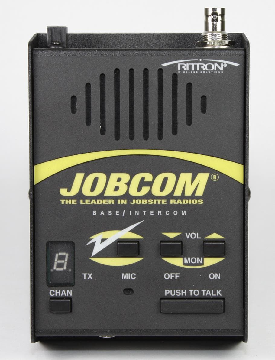
Click to zoom
Application Details
- Equipment Class
- TNB - Licensed Non-Broadcast Station Transmitter
- Date of Grant
- May 01, 2014
- Application Purpose
- Original Equipment
- Date of Application
- May 01, 2014
- Equipment Note
- VHF-FM Desk Top Transceiver
- Frequency Range
- 150.00000000 - 174.00000000
- Company
- Ritron Inc
- Country
- United States
Documents & Files
Document Text
Text extracted from the exhibit documents filed with the FCC. Open a document above to read the original.
Users Manual
Page 1 JBS-146i_UserMan.pdf TYPE OF EXHIBIT: INSTALLATION AND OPERATING INSTRUCTION MANUAL FCC PART: 2.1033 (c)(3) MANUFACTURER: RITRON, INC. MODELS: JBS-146i TYPE OF UNIT: VHF-FM 2-Way Desk Top Radio FCC ID: AIERIT37-146I DATE: April 29, 2014 Included in this exhibit is a draft copy of the User Manual for RITRON Model JBS-146i VHF-FM 2-Way Desk Top Radio. This manual provides the end user with installation and operating instructions. SIGNED: Michael A. Pickard - Project Engineer Have questions? Call 800-USA-1-USA (800-872-1872) or visit our website at www.ritron.com page 1 Display-Series Two-Way Base Station Owner’s Manual RUGGED, PROFESSIONAL TWO-WAY BASE RADIOS ALWAYS THERE...ALWAYS READY...ALWAYS ON SM 77 UHF and 19 VHF Table Frequencies for Easy Field Programming Built-in Quiet Call ® and Digital Quiet Call ® Interference Eliminator Up to 10 Channel Capability 12 VDC or Wall Outlet 120 VAC Operation NOAA Weather Channel Feature (VHF only) Emergency Weather Alert Feature (VHF only) Easy-to-Hear High Audio Output Call Tone “Z” Button - Programmable Soft Key 2-Tone Encode / Decode DTMF ANl Encoding Channel Scan 2 Watts of Power 2013 FCC Narrowband Compliant ACCESSORIES Have questions? Call 800-USA-1-USA (800-872-1872) or visit our website at www.ritron.com page ii JBSK-12 RHD-6X 12-Volt Adapter Kit Behind the Ear Headset RHD-8X Single Earbud Ram-1545 Magnet-mounted Dual-band Antenna RSP-5 RM-7 5-Watt External Speaker Hand Microphone OPTIONAL REPLACEMENT ACCESSORIES: TO ORDER CALL 800-USA-I-USA AFB-1545 .... Molded Flex, Dual-band Replacement Antenna RAM-I545..... Magnet-mounted, Dual-band Antenna w / BNC RPS-IB ......... Replacement 110 VAC Power Supply CCL-M ......... 12 VDC, Cigarette Lighter Adaptor JBSK-I2 ....... 12 VDC, Adaptor Kit REP-2 .......... Low Profile Earphone RHD-IX......... Single Ear Headset RHD-4X........ Dual Ear Headset RHD-6X........ Lightweight Behind-the-head Earset w / In-line PTT RHD-8X........ Lightweight Earbud w / mic and In-line PTT RSM-3XA ..... Remote Speaker Microphone RM-7 ............ Hand Microphone & Hang-up Bracket RSP-5 .......... External Speaker w / 5 Watt Audio Capability JBS-MMK .... Mobile Mounting Kit (Does not include screws to mount bracket to wall or vehicle) Call RITRON for a complete listing. TABLE OF CONTENT Have questions? Call 800-USA-1-USA (800-872-1872) or visit our website at www.ritron.com page iii DESCRIPTION PAGE ACCESSORIES Optional Accessories ............................................ii INTRODUCTION “Display Series” Model Numbers .......................... 1 Basic Features ..................................................... 1 2013 FCC Narrowband Mandate .......................... 2 CONTROL & OPERATION .................................. 3 FIG-1: Radio Controls and Connectors ................. 3 OPERATION FIG-2: Volume Level Indicator .............................. 4 ON-OFF / Volume Adjust ..................................... 4 Channel Selection ................................................ 4 Receive ............................................................... 4 QC and DQC Tone Codes (Interference Eliminator Codes) ............................ 5 Squelch Modes .................................................... 5 Transmit .............................................................. 5 FIG-3: Transmit Busy Lamp ................................. 5 Radio Alert Tones ................................................ 6 Optional Alert Tones ............................................ 6 Channel Scan Operation ...................................... 7 2-Tone Decode Operation .................................... 8 FIG-4: 2-Tone Call Alert ....................................... 8 “Z” Button - Programmable Soft Key .................... 9 NOAA WEATHER RADIO FEATURE How to Select Your Local NOAA Weather Frequency ......................................................... 10 NOAA Weather Feature ..................................... 10 FIG-5: Selecting Your Local NOAA Weather Frequency ......................................................... 11 DESCRIPTION PAGE FIG-6: NOAA Frequencies ................................. 11 NOAA Weather Alert Feature ............................ 11 Using the “Z” Button to Access NOAA Weather .. 11 RADIO PROGRAMMING FIG-7: How to Place the Radio in Program / Readout Mode ................................................... 12 How to Readout Field Programmed Frequency & Tone Codes ................................... 12 How to Field Program Frequency and Tone Codes ....................................................... 13 Table 1: Programmable Frequency Codes.......... 14 Table 2: Programmable QC Tone Codes ............ 15 Table 3: Programmable DQC Codes .................. 15 How to Field Program Radio Feature Codes ....... 15 Table 4: Radio Feature Codes ............................ 15 How to Delete a Channel .................................... 16 PC Programmable Features ............................... 16 !! CAUTIONS —ALL RADIOS!! Observe Caution in the Following Environments to Maximize the Life of Your Radio Equipment .... 17 Exposure to Radio Frequency Energy ................ 17 TROUBLESHOOTING ....................................... 18 SPECIAL APPLICATION How to Field Program 2-Tone Encode Codes ..... 19 for GateGuard Applications, go to www.ritron.com/pdf/gg_07.pdf How to Send a 2-Tone Code .............................. 19 TABLE 5: Programmable 2-Tone Encode Code .. 19 DESCRIPTION PAGE FCC & IC LICENSE REQUIRED Licensing ............................................................20 Safety Standards ................................................20 How to Obtain an FCC Radio License .................20 Industry Canada Regulations ..............................20 Service ...............................................................20 LIMITED WARRANTY ......................................21 ADDENDUM TO MANUAL JBS-146i-A and JBS-446D-A Instructions Auto Turn On Wh…
Text truncated - open the document above for the full version.
Cover Letter(s)
Page 1 JBS-146i_Attest.pdf TYPE OF EXHIBIT: DESCRIPTION OF MEASUREMENT FACILITY FCC PART: 2.948 MANUFACTURER: RITRON, INC. MODELS: JBS-146i TYPE OF UNIT: VHF-FM 2-Way Desk Top Radio FCC ID: AIERIT37-146I DATE: April 29, 2014 The ERP and field strength of spurious emissions measurements filed with this application were made on a site certified by RITRON, Inc. Data pertaining to this site are on file with the FCC and Industry Canada. This site is used on a continuing basis exclusively by RITRON, Inc. and is utilized only for RF field strength measurements of equipment designed and manufactured by RITRON, Inc. It is not used for measurements by, or for, any other party on a contract basis or otherwise. All other measurements were taken at RITRON’s engineering laboratory in Carmel, IN. Signed: Michael A. Pickard - Project Engineer Page 2 JBS-146i_Attest.pdf TYPE OF EXHIBIT: MANUFACTURER’S STATEMENT FCC PART: 2.1033(c)(1)(2) MANUFACTURER: RITRON, INC. MODELS: JBS-146i TYPE OF UNIT: VHF-FM 2-Way Desk Top Radio FCC ID: AIERIT37-146I DATE: April 29, 2014 The RITRON model JBS-146i is designed for operation on 12.5 kHz channel bandwidths. Its output power can be adjusted up to 2.5 Watts, but is set at the factory to 2.0 Watts. FCC Part 90 certification will be for the extended frequency range of 150-174 MHz. Frequency programming of these radios must be performed by a licensed radio technician to assure conformance with Part 90 certification. There are no provisions for user programming on frequencies that are not available under FCC Part 90. This product will be manufactured and marketed on a continuing basis in the United States of America by the applicant, RITRON, Inc. of Carmel, IN. Signed: Michael A. Pickard - Project Engineer Page 3 JBS-146i_Attest.pdf TYPE OF EXHIBIT: STATEMENT OF CERTIFYING ENGINEER FCC PART: 2.947 MANUFACTURER: RITRON, INC. MODELS: JBS-146i TYPE OF UNIT: VHF-FM 2-Way Desk Top Radio FCC ID: AIERIT37-146I DATE: April 29, 2014 I, Michael A. Pickard, have been employed by RITRON, Inc. since November 1979, working in the Engineering Department since June 1981 as a radio frequency Project Engineer. I hereby certify that all the measurements and data herein were taken by me, or under my direct supervision and that they were obtained using sound and accepted engineering principles and that they accurately reflect the performance and characteristics of the unit tested. Further, I attest that manufacturing controls exist such that this data are representative of units which will be manufactured by RITRON. Signed: Michael A. Pickard - Project Engineer Page 4 JBS-146i_Attest.pdf TYPE OF EXHIBIT: ANTI-DRUG ABUSE CERTIFICATION FCC PART: MANUFACTURER: RITRON, INC. MODELS: JBS-146i TYPE OF UNIT: VHF-FM 2-Way Desk Top Radio FCC ID: AIERIT37-146I DATE: April 29, 2014 I, Michael A. Pickard, certify that RITRON is not subject to a denial of Federal benefits, that include FCC benefits, pursuant to Section 5301 of the Anti-Drug Abuse Act of 1988, 21 U.S.C. 862 because of a conviction for possession or distribution of a controlled substance. Signed: Michael A. Pickard - Project Engineer
Cover Letter(s)
Page 1 JBS-146i_ConfidReq.pdf Ritron, Incorporated 505 W. Carmel Drive · Carmel, IN 46032 P. O. Box 1998 · Carmel, IN 46082 Ph: 317-846-1201 Email: [email protected] Web Site: www.ritron.com April 29, 2014 Ritron Inc. 505 West Carmel Dr. Carmel, IN 46032 Federal Communications Commission Authorization and Evaluation Division Confidentiality Request regarding application for certification of FCC ID: AIERIT37-146I Pursuant to Sections 0.457 and 0.459 of the Commission’s Rules, we hereby request long term confidential treatment of information accompanying this application as outlined below: Exhibit Type File Name Block Diagram Schematics Operational Description Semiconductor List Tune-up Procedure JBS-146i_BlkDia.pdf JBS-146i _Schem.pdf JBS-146i _OpDes.pdf JBS-146i _PartsLst.pdf JBS-146i _TunPro.pdf The above materials contain trade secrets and proprietary information not customarily released to the public. The public disclosure of these materials may be harmful to the applicant and provide unjustified benefits to its competitors. The applicant understands that pursuant to Section 0.457 of the Rules, disclosure of this application and all accompanying documentation will not be made before the date of the Grant for this application. Sincerely, Sam L. Dulaney Chief Engineer Ritron, Inc. Email: [email protected]
Cover Letter(s)
Page 1 JBS-146i_FreqJust.pdf Ritron, Incorporated 505 W. Carmel Drive · Carmel, IN 46032 P. O. Box 1998 · Carmel, IN 46082 Ph: 317-846-1201 Email: [email protected] Web Site: www.ritron.com April 30, 2014 Office of Engineering and Technology Laboratory Division Equipment Authorization Branch FCC Laboratory7435 Oakland Mills Rd. Columbia, MD 21046 Re: Extended Frequency Justification on FCC ID: AIERIT37-146I To whom it may concern: The JBS-146i two-way desktop radio was designed to operate in the frequency band 150-174 MHz. To aid equipment authorization in other countries within ITU regions 1, 2 or 3 which accept the United States FCC Grant for certification, Ritron is requesting that the FCC lists the frequencies 150-174 MHz under FCC Rule Parts 90 on the FCC Grant. This product is also intended for Federal end users. For the FCC’s Rule Part 90 applications, this radio is used in systems by OEM systems integrators as indicated in the table below. Equipment programming is the responsibility of Authorized Service Personnel. Also, the radio complies with 47 CFR Part 90.203(e) in that the operator cannot directly program the transmit frequencies using the normally accessible external controls. Per the FCC’s KDB634817 guidance, “as an alternative to listing the exact frequencies, we acknowledge that it’s a violation of the FCC Rules if this device operates on unauthorized frequencies.” Frequency Range (MHz) Part 90 Federal Customers/ Not Part 90 Grant Notes Emission Designator Part 90 150.0000 - 150.8000 x EF 11K0F3E 150.8000 - 156.2475 x EF 11K0F3E 156.2475 - 157.1875 x EF 11K0F3E 157.1875 - 161.5750 x EF 11K0F3E 161.5750 - 161.7750 x EF 11K0F3E 161.7750 - 173.4000 x EF 11K0F3E 173.4000 - 174.0000 x EF 11K0F3E Sincerely, Sam L. Dulaney Chief Engineer Ritron, Inc. Email: [email protected]
External Photos
Page 1 JBS-146i_ExtPho.pdf TYPE OF EXHIBIT: EXTERNAL PHOTOGRAPHS FCC PART: 2.1033(c)(12) MANUFACTURER: RITRON, INC. MODELS: JBS-146i TYPE OF UNIT: VHF-FM 2-Way Desk Top Radio FCC ID: AIERIT37-146I DATE: April 29, 2014 Included in this exhibit are photographs of the RITRON Model JBS-146i case assembly. Additional photographs of the radio printed circuit board construction and installation are included with this certification request as separate exhibits. SIGNED: Michael A. Pickard - Project Engineer Page 2 JBS-146i_ExtPho.pdf EXHIBIT: JBS-146i top view showing controls FCC ID: AIERIT37-146I Page 3 JBS-146i_ExtPho.pdf EXHIBIT: JBS-146i bottom view showing FCC label location (Photo shows label location only and does not represent the actual FCC label) FCC ID: AIERIT37-146I Page 4 JBS-146i_ExtPho.pdf EXHIBIT: JBS-146i front view showing external audio jacks FCC ID: AIERIT37-146I Page 5 JBS-146i_ExtPho.pdf EXHIBIT: JBS-146i rear view showing antenna connection and DC power connector FCC ID: AIERIT37-146I
ID Label/Location Info
Page 1 JBS-146i_LabelLoc.pdf TYPE OF EXHIBIT: FCC ID LABEL LOCATION FCC PART: 2.1033 MANUFACTURER: RITRON, INC. MODELS: JBS-146i TYPE OF UNIT: VHF-FM 2-Way Desk Top Radio FCC ID: AIERIT37-146I DATE: April 29, 2014 Photograph indicates the location of the FCC label on the case and does not represent the actual FCC label. A label drawing is included with this certification request as a separate exhibit. SIGNED: Michael A. Pickard - Project Engineer
ID Label/Location Info
Page 1 JBS-146i_LabelSmpl.pdf TYPE OF EXHIBIT: FCC ID LABEL SAMPLE FCC PART: 2.1033 MANUFACTURER: RITRON, INC. MODELS: JBS-146i TYPE OF UNIT: VHF-FM 2-Way Desk Top Radio FCC ID: AIERIT37-146I DATE: April 29, 2014 Ritron drawing 14200204A specifies the FCC label for model JBS-146i. Photographs to indicate the position of the label on the case are included with this certification request as a separate exhibit. Each serial number is recorded, along with the date of manufacture, and is kept on file at RITRON, Inc. Serialization will begin with serial number E1234. The size of the serial label is 3.00” by 2.00”. SIGNED: Michael A. Pickard - Project Engineer Page 2 JBS-146i_LabelSmpl.pdf RITRON, INC. 505 West Carmel Drive Carmel, Indiana 46032 TEL: 317-846-1201 FAX: 317-846-4978 http://www.ritron.com RITRON ITEM: 14200204A DESCRIPTION: LABEL, FCC/IC/SERIAL, JBS VENDOR PART NUMBERS: Identco# TTL307-700, Identco# TTRR-D3.54ZJ REVISION DATE: March 21, 2014 DESCRIPTION: The FCC/IC serial label will be made in house by manufacturing. The ELP 310 thermal transfer printer will be used with glossy white polyester labels (RTN# 14290001). Identco# TTL307-700, a three (3) inch by two (2) inch label, is the approved material. The approved ribbon is Identco# TTRR-D3.54ZJ. Labels will be numbered sequentially, with an initial 5-digit number of E1234. Records are maintained to track the next available serial number. All models listed share the same serial sequence, and are identical except for model identification. Each label will contain an updated Manufacturing Date using the Ritron 4- digit Date Code (YEAR/WEEK). Standard label drawing using JBS-146i as an example. Chief Eng: ________________ Project Eng: ________________ Sales: ________________ Manufacturing: ________________ This radio requires Ritron PC Programmer 9.6.0 or higher. FCC: AIERIT37-146I IC: FREQ: 150-174 MHz MODEL: JBS-146i SN: E1234 Mfg Date: 1412 Use of this radio device must be monitored to assure FCC and Industry Canada RF exposure compliance. See owner’s manual for specific operating instructions. For service, contact your radio dealer or return product directly to: RITRON, INC. 505 W. CARMEL DR. CARMEL, IN 46032 OR CALL 1-800-USA-1-USA www.ritron.com Made in the USA
Internal Photos
Page 1 JBS-146i_IntPho.pdf TYPE OF EXHIBIT: INTERNAL PHOTOGRAPHS FCC PART: 2.1033(c)(12) MANUFACTURER: RITRON, INC. MODELS: JBS-146i TYPE OF UNIT: VHF-FM 2-Way Desk Top Radio FCC ID: AIERIT37-146I DATE: April 29, 2014 Included in this exhibit are photographs of the RITRON Model JBS-146i printed circuit board assembly and installation. Additional photographs of the radio construction and layout, labels, and chassis assembly are included with this certification request as separate exhibits. SIGNED: Michael A. Pickard - Project Engineer Page 2 JBS-146i_IntPho.pdf EXHIBIT: JBS-146i complete bottom side PCB assembly with shields removed FCC ID: AIERIT37-146I Page 3 JBS-146i_IntPho.pdf EXHIBIT: JBS-146i complete top side PCB assembly FCC ID: AIERIT37-146I Page 4 JBS-146i_IntPho.pdf EXHIBIT: JBS-146i with case open to show printed circuit board installation FCC ID: AIERIT37-146I
RF Exposure Info
Page 1 JBS-146i_RFExp.pdf TYPE OF EXHIBIT: TRANSMITTER EFFECTIVE RADIATED POWER FCC PART: 1.1310 MANUFACTURER: RITRON, INC. MODELS: JBS-146i TYPE OF UNIT: VHF-FM 2-Way Desk Top Radio FCC ID: AIERIT37-146I DATE: April 30, 2014 PROCEDURE: 1. The measurements for effective radiated power were taken at the RITRON, Inc. 3-meter test site, details of which are on file with the FCC. These measurements were via the substitution method. 2. The JBS-146i was aligned for transmitter operation on 3 frequencies represent the low, middle, and upper range of the desired operating band at the rated 2.5W transmitter output power. The JBS-146i was terminated at the antenna port with the Ritron AFB-1545 antenna include with the product. (The user can connect other antennas, however.) 3. The ERP measurements were made with an Advantest R3265A Spectrum Analyzer and an Electro- Metrics BDA-25 dipole antenna. 4. The height of the BDA-25 receiving antenna and orientation of the JBS-146i were varied to provide maximum field strength at the receiving antenna. 5. A calibrated ½-wave dipole antenna was substituted for the JBS-146i on the turntable 3 meters from the pick up antenna. An HP 8657B RF signal generator was set at the 3 frequencies representing the low, middle and upper range of the desired operating band with a 0 dBm output level. 6. The height of the BDA-25 receiving antenna was adjusted for maximum signal strength at the receiving antenna. The level at the field strength antenna was noted. Page 2 JBS-146i_RFExp.pdf TYPE OF EXHIBIT: TRANSMITTER EFFECTIVE RADIATED POWER FCC PART: 1.1310 MANUFACTURER: RITRON, INC. MODELS: JBS-146i TYPE OF UNIT: VHF-FM 2-Way Desk Top Radio FCC ID: AIERIT37-146I DATE: April 30, 2014 CALCULATIONS: The effective radiated power can be calculated as: ERP(dBm) = Pr(dBm) -- Pref(dBm) + Pgen(dBm)) – Ga(dBd) Where: Pr is the power level of the radio’s emission at the receiving antenna output. Pgen is the RF signal generator level at the substitution antenna input. Pref is the power level of the substitution antenna emission at the receiving antenna output. Ga is the gain of the substitution antenna. Maximum radiated power occurred with the JBS-146i and AFB-1545 antenna at the highest RF test frequency: ERP(dBm) = 8.86 – (-24.79) + (-1.13) – 0.2 = 32.31 dBm ERP(watts) = antilog((ERP(dBm) – 30)/10) ERP(watts) = 1.703 Watts Frequency Pr Pref Pgen Ga ERP ERP (MHz) (dBm) (dBm) (dBm) (dBd) (dBm) (watts) 150.815 3.88 -1.24 -23.39 0.2 25.83 0.383 163.250 8.48 -1.16 -21.69 0.2 28.82 0.762 173.390 8.86 -1.13 -24.79 0.2 32.31 1.703 Signed: Michael A. Pickard - Project Engineer Page 3 JBS-146i_RFExp.pdf TYPE OF EXHIBIT: MAXIMUM PERMISSABLE EXPOSURE EVALUATION FCC PART: 2.1091(d)(4) MANUFACTURER: RITRON, INC. MODELS: JBS-146i TYPE OF UNIT: VHF-FM 2-Way Desk Top Radio FCC ID: AIERIT37-146I DATE: April 30, 2014 PROCEDURE AND EQUATIONS: The ERP values previously calculated will be used to determine the minimum safe distance from the antenna supplied by RITRON in order not to exceed the General Population/Uncontrolled Limits of RF exposure. The ERP must be converted to EIRP to simulate an isotropic radiator. Typical transmit duty cycles are between 5% and 10%. Over the 30 minute averaging period for General Population/Uncontrolled MPE limits, a 50% maximum duty cycle is reasonable, and will be used in the MPE calculations for this device. Since the unit is categorized as a portable radio, a 50% duty cycle may be used, therefore: EIRP = 1.64 (ERP/2) For the JBS-146i w/AFB-1545: EIRP = 1.396 W Power density is related to EIRP: S(W/m 2 ) = EIRP(W)/4r 2 where r is the distance from the source in meters. Rearranging for distance: r = SQRT (EIRP/4S). The MPE limit for this device operating in a General Population/Uncontrolled environment is 0.2 mW/ cm 2 For the equation above, mW/cm 2 must be converted to W/m 2 . Since 1 mW/cm 2 = 10 W/m 2 , the FCC limit is 2 W/m 2 . Substituting and solving for distance: Model /Antenna Distance for MPE (in. / cm) JBS-146i/AFB-1545 7.58 / 19.24 With the antenna available from RITRON for use with this product, users must remain more than 7.58 inches (19.24 cm) from the AFB-1545 antenna while the unit is transmitting. For the AFB-1545 antenna, the minimum expected separation of 20 cm (7.9 inches) results in RF exposure levels well below the General Population/Uncontrolled MPE limits. Other antenna may require lesser or greater distances depending upon their gain relative to that available from RITRON. Page 4 JBS-146i_RFExp.pdf TYPE OF EXHIBIT: RF WARNING STATEMENT FCC PART: 1.1310 MANUFACTURER: RITRON, INC. MODELS: JBS-146i TYPE OF UNIT: VHF-FM 2-Way Desk Top Radio FCC ID: AIERIT37-146I DATE: April 30, 2014 WARNING STATEMENT: The following statement appears in the Users Manual: PLEASE NOTE THE FOLLOWING WITH REGARD TO RF EXPOSURE FOR THIS PRODUCT: EXPOSURE TO RADIO FREQUENCY ENERGY: JBS-146i: This product generates radio frequency (RF) energy when the PTT button on the top of the unit is depressed. This product has been evaluated for compliance with the maximum permissible exposure limits for RF energy at the maximum power rating of the unit when using antennas available from RITRON. For the AFB-1545 at the 20 cm (7.9 inches) minimum expected separation distance and greater, the maximum RF exposure is well below the General Population/Uncontrolled limits. Antennas other than those available from RITRON have not been tested for compliance and may or may not meet the exposure limits at the distances given. Higher gain antennas are capable of generating higher fields in the strongest part of their field and would, therefore, require a greater separation from the antenna. This product is not to be used by the general public in an uncontrolled environment unless compliance with the Uncontrolled/General Population limits for RF exposure can be assured. To limit exposure to RF energy to levels below the limit, please observe the following: • Use only the antenna(s) available fr…
Text truncated - open the document above for the full version.
Test Report
TYPE OF EXHIBIT: TABLE OF CONTENTS FCC PART: MANUFACTURER: RITRON, INC. MODELS: JBS-146i TYPE OF UNIT: VHF-FM 2-Way Desk Top Radio FCC ID: AIERIT37-146I DATE: April 29, 2014 Following is a list of exhibits required by the Federal Communications Commission for the application to and grant of FCC Certification. File / Exhibit FCC Part JBS-146i_731Form.pdf Timco Form 731 ............................................................................................................ 2.1033 (a) JBS-146i_ConfidReq.pdf Letter of request for confidentiality ................................................................................ 0.457, 0.459 JBS-146i_FreqJust.pdf Extended Frequency Justification Letter ........................................................................ JBS-146i_Attest.pdf Description of Measurement Facility ............................................................................. 2.948 Manufacturer’s Statement ............................................................................................. 2.1033 (c) (1-2) Statement of Certifying Engineer................................................................................... 2.947 Anti-Drug Abuse Certification ........................................................................................ JBS-146i_RFExp.pdf Transmitter Effective Radiated Power ........................................................................... 1.1310 Maximum Permissible Exposure Evaluation .................................................................. 2.1091 (d) (4) RF Warning Statement .................................................................................................. 1.1310 JBS-146i_BlkDia.pdf Block Diagram .............................................................................................................. 2.1033 (b) (5) JBS-146i_Schem.pdf Schematic Drawings ..................................................................................................... 2.1033 (c) (10) JBS-146i_IntPho.pdf Internal Photographs ..................................................................................................... 2.1033 (c) (12) JBS-146i_ExtPho.pdf External Photographs.................................................................................................... 2.1033 (c) (12) JBS-146i_LabelLoc.pdf FCC ID Label Location .................................................................................................. 2.1033 (c) (11) JBS-146i_LabelSmpl.pdf FCC ID Label Sample ................................................................................................... 2.1033 (c) (11) JBS-146i_OpDes.pdf Operational Description ................................................................................................. 2.1033 (c) (4, 5, 7, 8, 10) JBS-146i_TunePro.pdf Tune-Up Procedure ...................................................................................................... 2.1033 (c) (9) JBS-146i_PartsLst.pdf Semiconductor Function ............................................................................................... 2.1033 (b) (4) JBS-146i_TestRpt.pdf List of Test Equipment Used ......................................................................................... 2.947 (d) Description of Measurement Facility ............................................................................. 2.947 (d) Radio Frequency Power Output .................................................................................... 2.1046 (a) Transmitter Audio Overall Response ............................................................................. 2.1047 (a) Transmitter Audio Lowpass Filter .................................................................................. 2.1047 (a) Modulation Limiting ....................................................................................................... 2.1047 (b) Emissions Designator ................................................................................................... 2.1049 (c) Occupied Bandwidth ..................................................................................................... 2.1049 (c) (1), 90.210 (d) Spurious Emissions at Antenna Terminals .................................................................... 2.1051 Field Strength of Spurious Emissions ............................................................................ 2.1053 (b) Frequency Stability vs. Temperature ............................................................................. 2.1055 (a) (1) Frequency Stability vs. Battery Voltage ......................................................................... 2.1055 (d) Transient Frequency Behavior ...................................................................................... 90.214 JBS-146i_UserMan.pdf Installation and Operating Instruction Manual ................................................................ 2.1033 (c) (3)
Test Report
Page 1 JBS-146i_TestRpt.pdf TYPE OF EXHIBIT: TEST REPORT FCC PART: 2.1033 (c)(14) MANUFACTURER: RITRON, INC. MODELS: JBS-146i TYPE OF UNIT: VHF-FM 2-Way Desk Top Radio FCC ID: AIERIT37-146I DATE: April 30, 2014 The following is a list of attached exhibits required by the Federal Communications Commission for the application to and grant of FCC Type Acceptance. All tests are per TIA-603-D (2010) where applicable. TABLE OF CONTENT: EXHIBIT FCC PART(S) PAGE Test Equipment List 2.947 (d) pg 2 Description of Measurement Facility 2.947 (d) pg 3 Radio Frequency Power Output 2.1046 (a) pg 4 Transmitter Audio Overall Response 2.1047 (a) pg 5-6 Transmitter Audio Lowpass Filter 2.1047 (a) pg 7-8 Modulation Limiting 2.1047 (b) pg 9-10 Emissions Designator 2.1049 (c)(1) pg 11 Occupied Bandwidth 2.1049 (c)(1), 90.210(d) pg 12-13 Spurious Emissions at Antenna Terminals 2.1051 pg 14 Field Strength of Spurious Emissions 2.1053 pg 15-16 Frequency Stability vs. Temperature 2.1055 (a)(1) pg 17-20 Frequency Stability vs. Voltage 2.1055 (d)(1) pg 21 Transient Frequency Behavior 90.214 pg 22-25 Page 2 JBS-146i_TestRpt.pdf TYPE OF EXHIBIT: TEST EQUIPMENT LIST FCC PART: 2.947 (d) MANUFACTURER: RITRON, INC. MODELS: JBS-146i TYPE OF UNIT: VHF-FM 2-Way Desk Top Radio FCC ID: AIERIT37-146I DATE: April 22, 2014 TEST EQUIPMENT: The measured data in this report was obtained using one or more of the following pieces of equipment. The particular equipment used in any one test is detailed in the procedure for that test. ITEM MANUFACTURER MODEL NO. SERIAL NO. Last Cal EXP Cal Comms Test Set Aeroflex IFR COM-120B 485001757 6 DEC 2013 6 DEC 2014 Signal generator Hewlett-Packard 8657B 3315V04378 18 APR 2014 18 APR 2015 Spectrum Analyzer Advantest R3265A 75060189 02 OCT 2013 02 OCT 2014 Log Periodic Antenna Electro-Metrics LPA-25 8-102 17 MAY 2011 17 MAY 2014 Dipole Antenna Electro-Metrics BDA-25 8-101 17 MAY 2011 17 MAY 2014 Dipole Antenna Electro-Metrics EM-6925 292 8 APR 2014 8 APR 2015 Dipole Antenna Electro-Metrics EM-6927 292 8 APR 2014 8 APR 2015 Gain horn EMCO 3105 2034 22 OCT 2013 22 OCT 2015 SUPPORT EQUIPMENT: ITEM MANUFACTURER MODEL NO. SERIAL NO. …
Text truncated - open the document above for the full version.
Contact Information
Applicant
Sam L. Dulaney(Chief Engineer)
Test Firm
RITRON, Inc.Sam Dulaney
Technical Specifications
| # | Rule Parts | Frequency Range | Power Output | Emission | Tolerance |
|---|---|---|---|---|---|
| 1 | 90 | 150 MHz - 174 MHz | 2.5 W | 11K0F3E | 1.5000000000 ppm |
Other Applications from Ritron Inc

AIERIT53-16006
Jan 04, 2023VHF Transceiver
Equipment Class
TNB - Licensed Non-Broadcast Station Transmitter
AIERIT39-26006
Aug 26, 2021VHF Modem Transceiver
Equipment Class
TNB - Licensed Non-Broadcast Station Transmitter
AIERIT51-46530
Jul 25, 2021UHF Transceiver
Equipment Class
TNB - Licensed Non-Broadcast Station Transmitter
AIERIT50-477DMR
Feb 01, 2021UHF DMR Digital / Analog 2-Way Desktop Radio
Equipment Class
TNB - Licensed Non-Broadcast Station Transmitter
AIERIT51-16006
Jan 19, 2021VHF Transceiver
Equipment Class
TNB - Licensed Non-Broadcast Station Transmitter