AJDK029Media Center Receiver
Pioneer Corporation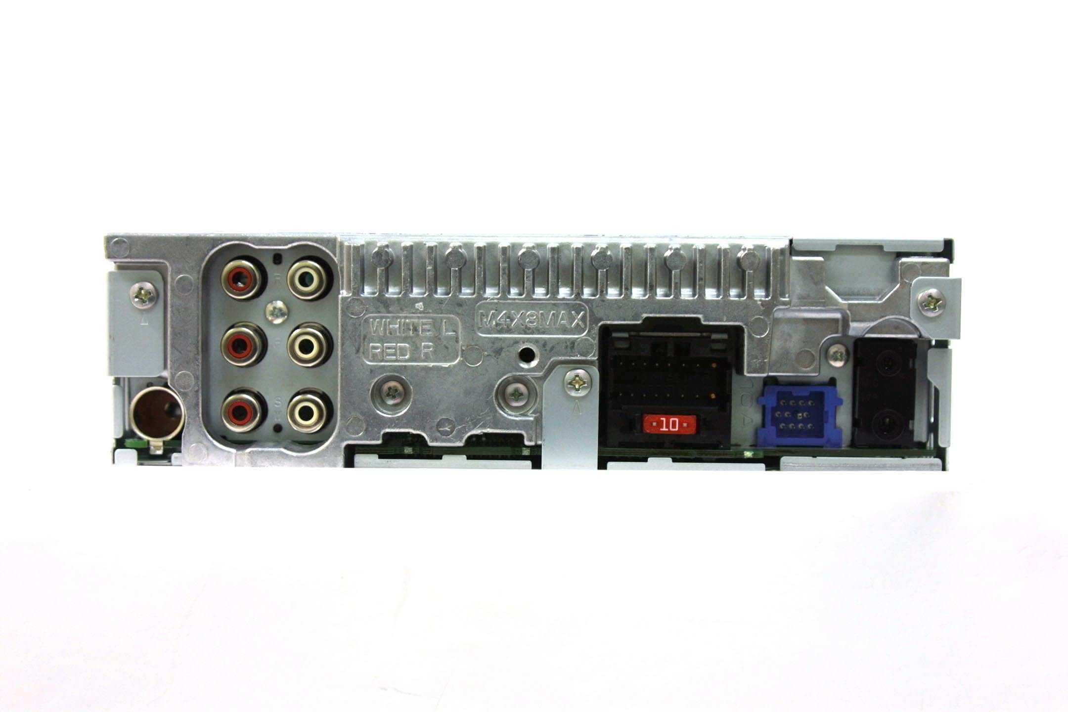
Click to zoom
Application Details
- Equipment Class
- DSS - Part 15 Spread Spectrum Transmitter
- Date of Grant
- Feb 03, 2010
- Application Purpose
- Original Equipment
- Date of Application
- Feb 03, 2010
- Equipment Note
- Media Center Receiver
- Frequency Range
- 2402.00000000 - 2480.00000000
- Company
- Pioneer Corporation
- Country
- Japan
Documents & Files
Document Text
Text extracted from the exhibit documents filed with the FCC. Open a document above to read the original.
Users Manual
<CRD4471-A> <1> Operation Manual Mode d’emploi Manual de instrucciones MEDIA CENTER RECEIVER AUTORADIO MULTIMEDIA RECEPTOR Y CENTRO DE COMUNICACIONES MVH-P8200BT MVH-P8200 English Français Español Black plate (2,1) Thank youfor purchasing this PIONEER product. To ensure proper use, please read through this manual before using this product. It is especially important that you read and observeWARNINGs andCAUTIONsin this manual.Please keep the manual in a safe and accessible place for future refer- ence. Precautions IMPORTANT SAFEGUARDS4 To ensure safe driving4 –Parking brake interlock5 To avoid battery exhaustion5 Before You Start MVH-P82006 Information to User6 For Canadian model6 About this unit6 Operating environment6 After-sales service for Pioneer products7 In case of trouble7 Visit our website7 Resetting the microprocessor7 Demo mode7 About this manual8 Operating this unit Head unit9 Remote control9 Basic Operations10 Use and care of the remote control11 Basic menu operations12 –Menu operations identical for function settings/audio adjustments/initial settings/lists12 Customizing menus12 –Canceling a Registered Menu13 About guide information13 Using Bluetooth telephone13 –Setting up for hands-free phoning13 –Basic Operations14 Radio14 –Basic Operations14 –Storing and recalling stations14 –Using iTunes tagging15 –Function settings15 Playing moving images16 –Basic Operations16 –Selecting and playing files from the name list17 –Browsing for a video on the iPod17 –Playing DivXâVOD content18 –Function settings18 Playing audio21 –Basic Operations21 –Selecting and playing files/tracks from the name list22 –Browsing for a song on the iPod22 –Function settings22 Playing still images24 –Basic Operations24 –Selecting and playing files from the name list24 –Function settings24 –Introduction of operations for playback of still images as a slideshow25 Bluetooth Telephone26 –Connection menu operation26 –Phone menu operation27 –Function and operation28 Audio Adjustments29 System settings30 Entertainment settings31 –Customizing the illumination color32 Initial Settings32 –Auto EQ (auto-equalizing)33 Other Functions35 –Using an AUX source35 –Using an external unit36 –Using the PGM button36 –Switching the display indication37 Detailed instructions Changing the wide screen mode38 Setting the DivX subtitle file38 Setting the aspect ratio38 <CRD4471-A/N>2 Contents En 2 Black plate (3,1) Displaying the DivXâVOD registration code39 Displaying the deactivation code39 Changing the picture adjustment39 Available accessories HD Radioätuner40 –Basic Operations40 –Storing and recalling stations40 –Using iTunes tagging40 –Function settings40 XM tuner40 –Basic Operations41 –Storing and recalling stations41 –Selecting an XM channel directly41 –Function settings41 –Selecting a channel from a channel category42 –Displaying the Radio ID42 SIRIUS Satellite Radio tuner42 –Basic Operations42 –Storing and recalling stations43 –Selecting a SIRIUS channel directly43 –Function settings43 –Selecting a channel from a channel category44 –Using the Instant Replay function44 Additional Information Troubleshooting45 Error messages45 Understanding auto EQ error messages48 Indicator list48 Handling guideline49 Compressed audio/video compatibility (USB, SD)51 iPod compatibility52 Sequence of audio files52 Using the display correctly53 –Handling the display53 –Liquid crystal display (LCD) screen53 –LED (light-emitting diode) backlight53 –Fluorescent tube53 Copyright and trademark54 Specifications56 <CRD4471-A/N>3 En 3 English Contents Black plate (4,1) IMPORTANT SAFEGUARDS Please read all of these instructions regarding your display and retain them for future refer- ence. 1Read this manual fully and carefully be- fore operating your display. 2Keep this manual handy as a reference for operating procedures and safety informa- tion. 3Pay close attention to all warnings in this manual and follow the instructions care- fully. 4Do not allow other persons to use this sys- tem until they have read and understood the operating instructions. 5Do not install the display where it may (i) obstruct the driver’s vision, (ii) impair the performance of any of the vehicle’s oper- ating systems or safety features, includ- ing air bags, hazard lamp buttons or (iii) impair the driver’s ability to safely oper- ate the vehicle. 6Do not operate this display if doing so in any way will divert your attention from the safe operation of your vehicle. Always observe safe driving rules and follow all existing traffic regulations. If you experi- ence difficulty in operating the system or reading the display, park your vehicle in a safe location and make necessary adjust- ments. 7Please remember to wear your seat belt at all times while operating your vehicle. If you are ever in an accident, your injuries can be considerably more severe if your seat belt is not properly buckled. 8Never use headphones while driving. 9To promote safety, certain functions are disabled unless the parking brake is on, and the vehicle is not in motion. 10Never set the volume of your display so high that you cannot hear outside traffic and emergency vehicles. WARNING !Do not attempt to install or service your display by yourself. Installation or servi- cing of the display by persons without training and experience in electronic equipment and automotive accessories may be dangerous and could expose you to the risk of electric shock or other hazards. To ensure safe driving WARNING !LIGHT GREEN LEAD AT POWER CON- NECTOR IS DESIGNED TO DETECT PARKED STATUS AND MUST BE CON- NECTED TO THE POWER SUPPLY SIDE OF THE PARKING BRAKE SWITCH. IM- PROPER CONNECTION OR USE OF THIS LEAD MAY VIOLATE APPLICABLE LAW AND MAY RESULT IN SERIOUS IN- JURY OR DAMAGE. !To avoid the risk of damage and injury and the potential violation of applicable laws, this unit is not for use with video that is visible to the driver. !To avoid the risk of accident and the potential violation of applicable laws, no viewing of front…
Text truncated - open the document above for the full version.
External Photos
Pioneer Corporation MEDIA CENTER RECEIVER Model: MVH- P8200BT FCC ID: AJDK029 IC Number: 775E-K029 External Photo Front Rear Pioneer Corporation MEDIA CENTER RECEIVER Model: MVH- P8200BT FCC ID: AJDK029 IC Number: 775E-K029 External Photo Top Bottom Pioneer Corporation MEDIA CENTER RECEIVER Model: MVH- P8200BT FCC ID: AJDK029 IC Number: 775E-K029 External Photo Right Left
ID Label/Location Info
Label Location
Internal Photos
Pioneer Corporation MEDIA CENTER RECEIVER FCC ID: AJDK029 IC Number: 775E-K029 Internal Photo Side A with Shield *Note: Bluetooth Board (Model: CK5000New) has two FCC IDs. CK5000New with internal antenna is FCC ID: RKXCK5000NVIA. CK5000New with external antenna is FCC ID: RKXCK5000NEA. This MEDIA CENTER RECEIVER installs CK5000New with external antenna. Side A without Shield Pioneer Corporation MEDIA CENTER RECEIVER FCC ID: AJDK029 IC Number: 775E-K029 Internal Photo Side B Antenna Position
RF Exposure Info
UL Japan, Inc. YAMAKITA EMC LAB. 907 Kawanishi, Yamakita-machi, Ashigarakami-gun, Kanagawa-ken, 258-0124 JAPAN Telephone: +81 465 77 1011 Facsimile: +81 465 77 2112 Applicant: PIONEER CORPORATION Type of Equipment : MEDIA CENTER RECEIVER M odel No. : M VH-P8200BT FCC ID: AJDK029 PIONEER CORPORATION declares that M odel : M EDIA CENTER RECEIVER complies with FCC radiation exposure requirement specified in the FCC Rules 2.1091. The “MVH-P8200BT“ has 1.13 mW of conducted Peak Output power and 0.95 mW of EIRP. This equipment is considered as a mobile device so that SAR testing is excluded. The Following calculation is the reference data for 20cm distance. RF Exposure Calculations: The following information provides the minimum separation distance for the highest gain antenna provided with the “MVH-P8200BT“ as calculated from FCC OET Bulletin 65 Appendix A, Table (B) Limits for General Population / Uncontrolled Exposure. This calculation is based on the highest EIRP possible from the system, considering maximum power and antenna gain, and considering a 1.0mW/cm^2 uncontrolled exp o su re lim it. T he F riis fo rm u la u sed w as: S = (P * G) / (4* π * r 2 ) Where P = 1.13 mW (M aximum peak output power) G = 0.84 Numerical Antenna gain; equal -0.75 dBi r =20.0 cm For: M VH-P8200BTS = 0.00019 mW/cm 2 No. : 30CE0242-YK-01-A RF Exposure / SAR Statement
Test Report
FCC ID : AJDK029 Test report No. : 30CE0242-YK-01-A Page : 2 of 50 Issued date : January 27, 2010 UL Japan, Inc. Yamakita EMC Lab. 907 Kawanishi, Yamakita-machi, Ashigarakami-gun, Kanagawa-ken, 258-0124 JAPAN Telephone: +81 465 77 1011 Facsimile: +81 465 77 2112 Table of Contents Page 1 Applicant information 3 2 Equipment under test (E.U.T.) 4 3 Test specification, procedures and results 5 4 System test configuration 7 5 Carrier frequency separation 9 6 20dB bandwidth & Occupied bandwidth (99%) 9 7 Number of hopping frequency 9 8 Dwell time 9 9 Maximum peak output power 9 10 Out of band emissions (Antenna port conducted) 9 11 Out of band emissions (Radiated) 10 Contents of Appendixes 11 APPENDIX 1: Photographs of test setup 12 APPENDIX 2: Test data 13 APPENDIX 3: Test instruments 50 FCC ID : AJDK029 Test report No. : 30CE0242-YK-01-A Page : 3 of 50 Issued date : January 27, 2010 UL Japan, Inc. Yamakita EMC Lab. 907 Kawanishi, Yamakita-machi, Ashigarakami-gun, Kanagawa-ken, 258-0124 JAPAN Telephone: +81 465 77 1011 Facsimile: +81 465 77 2112 1 Applicant information Company Name : PIONEER CORPORATION Address : 25-1 Nishi-machi, Yamada-aza, Kawagoe-shi, Saitama, 350-8555, JAPAN Telephone Number : +81 49 228 6274 Facsimile Number : +81 49 228 6497 Contact Person : Toru Yamashita FCC ID : AJDK029 Test report No. : 30CE0242-YK-01-A Page : 4 of 50 Issued date : January 27, 2010 UL Japan, Inc. Yamakita EMC Lab. 907 Kawanishi, Yamakita-machi, Ashigarakami-gun, Kanagawa-ken, 258-0124 JAPAN Telephone: +81 465 77 1011 Facsimile: +81 465 77 2112 2 Equipment under test (E.U.T.) 2.1 Identification of E.U.T. Type of Equipment : MEDIA CENTER RECEIVER Model No. : MVH-P8200BT Serial No. : Refer to 4.2 in this report. Rating : DC14.4V Country of Mass-production : Thailand Condition of EUT : Production prototype (Not for Sale: This sample is equivalent to mass-produced items.) Modification of EUT : No modification by the test lab. Receipt Date of Sample : December 7, 2009 2.2 Product description Model: MVH-P8200BT (referred to as the EUT in this report) is a MEDIA CENTER RECEIVER. Clock frequency: (1) FM/AM TUNER: 39.9MHz (2) DC-DC CONVERTER: 365.78kHz/425.10kHz (3) SYSTEM MICRO COMPUTER: 3.93216MHz (4) SD/USB DECODER: 27MHz, 48MHz, 33.8688MHz (5) DISPLAY CONVERTER: 9.597MHz, 33MHz (6) Blue tooth module OSC: 26MHz (7) LCD BACK LIGHT DRIVER: 476.63kHz/ 524.29kHz (8) Electrical volume IC DRIVER: 476.63kHz/ 524.29kHz Equipment type : Transceiver Frequency of operation : 2402-2480MHz Bandwidth & channel spacing : 79MHz & 1MHz Type of modulation : FHSS Antenna type : Pattern Antenna gain with cable loss : -0.75dBi Antenna connector type : Micro coaxial (I-PEX: 20279 type) ITU code : 79M0F1D Operation temperature range : -10 to +60 deg.C. FCC Part15.31 (e) The equipment provides the Bluetooth transmitter with stable power supply (DC 3.3 V), therefore, the equipment complies power supply regulation. FCC Part15.203 Antenna requirement The equipment and its antenna comply with this requirement since this antenna is built in the equipment and it cannot be replaced by end users. FCC ID : AJDK029 Test report No. : 30CE0242-YK-01-A Page : 5 of 50 Issued date : January 27, 2010 UL Japan, Inc. Yamakita EMC Lab. 907 Kawanishi, Yamakita-machi, Ashigarakami-gun, Kanagawa-ken, 258-0124 JAPAN Telephone: +81 465 77 1011 Facsimile: +81 465 77 2112 3 Test specification, procedures and results 3.1 Test specification Test specification : FCC Part 15 Subpart C: 2009, final revised on December 2, 2009 Title : FCC 47CFR Part15 Radio Frequency Device Subpart C Intentional Radiators Section 15.207 Conducted limits Section 15.209 Radiated emission limits, general requirements Section 15.247 Operation within the bands 902-928MHz, 2400-2483.5MHz, and 5725-5850MHz The EUT complies with FCC Part 15 Subpart B: 2009, final revised on December 2, 2009. The test has been performed by the customer. 3.2 Procedures & Results Item Test Procedure Specification Remarks DeviationWorst Margin Results Conducted emission ANSI C63.4:2003 7. AC powerline conducted emission measurements FCC Section 15.207 - N/A *1) N/A N/A Carrier frequency separation FCC Public Notice DA 00-705 & ANSI C63.4:2003 13. Measurement of intentional radiators FCC Section15.247 (a)(1) Conducted N/A Complied 20dB bandwidth FCC Public Notice DA 00-705 & ANSI C63.4:2003 13. Measurement of intentional radiators FCC Section15.247 (a)(1) Conducted N/A Complied Number of hopping frequency FCC Public Notice DA 00-705 & ANSI C63.4:2003 13. Measurement of intentional radiators FCC Section15.247 (a)(1)(iii) Conducted N/A Complied Dwell time FCC Public Notice DA 00-705 & ANSI C63.4:2003 13. Measurement of intentional radiators FCC Section15.247 (a)(1)(iii) Conducted N/A Complied Maximum peak output power FCC Public Notice DA 00-705 & ANSI C63.4:2003 13. Measurement of intentional radiators FCC Section15.247 (b)(1) Conducted N/A *See data. Complied Band edge compliance & Spurious emission FCC Public Notice DA 00-705 & ANSI C63.4:2003 13. Measurement of intentional radiators FCC Section15.247 (d) Section15.209 Conducted/ Radiated N/A 6.0dB (283.5MHz, Horizontal, Tx 2402MHz / Tx 2441MHz) Complied Note: UL Japan’s EMI Work Procedures No.QPM05 and QPM15. *1) The test is not applicable since the EUT has no AC mains. FCC ID : AJDK029 Test report No. : 30CE0242-YK-01-A Page : 6 of 50 Issued date : January 27, 2010 UL Japan, Inc. Yamakita EMC Lab. 907 Kawanishi, Yamakita-machi, Ashigarakami-gun, Kanagawa-ken, 258-0124 JAPAN Telephone: +81 465 77 1011 Facsimile: +81 465 77 2112 3.3 Addition to standard Item Test Procedure Specification Remarks Worst Margin Results Occupied bandwidth (99%) ANSI C63.4:2003 13. Measurement of intentional radiators RSS-Gen 4.6.1 RSS-Gen 4.6.1 Conducted- Complied * Other than above, no addition, exclusion nor deviation has been made from the standard. 3.4 Uncertainty The following uncertainties have been calculated to provide a confidence level of 95% using a coverage factor …
Text truncated - open the document above for the full version.
Test Report
Company: PIONEER CORPORATIONReport No.:30CE0242-YK-01-A Kind of Equipment: MEDIA CENTER RECEIVER Model No.: MVH-P8200BT Serial No.: TPJJ000035 Power: DC 12.0V Page: Channel Separation (Regulation: FCC 15.247(a)(1)) UL Japan, Inc. Yamakita EMC lab. No.4 shielded room Date: 2009.12.10 Temp./Humid.: 21 deg. C. / 40 % Engineer: Minoru Nakatake Test mode: Transmitting Limit:20dB Bandwidth (Power: No greater than 1W) 1. Hopping, DH5: 1.004MHz (20dB Bandwidth: 940.0 kHz) 2. Inquiry: 2.004MHz (20dB Bandwidth: 782.5kHz) 13 Company: PIONEER CORPORATION Report No.: 30CE0242-YK-01-A Kind of Equipment: MEDIA CENTER RECEIVER Model No.: MVH-P8200BT Serial No.: TPJJ000035 Power: DC 12.0V Page: 20dB Bandwidth (Regulation: FCC 15.247(a)(1)) UL Japan, Inc. Yamakita EMC lab. No.4 shielded room Date: 2009.12.10 Temp./Humid.: 21 deg. C. / 40 % Engineer: Minoru Nakatake Test mode: Transmitting [Hopping off, DH5] 1. ch : 2402MHz/20dB Bandwidth:937.5kHz 2. ch : 2441MHz/20dB Bandwidth:935.0kHz 3. ch : 2480MHz/20dB Bandwidth:940.0kHz 14 Company: PIONEER CORPORATION Report No.: 30CE0242-YK-01-A Kind of Equipment: MEDIA CENTER RECEIVER Model No.: MVH-P8200BT Serial No.: TPJJ000035 Power: DC 12.0V Page: [Inquiry] 4. Inquiry/20dB Bandwidth:782.5kHz 15 Company: PIONEER CORPORATION Report No.: 30CE0242-YK-01-A Kind of Equipment: MEDIA CENTER RECEIVER Model No.: MVH-P8200BT Serial No.: TPJJ000035 Power: DC 12.0V Page: Channel Utilization (Regulation: FCC 15.247(a)(1)(iii)) UL Japan, Inc. Yamakita EMC lab. No.4 shielded room Date: 2009.12.10 Temp./Humid.: 21 deg. C. / 40 % Engineer: Minoru Nakatake Test mode: Transmitting Hopping, DH5: 79ch 1. 2. 3. 16 Company: PIONEER CORPORATION Report No.: 30CE0242-YK-01-A Kind of Equipment: MEDIA CENTER RECEIVER Model No.: MVH-P8200BT Serial No.: TPJJ000035 Power: DC 12.0V Page: 4. 5. 17 Company: PIONEER CORPORATION Report No.: 30CE0242-YK-01-A Kind of Equipment: MEDIA CENTER RECEIVER Model No.: MVH-P8200BT Serial No.: TPJJ000035 Power: DC 12.0V Page: 1. Inquiry: 32ch 18 Company: PIONEER CORPORATION Report No.: 30CE0242-YK-01-A Kind of Equipment: MEDIA CENTER RECEIVER Model No.: MVH-P8200BT Serial No.: TPJJ000035 Power: DC 12.0V Page: Dwell Time (Regulation: FCC 15.247(a)(1)(iii)) UL Japan, Inc. Yamakita EMC lab. No.4 Shielded room Date: 2009.12.10 Temp./Humid.: 21 deg. C. / 40 % Engineer: Minoru Nakatake Test mode: Transmitting Hopping (DH1): Count 1 Count 2 Count 3 19 Company: PIONEER CORPORATIONReport No.:30CE0242-YK-01-A Kind of Equipment: MEDIA CENTER RECEIVER Model No.: MVH-P8200BT Serial No.: TPJJ000035 Power: DC 12.0V Page: Count 4 Count 5 Duty cycle(Hopping DH1) Average times of rising in 5 sec. of sweep = (10 + 20 + 22 + 14 + 16) / 5 = 16.4 Average times of rising in 1 sec. = 16.4 / 5s = 3.28 Average times of rising in 0.4x = 0.4 * 79ch * 3.28 = 103.65 Dwell time = 103.65 * 0.400 = 41.46 [ms] Limit : Dwell Time < 0.4[s] 20 Company: PIONEER CORPORATION Report No.: 30CE0242-YK-01-A Kind of Equipment: MEDIA CENTER RECEIVER Model No.: MVH-P8200BT Serial No.: TPJJ000035 Power: DC 12.0V Page: Hopping (DH3): Count 1 Count 2 Count 3 21 Company: PIONEER CORPORATION Report No.: 30CE0242-YK-01-A Kind of Equipment: MEDIA CENTER RECEIVER Model No.: MVH-P8200BT Serial No.: TPJJ000035 Power: DC 12.0V Page: Count 4 Count 5 Duty cycle(Hopping DH3) Average times of rising in 5 sec. of sweep = (16 + 22 + 16 + 20 + 11) / 5 = 17.0 Average times of rising in 1 sec. = 17.0 / 5s = 3.4 Average times of rising in 0.4x = 0.4 * 79ch * 3.4 = 107.44 Dwell time = 107.44 * 1.64 = 176.20 [ms] Limit : Dwell Time < 0.4[s] 22 Company: PIONEER CORPORATION Report No.: 30CE0242-YK-01-A Kind of Equipment: MEDIA CENTER RECEIVER Model No.: MVH-P8200BT Serial No.: TPJJ000035 Power: DC 12.0V Page: Hopping (DH5): Count 1 Count 2 Count 3 23 Company: PIONEER CORPORATION Report No.: 30CE0242-YK-01-A Kind of Equipment: MEDIA CENTER RECEIVER Model No.: MVH-P8200BT Serial No.: TPJJ000035 Power: DC 12.0V Page: Count 4 Count 5 Duty cycle(Hopping DH5) Average times of rising in 5 sec. of sweep = (19 + 13 + 17 + 18 + 19) / 5 = 17.2 Average times of rising in 1 sec. = 17.2 / 5s = 3.44 Average times of rising in 0.4x = 0.4 * 79ch * 3.44 = 108.70 Dwell time = 108.70 * 2.88 = 313.07 [ms] Limit : Dwell Time < 0.4[s] 24 Company: PIONEER CORPORATION Report No.: 30CE0242-YK-01-A Kind of Equipment: MEDIA CENTER RECEIVER Model No.: MVH-P8200BT Serial No.: TPJJ000035 Power: DC 12.0V Page: Inquiry: Count 1 Count 2 Count 3 25 Company: PIONEER CORPORATION Report No.: 30CE0242-YK-01-A Kind of Equipment: MEDIA CENTER RECEIVER Model No.: MVH-P8200BT Serial No.: TPJJ000035 Power: DC 12.0V Page: Count 4 Count 5 Duty cycle(Inquiry) Average times of rising in 0.5 sec. of sweep = (50 + 50 + 50 + 50 + 50) / 5 = 50.0 Average times of rising in 1 sec. = 50.0 / 0.5s = 100.0 Average times of rising in 0.4x = 0.4 * 32ch * 100.0 = 1280.0 Dwell time = 1280.0 * 0.100 = 128.0 [ms] Limit : Dwell Time < 0.4[s] 26 Company: PIONEER CORPORATIONReport No.:30CE0242-YK-01-A Kind of Equipment: MEDIA CENTER RECEIVER Model No.: MVH-P8200BT Serial No.: TPJJ000035 Power: DC 12.0V Page: UL Japan, IncYamakita EMC lab. No.4 Shielded Room DATE:2009.12.10 TEMP./HUMID.: 21deg.C/40% TEST MODE:Transmitting ENGINEER: Minoru Nakatake DH5 CHFREQP/MCable LossResultsLimitMARGIN Reading(1W) [GHz][dBm][dB][dBm][dBm][dB] Low2402.00-0.761.180.4230.0029.58 Mid2441.00-1.241.21-0.0330.0030.03 High2480.00-1.671.27-0.4030.0030.40 Inquir y--0.691.210.5230.0029.48 P/M: Power Meter CABLE LOSS:Customer's cable + KCC-D20 Maximum Peak Conducted Output Power (Regulation: FCC 15.247(b)(1)) 27 Company: PIONEER CORPORATION Report No.: 30CE0242-YK-01-A Kind of Equipment: MEDIA CENTER RECEIVER Model No.: MVH-P8200BT Serial No.: TPJJ000035 Power: DC 12.0V Page: Out of Band Emission (Antenna Terminal Conducted) (Regulation: FCC 15.247(d)) UL Japan, Inc. Yamakita EMC lab. No.4 shielded room Date: 2009.12.10 Temp./Humid.: 21 deg. C. / 40 % Engineer: Minoru Nakatake Test mode: Transmitting [Transmitting DH5] C…
Text truncated - open the document above for the full version.
Test Setup Photos
FCC ID : AJDK029 Test report No. : 30CE0242-YK-01-A Page : 12 of 50 Issued date : January 27, 2010 UL Japan, Inc. Yamakita EMC Lab. 907 Kawanishi, Yamakita-machi, Ashigarakami-gun, Kanagawa-ken, 258-0124 JAPAN Telephone: +81 465 77 1011 Facsimile: +81 465 77 2112 Radiated emission Front view (30-1000MHz) Front view (1-26GHz) Rear view
Contact Information
Applicant
Takashi Tsuzura(Manager)
Technical Contact
UL Japan IncToyokazu Imamura
[email protected]81-465-77-1011
907 Kawanishi, Yamakita · Ashigarakami-gun, Kanagawa-ken · Japan
Non-Technical Contact
UL Japan IncMayuko Morikita
[email protected]81-596-24-8116
Test Firm
UL Japan IncOsamu Watatani
Technical Specifications
| # | Rule Parts | Frequency Range | Power Output |
|---|---|---|---|
| 1 | 15C | 2.40 GHz - 2.48 GHz | 1.30 mW |
Other Applications from Pioneer Corporation
AJDK133
Jun 15, 2026On-Dash Multimedia Display
Equipment Class
NII - Unlicensed National Information Infrastructure TX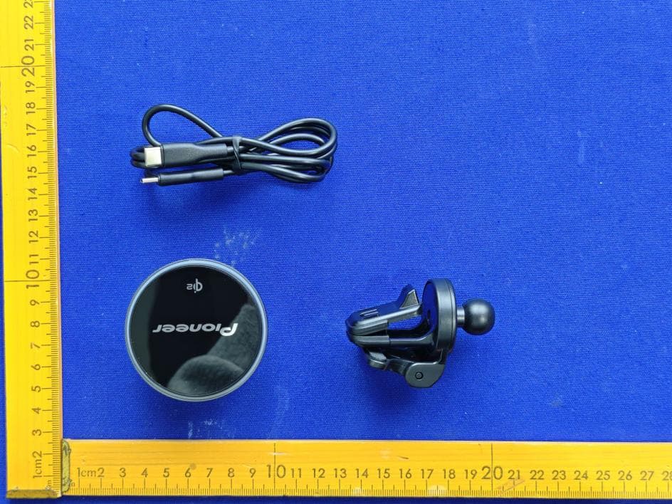
AJDK132
Jan 29, 2026WIRELESS CHARGING CRADLE
Equipment Class
DCD - Part 15 Low Power Transmitter Below 1705 kHz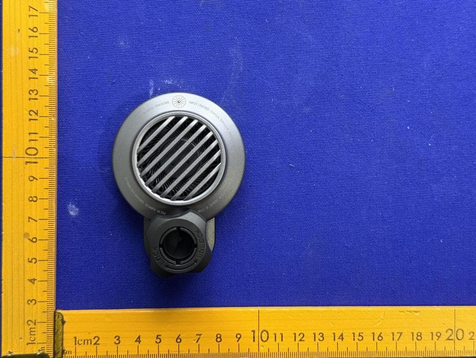
AJDK131
Jan 29, 2026WIRELESS CHARGING CRADLE
Equipment Class
DCD - Part 15 Low Power Transmitter Below 1705 kHzAJDK129
Nov 17, 2025RDS AV RECEIVER
Equipment Class
DSS - Part 15 Spread Spectrum Transmitter
AJDK122
Dec 11, 2022RDS AV RECEIVER
Equipment Class
NII - Unlicensed National Information Infrastructure TX