AJDK061Car Audio with Bluetooth
Pioneer Corporation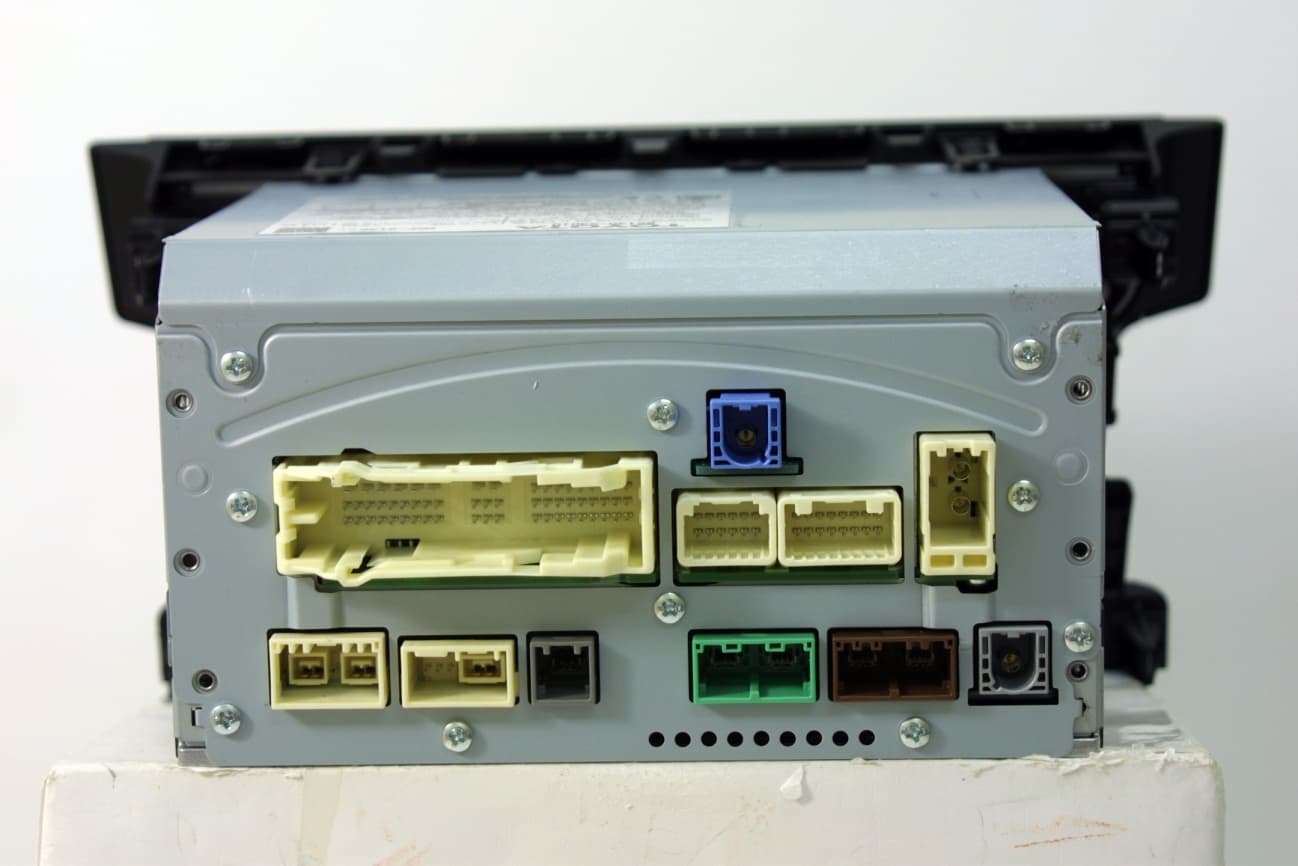
Click to zoom
Application Details
- Equipment Class
- DTS - Digital Transmission System
- Date of Grant
- Dec 10, 2012
- Application Purpose
- Original Equipment
- Date of Application
- Dec 10, 2012
- Equipment Note
- Car Audio with Bluetooth
- Frequency Range
- 2412.00000000 - 2462.00000000
- Company
- Pioneer Corporation
- Country
- Japan
Documents & Files
Document Text
Text extracted from the exhibit documents filed with the FCC. Open a document above to read the original.
Users Manual
6.2.User’s Manual Requirement of FCC/IC rules FCC/IC User's manual requirements that are required by FCC/IC rules are described on user's manual of the vehicle as followings; 『" NXF-9138 and NXF-9338 " are installed in motor vehicle. Therefore, we will not supply the user's manual. So, following FCC/IC user’s manual statement will be stated in user’s manual of the motor vehicle.』 ■FCC ID FCC ID:AJDK061 ■OET65 caution This equipment complies with FCC radiation exposure limits set forth for an uncontrolled environment and meets the FCC radio frequency (RF) Exposure Guidelines in Supplement C to OET65. This equipment should be installed and operated keeping the radiator at least 20cm or more away from person’s body (excluding extremities: hands, wrists, feet and ankles). ■Co-Location caution This transmitter must not be co-located or operated in conjunction with any other antenna or transmitter. ■Statement This device complies with part 15 of the FCC Rules. Operation is subject to the following two conditions: (1) This device may not cause harmful interference, and (2) this device must accept any interference received, including interference that may cause undesired ■FCC WARNING FCC WARNING Changes or modifications not expressly approved by the party responsible for compliance could void the user's authority to operate the equipment. ■IC IDIC:775E-K061 ■RSS-102 caution This equipment complies with IC radiation exposure limits set forth for an uncontrolled environment and meets RSS-102 of the IC radio frequency (RF) Exposure rules. This equipment should be installed and operated keeping the radiator at least 20cm or more away from person’s body (excluding extremities: hands, wrists, feet and ankles). Cet équipement est conforme aux limites d’exposition aux rayonnements énoncées pour un environnement non contrôlé et respecte les règles d’exposition aux fréquences radio électriques (RF) CNR-102 de l’IC. Cet équipement doit être installé et utilisé en gardant une distance de 20 cm ou plus entre le dispositif rayonnant et le corps (à l’exception des extrémités : mains, poignets, pieds et chevilles). ■Antenna caution Under Industry Canada regulations, this radio transmitter may only operate using an antenna of a type and maximum (or lesser) gain approved for the transmitter by Industry Canada. To reduce potential radio interference to other users, the antenna type and its gain should be so chosen that the equivalent isotropically radiated power (e.i.r.p.) is not more than that necessary for successful communication. Conformément à la réglementation d'Industrie Canada, le présent émetteur radio peut fonctionner avec une antenne d'un type et d'un gain maximal (ou inférieur) approuvé pour l'émetteur par Industrie Canada. Dans le but de réduire les risques de brouillage radioé lectrique à l'intention des autres utilisateurs, il faut choisir le type d'antenne et son gain de sorte que la puissance isotrope rayonnée équivalente (p.i.r.e.) ne dépasse pas l'intensité nécessaire à l'établissement d'une communication satisfaisante. ■Statement This device complies with Industry Canada licence-exempt RSS standard(s). Operation is subject to the following two conditions: (1) this device may not cause interference, and (2) this device must accept any interference, including interference that may cause undesired operation of the device. Le présent appareil est conforme aux CNR d'Industrie Canada applicables aux appareils radio exempts de licence. L'exploitation est autorisée aux deux conditions suivantes : (1) l'appareil ne doit pas produire de brouillage, et (2) l'utilisateur de l'appareil doit accepter tout brouillage radioélectrique subi, même si le brouillage est susceptible d'en compromettre le fonctionnement. FCC IC
External Photos
Pioneer Corporation Receiver Ass’y FCC ID:AJDK061 Model: NXF-9138 External Photo Front Rear Pioneer Corporation Receiver Ass’y FCC ID:AJDK061 Model: NXF-9138 External Photo To p Bottom Pioneer Corporation Receiver Ass’y FCC ID:AJDK061 Model: NXF-9138 External Photo Right Left
ID Label/Location Info
Label Position NXF-9138 NXF-9338
Internal Photos
Pioneer Corporation Receiver Ass’y FCC ID: AJDK061 IC Number:775E-K061 Internal Photo Side A with Shield Side A without Shield Pioneer Corporation Receiver Ass’y FCC ID: AJDK061 IC Number:775E-K061 Internal Photo Side B Bluetooth/WLAN Board Position Pioneer Corporation Receiver Ass’y FCC ID: AJDK061 IC Number:775E-K061 Internal Photo Antenna Antenna Position
RF Exposure Info
UL Japan, Inc. Shonan EMC Lab. 1-22-3 Megumigaoka, Hiratsuka-shi, Kanagawa-ken, 259-1220 JAPAN Telephone : +81 463 50 6400 Facsimile : +81 463 50 6401 Applicant: PIONEER CORPORATION T ype of Equipment : Car Audio with Bluetooth M odel No. : NXF-9338 FCC ID: AJDK061 PIO N EER C OR PO RATION declares that M odel : C ar Audio with Bluetooth complies with FCC radiation exposure requirement specified in the FCC Rules 2.1091. The “NXF-9338“ has 158.85 mW of conducted Peak O utput power and 251.76 mW of EIRP. This equipment is considered as a mobile device so that SAR testing is excluded. The Following calculation is the reference data for 20cm distance. RF Exposure Calculations: The following information provides the minimum separation distance for the highest gain antenna provided with the “NXF-9338“ as calculated from FCC OET Bulletin 65 Appendix A, Table (B) Limits for General Population / Uncontrolled Exposure. This calculation is based on the highest EIRP possible from the system, considering maximum power and antenna gain, and considering a 1.0mW/cm^2 uncontrolled exposure limit. The Friis formula used was: S = (P * G) / (4* π * r 2 ) Where P = 158.85 mW (M aximum peak output power) G = 1.58 Numerical Antenna gain; equal 2.00 dBi r =20.0 cm For: NXF-9338S = 0.05009mW/cm 2 No. : 32LE0328-SH-01-A RF Ex posure / SAR Statement
Test Report
Test report No. : 32LE0328-SH-01-A Page : 2 of 62 Issued date : November 15, 2012 Revised date : November 20, 2012 FCC ID : AJDK061 UL Japan, Inc. Shonan EMC Lab. 1-22-3 Megumigaoka, Hiratsuka-shi, Kanagawa-ken, 259-1220 JAPAN Telephone : +81 463 50 6400 Facsimile : +81 463 50 6401 REVISION HISTORY Original Test Report No.: 32LE0328-SH-01-A Revision Test report No. Date Page revised Contents - (Original) 32LE0328-SH-01-A November 15, 2012 - - 1 32LE0328-SH-01-A November 20, 2012 P1-2, 4-5, 17 P4: Correction of bandwidth for WLAN P5: Correction of supplied voltage P17: Correction of -6dB bandwidth Test report No. : 32LE0328-SH-01-A Page : 3 of 62 Issued date : November 15, 2012 FCC ID : AJDK061 UL Japan, Inc. Shonan EMC Lab. 1-22-3 Megumigaoka, Hiratsuka-shi, Kanagawa-ken, 259-1220 JAPAN Telephone : +81 463 50 6400 Facsimile : +81 463 50 6401 Contents Page SECTION 1: Customer information ..................................................................................... 4 SECTION 2: Equipment under test (E.U.T.) ....................................................................... 4 SECTION 3: Test specification, procedures & results ......................................................... 6 SECTION 4: Operation of E.U.T. during testing ................................................................. 8 SECTION 5: Out of band emissions (Antenna port conducted) ....................................... 11 SECTION 6: 6dB bandwidth & Occupied bandwidth (99%) ........................................... 11 SECTION 7: Maximum peak output power ...................................................................... 11 SECTION 8: Peak power density........................................................................................ 11 SECTION 9: Radiated emission ......................................................................................... 12 Contents of APPENDIXES ................................................................................................... 14 APPENDIX 1: Data of radio tests ....................................................................................... 15 APPENDIX 2: Test instruments ......................................................................................... 60 APPENDIX 3: Photographs of test setup ........................................................................... 62 Test report No. : 32LE0328-SH-01-A Page : 4 of 62 Issued date : November 15, 2012 Revised date : November 20, 2012 FCC ID : AJDK061 UL Japan, Inc. Shonan EMC Lab. 1-22-3 Megumigaoka, Hiratsuka-shi, Kanagawa-ken, 259-1220 JAPAN Telephone : +81 463 50 6400 Facsimile : +81 463 50 6401 SECTION 1: Customer information Company Name : PIONEER CORPORATION Brand name : Pioneer Address : 25-1 Aza-Nishi-machi, Yamada, Kawagoe-shi, Saitama, 350-8555, JAPAN Telephone Number : +81-49-228-6415 Facsimile Number : +81-49-228-6493 Contact Person : Makoto Kaieda SECTION 2: Equipment under test (E.U.T.) 2.1 Identification of E.U.T. Type of Equipment : Car Audio with Bluetooth Model No. : NXF-9338 Serial No. : See Section 4. Rating : DC 13.2V Country of Mass-production : Japan Condition of EUT : Engineering prototype (Not for Sale: This sample is equivalent to mass-produced items.) Modification of EUT : No modification by the test lab. Receipt Date of Sample : October 10, 2012 2.2 Product description Model: NXF-9338 (referred to as the EUT in this report) is a Car Audio with Bluetooth. The EUT has a derived model: NXF-9138 Difference is the audio amplifier and the design. Radio specification: Bluetooth: Equipment type : Transceiver Frequency of operation : 2402-2480MHz Bandwidth & channel spacing : 79MHz & 1MHz Type of modulation : GFSK, π/4DQPSK, 8DPSK Antenna type : Ceramic patch antenna Antenna gain with cable loss : +2dBi (max) Antenna connector type : MHF series micro coaxial connector receptacle vertical Operation temperature range : -20 to +65 deg.C. Refer to the test report: 32LE0328-SH-01-B for Bluetooth part. Wireless LAN: Equipment type : Transceiver Frequency of operation : 2412-2462MHz Bandwidth & channel spacing : 20MHz & 5MHz Type of modulation : BPSK, QPSK, CCK, 16QAM, 64QAM Antenna type : Ceramic patch antenna Antenna gain with cable loss : +2dBi (max) Antenna connector type : MHF series micro coaxial connector receptacle vertical Operation temperature range : 20 to +65 deg.C. Test report No. : 32LE0328-SH-01-A Page : 5 of 62 Issued date : November 15, 2012 Revised date : November 20, 2012 FCC ID : AJDK061 UL Japan, Inc. Shonan EMC Lab. 1-22-3 Megumigaoka, Hiratsuka-shi, Kanagawa-ken, 259-1220 JAPAN Telephone : +81 463 50 6400 Facsimile : +81 463 50 6401 FCC 15.31 (e) The equipment provides the wireless transmitter with stable power supply (DC3.3V). Therefore, the equipment complies with the requirement. FCC 15.203 The equipment and its antenna comply with this requirement since this antenna is built in the equipment and it cannot be replaced by end users. Clock Frequency: Item Reason For Use Frequency Navi Board NAVI SYSTEM CLOCK 32.4576MHz MIC AD (M3:12kHz) 12.288MHz PCIe (Oscillator) 100.01MHz SATA CLOCK 100.01MHz USB (Oscillator) 48MHz GPS CLOCK 16.368MHz MOST CLOCK 12.288MHz DOT CLOCK 33.231MHz NTSC CLOCK 27MHz GVIF CLOCK 24MHz DC-DC CONVERTER 416kHz DC-DC CONVERTER 463kHz REAL TIME CLOCK 32.768kHz RESET CPU CLOCK 4MHz Audio Board SYSTEM MICROCOMPUTER 16MHz MICROCOMPUTER COMMUNICATION 4MHz DC-DC CONVERTER 500kHz DC-DC CONVERTER 461kHz SUB MICROCOMPUTER 6MHz CAN MICROCOMPUTER 8MHz A/D CONVERTER 24.576MHz DVD MECH. 27MHz VIDEO_DAC 108MHz SDRAM 121.5MHz FM/AM TUNER 74.1MHz INTERMEDIATE FREQUENCY 10.7MHz XM FRONTEND 1871.004MHz XM FRONTEND 467.751MHz XM BACKEND 24.265MHz XM MICROCOMPUTER 4.7175MHz Panel Board PANEL MICROCOMPUTER 9.83MHz DC-DC CONVERTER 100kHz BLUETOOTH MODULE 26MHz BLUETOOTH DIGITAL AUDIO BIT CLOCK 2.086MHz Test report No. : 32LE0328-SH-01-A Page : 6 of 62 Issued date : November 15, 2012 FCC ID : AJDK061 UL Japan, Inc. Shonan EMC Lab. 1-22-3 Megumig…
Text truncated - open the document above for the full version.
Test Setup Photos
Test report No. : 32LE0328-SH-01-A Page : 62 of 62 UL Japan, Inc. Shonan EMC Lab. 1-22-3 Megumigaoka, Hiratsuka-shi, Kanagawa-ken, 259-1220 JAPAN Telephone : +81 463 50 6400 Facsimile : +81 463 50 6401 APPENDIX 3: Photographs of test setup Radiated emission Front view Rear view (below 1GHz) Rear view (above 1GHz) END OF REPORT
Contact Information
Applicant
Takashi Tsuzura(Manager)
Technical Contact
UL Japan, Inc.Toyokazu Imamura
[email protected]81-463-50-6400
1-22-3 Megumigaoka, Hiratsuka-shi · Kanagawa-ken · Japan
Test Firm
UL Japan, Inc. Shonan EMC EMC Lab.Tetsuya Hashimoto
Technical Specifications
| # | Rule Parts | Frequency Range | Power Output |
|---|---|---|---|
| 1 | 15C | 2.41 GHz - 2.46 GHz | 158.90 mW |
Other Applications from Pioneer Corporation
AJDK133
Jun 15, 2026On-Dash Multimedia Display
Equipment Class
NII - Unlicensed National Information Infrastructure TX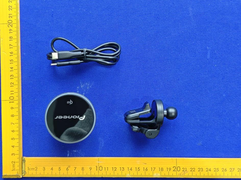
AJDK132
Jan 29, 2026WIRELESS CHARGING CRADLE
Equipment Class
DCD - Part 15 Low Power Transmitter Below 1705 kHz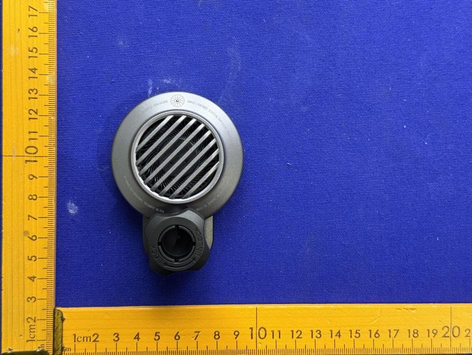
AJDK131
Jan 29, 2026WIRELESS CHARGING CRADLE
Equipment Class
DCD - Part 15 Low Power Transmitter Below 1705 kHzAJDK129
Nov 17, 2025RDS AV RECEIVER
Equipment Class
DSS - Part 15 Spread Spectrum Transmitter
AJDK122
Dec 11, 2022RDS AV RECEIVER
Equipment Class
NII - Unlicensed National Information Infrastructure TX