AJDT103Digital wireless speaker system transmitter
Pioneer Corporation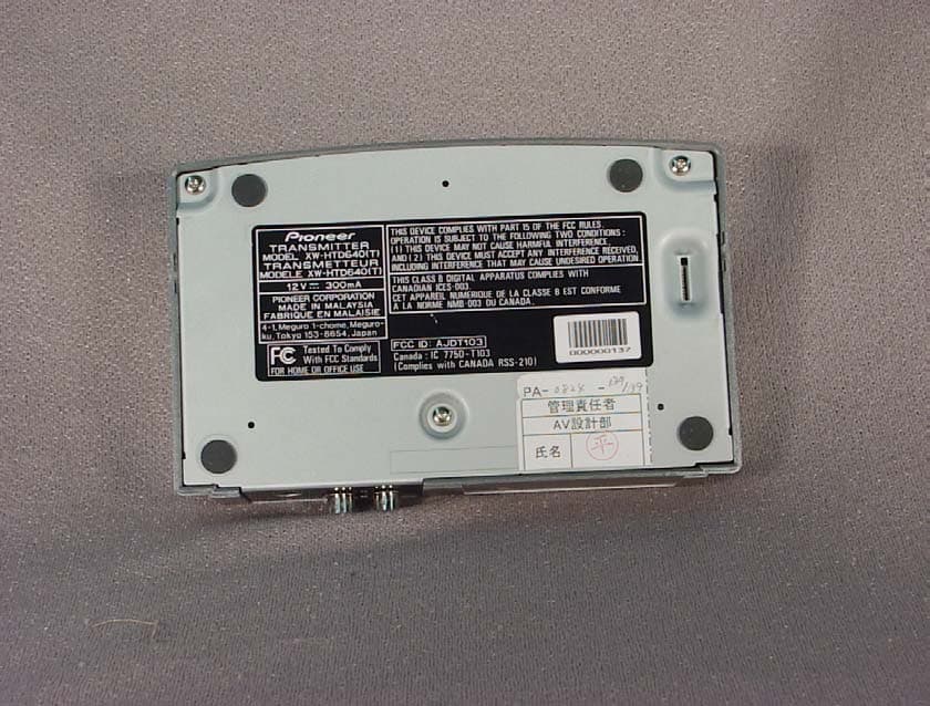
Click to zoom
Application Details
- Equipment Class
- DSS - Part 15 Spread Spectrum Transmitter
- Date of Grant
- May 24, 2004
- Application Purpose
- Original Equipment
- Date of Application
- May 24, 2004
- Equipment Note
- Digital wireless speaker system transmitter
- Frequency Range
- 2414.00000000 - 2468.00000000
- Company
- Pioneer Corporation
- Country
- Japan
Documents & Files
Document Text
Text extracted from the exhibit documents filed with the FCC. Open a document above to read the original.
Users Manual
Register your product at: www.pioneerelectronics.com • Protect your new investment The details of your purchase will be on file for reference in the event of an insurance claim such as loss or theft. • Improve product development Your input helps us continue to design products that meet your needs. • Receive a free Pioneer newsletter Registered customers can opt in to receive a monthly newsletter. • Receive free tips, updates and service bulletins on your new product HTD-645DV XV-HTD640/S-HTD540/XW-HTD640XV-HTD640/S-HTD630/XW-HTD630 HTD-641DV TUNED POWERWIRELESS MODE STEREO MODE VOLUME CHANNEL SURROUNDSTEREOMINMAXAUTO ON/OFF OFFON AUTO OFFON wireless Digital speaker system PHONES STANDBY/ON DOWN VOLUME CD MODE TIMER UP DVD/CDTUNERTV/L1/L2 FM/AM/ST. DIRECT PLAY DISC SKIPEXCHANGE OPEN/CLOSE 12345 DISC 12345 PHONES STANDBY/ON DOWN VOLUME CD MODE TIMER UP DVD/CDTUNERTV/L1/L2 FM/AM/ST. DIRECT PLAY DISC SKIPEXCHANGE OPEN/CLOSE 12345 DISC 12345 DVD/CD Receiver XV-HTD640 Speaker System S-HTD540 S-HTD630 Digital Wireless Speaker System XW-HTD640 XW-HTD630 Operating Instructions The exclamation point within an equilateral triangle is intended to alert the user to the presence of important operating and maintenance (servicing) instructions in the literature accompanying the appliance. The lightning flash with arrowhead, within an equilateral triangle, is intended to alert the user to the presence of uninsulated "dangerous voltage" within the product's enclosure that may be of sufficient magnitude to constitute a risk of electric shock to persons. CAUTION: TO PREVENT THE RISK OF ELECTRIC SHOCK, DO NOT REMOVE COVER (OR BACK). NO USER-SERVICEABLE PARTS INSIDE. REFER SERVICING TO QUALIFIED SERVICE PERSONNEL. CAUTION RISK OF ELECTRIC SHOCK DO NOT OPEN D1-4-2-3_En WARNING– TO PREVENT FIRE OR SHOCK HAZARD, DO NOT EXPOSE THIS APPLIANCE TO RAIN OR MOISTURE. D1-4-2-1_En IMPORTANT NOTICE– THE SERIAL NUMBER FOR THIS EQUIPMENT IS LOCATED IN THE REAR. PLEASE WRITE THIS SERIAL NUMBER ON YOUR ENCLOSED WARRANTY CARD AND KEEP IN A SECURE AREA. THIS IS FOR YOUR SECURITY. D1-4-2-6-1_En NOTE:This equipment has been tested and found to comply with the limits for a Class B digital device, pursuant to Part 15 of the FCC Rules. These limits are designed to provide reasonable protection against harmful interference in a residential installation. This equipment generates, uses, and can radiate radio frequency energy and, if not installed and used in accordance with the instructions, may cause harmful interference to radio communications. However, there is no guarantee that interference will not occur in a particular installation. If this equipment does cause harmful interference to radio or television reception, which can be determined by turning the equipment off and on, the user is encouraged to try to correct the interference by one or more of the following measures: – Reorient or relocate the receiving antenna. – Increase the separation between the equipment and receiver. – Connect the equipment into an outlet on a circuit different from that to which the receiver is connected. – Consult the dealer or an experienced radio/TV technician for help. D8-10-1-2_En For U.S. and Australia Model C67-7-3_En CAUTION– PREVENT ELECTRIC SHOCK DO NOT USE THIS (POLARIZED) PLUG WITH AN EXTENSION CORD. RECEPTACLE OR OTHER OUTLET UNLESS THE BLADES CAN BE FULLY INSERTED TO PREVENT BLADE EXPOSURE. ATTENTION– POUR PREVENIR LES CHOCS ELECTRIQUES NE PAS UTILISER CETTE FICHE POLARISEE AVEC UN PROLONGATEUR UNE PRISE DE COURANT OU UNE AUTRE SORTIE DE COURANT, SAUF SI LES LAMES PEUVENT ETRE INSEREES A FOND SANS EN LAISSER AUCUNE PARTIE A DECOUVVERT. D2-4-4-1_EF Energy-saving design This system is designed to use 0.5W of electricity when power is switched to standby. [Excluding XW-HTD630/640] [For Canadian model only] [Pour le modèle Canadien] READ INSTRUCTIONS— All the safety and operating instructions should be read before the product is operated. RETAIN INSTRUCTIONS— The safety and operating instructions should be retained for future reference. HEED WARNINGS — All warnings on the product and in the operating instructions should be adhered to. FOLLOW INSTRUCTIONS — All operating and use instructions should be followed. CLEANING— The product should be cleaned only with a polishing cloth or a soft dry cloth. Never clean with furniture wax, benzine, insecticides or other volatile liquids since they may corrode the cabinet. ATTACHMENTS — Do not use attachments not recommended by the product manufacturer as they may cause hazards. WATER AND MOISTURE — Do not use this product near water — for example, near a bathtub, wash bowl, kitchen sink, or laundry tub; in a wet basement; or near a swimming pool; and the like. ACCESSORIES— Do not place this product on an unstable cart, stand, tripod, bracket, or table. The product may fall, causing serious injury to a child or adult, and serious damage to the product. Use only with a cart, stand, tripod, bracket, or table recommended by the manufacturer, or sold with the product. Any mounting of the product should follow the manufacturer’s instructions, and should use a mounting accessory recommended by the manufacturer. CART — A product and cart combination should be moved with care. Quick stops, excessive force, and uneven surfaces may cause the product and cart combination to overturn. VENTILATION — Slots and openings in the cabinet are provided for ventilation and to ensure reliable operation of the product and to protect it from overheating, and these openings must not be blocked or covered. The openings should never be blocked by placing the product on a bed, sofa, rug, or other similar surface. This product should not be placed in a built-in installation such as a bookcase or rack unless proper ventilation is provided or the manufacturer’s instructions have been adhered to. POWER SOURCES — This product should be operated only from the type of power source indicated on the marking label. If you are not sure of…
Text truncated - open the document above for the full version.
External Photos
FCC ID: AJDT103 External Photo Pioneer Corporation Front Back FCC ID: AJDT103 External Photo Pioneer Corporation Top Bottom
ID Label/Location Info
XW-HTD640 LOCATION of Rating Label Label Material: Surface Material: Paper (LINTEC SK coat SP-3/White) Bonding Material: Adhesive
ID Label/Location Info
XW-HTD640 Rating Label Label Material: Surface Material: Paper (LINTEC SK coat SP-3/White) Bonding Material: Adhesive
Internal Photos
FCC ID: AJDT103 Internal Photo Pioneer Corporation Front side with shield Front side without shield FCC ID: AJDT103 Internal Photo Pioneer Corporation Back Side
RF Exposure Info
Applicant: Pioneer Corporation Type of Equipment : Digital W ireless Speaker System (Transmitter) M odel No. : X W -H TD640(T) FCC ID: AJDT103 RF Exposure Calculations: The following information provides the minimum separation distance for the highest gain antenna provided with the “XW -HTD640(T)“ as calculated from FCC OET Bulletin 65 Appendix A, Table (B) Limits for General Population / Uncontrolled Exposure. This calculation is based on the highest EIRP possible from the system, considering maximum power and antenna gain, and considering a 1.0mW /cm^2 uncontrolled exposure lim it. The Friis form ula used w as: S = (P * G) / (4* ƒÎ * r 2 ) W here P = 15.49 mW (Maximum peak output power) G = 1.11 Numerical Antenna gain; equal 0.44 dBi r =20.0 cm For: XW -HTD640(T) S = 0.00341 mW/cm 2 No. : 24GE0288-HO-1 RF Exposure / SAR Statement
Test Report
Test report No. : 24GE0288-HO-1 Page : 2 of 32 Issued date : April 5, 2004 FCC ID : AJDT103 UL Apex Co., Ltd. Head Office EMC Lab. 4383-326 Asama-cho, Ise-shi, Mie-ken 516-0021 JAPAN Telephone : +81 596 24 8116 Facsimile : +81 596 24 8124 MF060b(10.04.03) CONTENTS PAGE SECTION 1: Client information...........................................................................................................3 SECTION 2: Equipment under test (E.U.T.).........................................................................................3 SECTION 3: Test specification, procedures & results...........................................................................5 SECTION 4: Operation of E.U.T. during testing..................................................................................7 SECTION 5: Conducted Emission, Section 15.207................................................................................8 SECTION 6: 6dB Bandwidth, Section 15.247(a)(2)...............................................................................8 SECTION 7: Maximum Peak Output Power, Section 15.247(b)(3).......................................................8 SECTION 8: Out of Band Emission, Section 15.247 (c).........................................................................9 SECTION 9: Peak Power Density, Section 15.247 (d)...........................................................................9 APPENDIX 1: Photographs of test setup............................................................................................10 Conducted Emission..................................................................................................................10 Spurious Emission (Radiated)....................................................................................................11 APPENDIX 2: Test instruments..........................................................................................................12 APPENDIX 3: Data of EMI................................................................................................................13 Conducted emission...................................................................................................................13 6dB Bandwidth.........................................................................................................................16 Maximum Peak OutPut Power..................................................................................................18 Radiated Spurious Emission......................................................................................................20 Conducted Spurious Emission...................................................................................................26 Conducted emission Band Edge compliance...............................................................................29 Power Density...........................................................................................................................30 99%Occupied Bandwidth..........................................................................................................32 Test report No. : 24GE0288-HO-1 Page : 3 of 32 Issued date : April 5, 2004 FCC ID : AJDT103 UL Apex Co., Ltd. Head Office EMC Lab. 4383-326 Asama-cho, Ise-shi, Mie-ken 516-0021 JAPAN Telephone : +81 596 24 8116 Facsimile : +81 596 24 8124 MF060b(10.04.03) SECTION 1: Client information Company name : Pioneer Corporation Brand name : PIONEER Address : 4-2610 Hanazono, Tokorozawa-shi, Saitama, 359-8522, JAPAN Telephone Number : +81-42-990-2438 Facsimile Number : +81-42-990-2077 Contact Person : Tatsuo Ohnobu SECTION 2: Equipment under test (E.U.T.) 2.1 Identification of E.U.T. Type of Equipment : Digital Wireless Speaker System (Transmitter) Model No. : XW-HTD640(T) Serial No. : 000000137(Spurious emissions /Radiated) 000000135 (Other tests except for the Spurious emissions) Country of Manufacture : Malaysia Rating : AC Adaptor:AC120V/60Hz Receipt Date of Sample : March 15, 2004 Condition of EUT : Engineering prototype (Not for sale: This sample is equivalent to mass-produced items.) Test report No. : 24GE0288-HO-1 Page : 4 of 32 Issued date : April 5, 2004 FCC ID : AJDT103 UL Apex Co., Ltd. Head Office EMC Lab. 4383-326 Asama-cho, Ise-shi, Mie-ken 516-0021 JAPAN Telephone : +81 596 24 8116 Facsimile : +81 596 24 8124 MF060b(10.04.03) 2.2 Product Description Pioneer Corporation, Model No. XW-HTD640(T) is the Digital Wireless Speaker System (Transmitter) (Transmitter) Equipment Type : Transmitter Frequency band : from 2414 MHz to 2468 MHz Frequency of operation : 2414, 2432, 2450, 2468MHz Type of Modulation : GFSK Antenna Type : Dipole Antenna Gain : 0.44dBi ITU code : F1D Mode of operation : Simplex Other clock frequency : 8MHz and 24.576MHz. Method of Frequency Generation : Crystal (Receiver) Type of Receiver : Receiver Frequency band : from 2414 MHz to 2468 MHz Frequency of operation : 2414, 2432, 2450, 2468MHz Type of Modulation : GFSK Antenna Type : Dipole Antenna Gain : 0.44dBi ITU code : F1D Other clock frequency : 8 MHz, 12.288 MHz, and 24.576MHz Method of Frequency Generation : Crystal FCC 15.31 (e) This EUT provides stable voltage constantly to RF Module by the AC Adaptor. Therefore, this EUT complies with the requirement. FCC Part 15.203 Antenna requirement It is impossible for end users to replace the antenna, because the antenna is mounted inside of the EUT. Therefore, the equipment complies with the antenna requirement of Section 15.203. Test report No. : 24GE0288-HO-1 Page : 5 of 32 Issued date : April 5, 2004 FCC ID : AJDT103 UL Apex Co., Ltd. Head Office EMC Lab. 4383-326 Asama-cho, Ise-shi, Mie-ken 516-0021 JAPAN Telephone : +81 596 24 8116 Facsimile : +81 596 24 8124 MF060b(10.04.03) SECTION 3: Test specification, procedures & results 3.1 Test Specification Test Specification : FCC Part15 Subpart C : 2003 Title : FCC 47CFR Part15 Radio Frequency Device Subpart C Intentional Radiators Section 15.…
Text truncated - open the document above for the full version.
Test Setup Photos
Test report No. : 24GE0288-HO-1 Page : 10 of 32 Issued date : April 5, 2004 FCC ID : AJDT103 UL Apex Co., Ltd. Head Office EMC Lab. 4383-326 Asama-cho, Ise-shi, Mie-ken 516-0021 JAPAN Telephone : +81 596 24 8116 Facsimile : +81 596 24 8124 MF060b(10.04.03) APPENDIX 1: Photographs of test setup Conducted Emission Front Rear Test report No. : 24GE0288-HO-1 Page : 11 of 32 Issued date : April 5, 2004 FCC ID : AJDT103 UL Apex Co., Ltd. Head Office EMC Lab. 4383-326 Asama-cho, Ise-shi, Mie-ken 516-0021 JAPAN Telephone : +81 596 24 8116 Facsimile : +81 596 24 8124 MF060b(10.04.03) Spurious Emission (Radiated) Front Rear
Contact Information
Applicant
Takashi Tsuzura(Manager)
Technical Contact
UL Apex Co., Ltd.Hiroka Umeyama
[email protected]81-596-24-8116
4383-326 Asama-cho · Ise-shi, Mie-ken · Japan
Non-Technical Contact
UL Apex Co., LtdYoshiko Mizuta
[email protected]81-596-8116
Test Firm
UL Apex Co., Ltd.Tetsuya Hashimoto
Technical Specifications
| # | Rule Parts | Frequency Range | Power Output |
|---|---|---|---|
| 1 | 15C | 2.41 GHz - 2.47 GHz | 15.50 mW |
Other Applications from Pioneer Corporation
AJDK133
Jun 15, 2026On-Dash Multimedia Display
Equipment Class
NII - Unlicensed National Information Infrastructure TX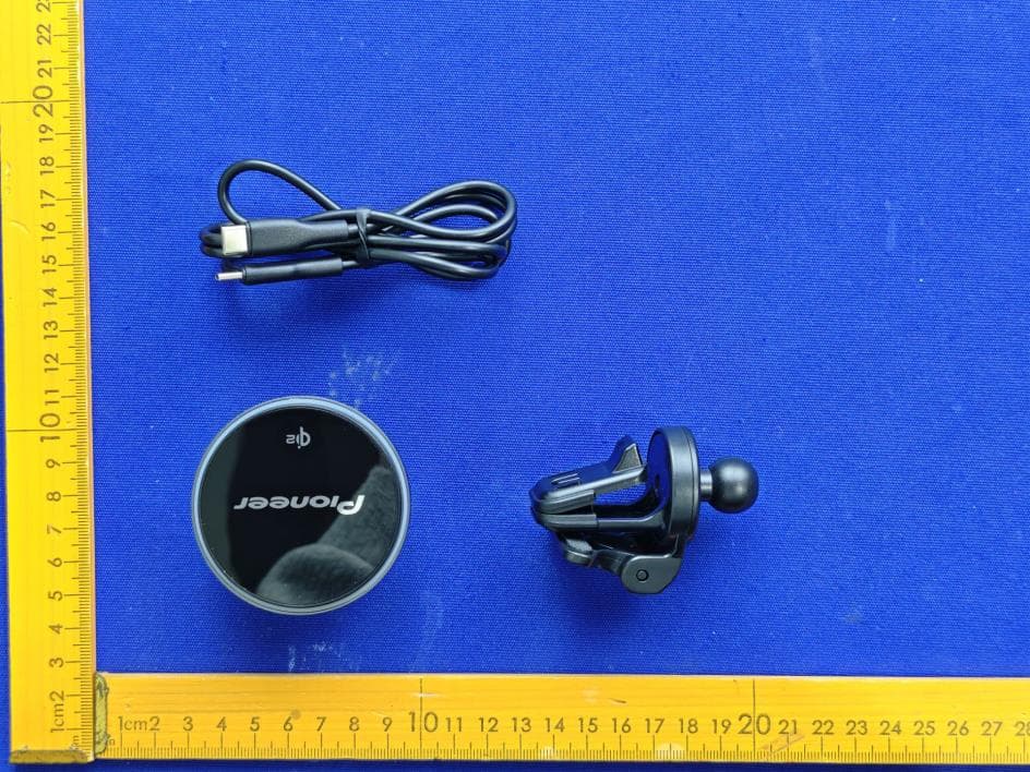
AJDK132
Jan 29, 2026WIRELESS CHARGING CRADLE
Equipment Class
DCD - Part 15 Low Power Transmitter Below 1705 kHz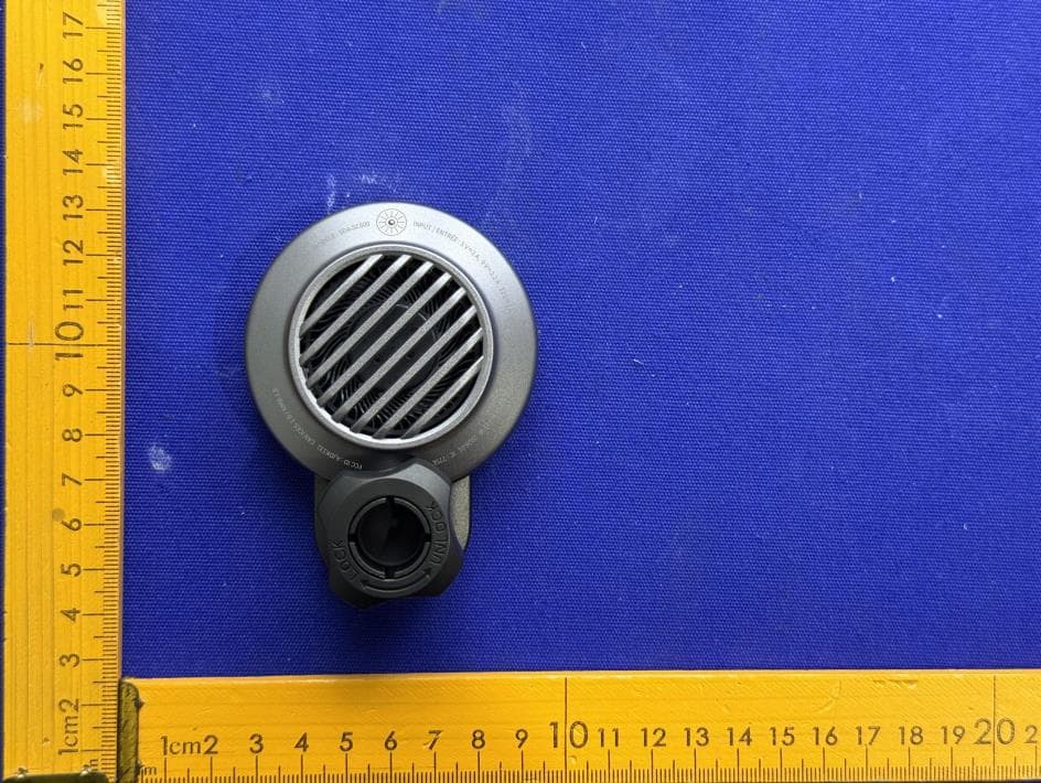
AJDK131
Jan 29, 2026WIRELESS CHARGING CRADLE
Equipment Class
DCD - Part 15 Low Power Transmitter Below 1705 kHzAJDK129
Nov 17, 2025RDS AV RECEIVER
Equipment Class
DSS - Part 15 Spread Spectrum Transmitter
AJDK122
Dec 11, 2022RDS AV RECEIVER
Equipment Class
NII - Unlicensed National Information Infrastructure TX