AJK6229210TRANSPONDER
Rockwell Collins Inc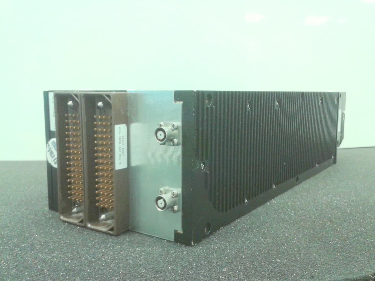
Click to zoom
Application Details
- Equipment Class
- TNB - Licensed Non-Broadcast Station Transmitter
- Date of Grant
- Dec 10, 2012
- Application Purpose
- Original Equipment
- Date of Application
- Dec 10, 2012
- Equipment Note
- TRANSPONDER
- Frequency Range
- 1090.00000000 - 1090.00000000
- Company
- Rockwell Collins Inc
- Country
- United States
Documents & Files
Document Text
Text extracted from the exhibit documents filed with the FCC. Open a document above to read the original.
Users Manual
component maintenance manual TDR-94/94D (-004 Status and Higher) ATC/Mode S Transponder (ICA) 34-50-96 (with illustrated parts list) Export Control Classification Notice (ECCN) for this document is 6E991. © Copyright 2010 Rockwell Collins, Inc. All rights reserved. May 20, 2010 TO: HOLDERS OF THE ROCKWELL COLLINS® TDR-94/94D (-004 STATUS AND HIGHER) ATC/MODE S TRANSPONDER (ICA) COMPONENT MAINTENANCE MANUAL WITH IPL (CPN 523-0778502) D ESCRIPTIONOFREVISIONNO13,MAY20,2010 This page shows all pages of the manual that are added, changed, or removed. Replace the specified pages of the manual with the new pages supplied. Record the applicable data on the Record of Revisions page. All changed pages keep data necessary to do maintenanceon all equipment models. Black bars on the side of the page identify changes. PAGE NUMBER DESCRIPTION OF REVISION AND REASON FOR CHANGE SERVICE BULLETIN EFFECTIVITY LEP-1 thru LEP-14 Updated to reflect current revision.NoneAll models LOI-3 thru LOI-5/LOI-6 Updated to reflect current revision.NoneAll models LOT-1, LOT-2 Updated to reflect current revision.NoneAll models INTRO-3Revised Note explaining the use of XXX.NoneAll models 2Revised Equipment Covered Table 1 to add new CPNs. None622-9352-310, 622-9352-410, 622-9210-310, 622-9210-410 23 thru 26, 28 Revised Assembly Identification Tables, Table 6 to include new CPNs. 622-9352-310, 622-9352-410, 622-9210-310, 622-9210-410 2007, 2009/ 2010 Revised Assembly Revision Level and Diagram Reference Table 2002 to add new cards. All models 2008Relocation of data.NoneAll models 2048.1/2048.2 Added Power Amplifier Circuit Card A2 (CPN 687-0722-006), Maintenance Aid and Schematic Changes Table 2006.1. NoneAll models 1 PAGE NUMBER DESCRIPTION OF REVISION AND REASON FOR CHANGE SERVICE BULLETIN EFFECTIVITY 2048.3/2048.4 thru 2048.7/ 2048.8 Added Power Amplifier Circuit Card A2 (CPN 687-0722-006), Maintenance Aid Diagram Figure 2008.1. NoneAll models 2048.9/2048.10 thru 2048.13/ 2048.14 Added Power Amplifier Circuit Card A2 (CPN 687-0722-006), Schematic Diagram Figure 2008.2. NoneAll models 2146.1/2146.2 Added CPU-I/O Programmed Assembly A5 (CPN 653-3674-025, -026) and CPU-I/O Circuit Card A5A1 (CPN 828-2700-004), Maintenance Aid and Schematic Changes Table 2012.1. NoneAll models 2146.3/2146.4 thru 2146.9/ 2146.10 Added CPU-I/O Programmed Assembly A5 (CPN 653-3674-025, -026) and CPU-I/O Circuit Card A5A1 (CPN 828-2700-004), Maintenance Aid Diagram Figure 2021.1. NoneAll models 2146.11/ 2146.12 thru 2146.27/ 2146.28 Added CPU-I/O Programmed Assembly A5 (CPN 653-3674-025, -026) and CPU-I/O Circuit Card A5A1 (CPN 828-2700-004), Schematic Diagram Figure 2021.2 . NoneAll models 2195/2196Revised Video Processor Circuit Card A6 (CPN 687-0726-006) and Video Processor Circuit Card Assembly A6 (CPN 983-8019-001), Maintenance Aid and Schematic Changes Table 2015. NoneAll models 2220.1/2220.2 Added Video Processor Circuit Card A6 (CPN 687-0726-007), Maintenance Aid and Schematic Changes Table 2015.1. NoneAll models 2220.3/2220.4 thru 2220.9/ 2220.10 Added Video Processor Circuit Card A6 (CPN 687-0726-007), Maintenance Aid Diagram Figure 2028.1. NoneAll models 2220.11/ 2220.12 thru 2220.25/ 2220.26 Added Video Processor Circuit Card A6 (CPN 687-0726-007), Schematic Diagram Figure 2028.2. NoneAll models 2 PAGE NUMBER DESCRIPTION OF REVISION AND REASON FOR CHANGE SERVICE BULLETIN EFFECTIVITY 2239/2240Revised IF Receiver, DPSK Detector, and LVPS Circuit Card A7(CPN 687-0727-005), Maintenance Aid and Schematic Changes Table 2017. NoneAll models 2259/2260, 2261/2262 Revised IF Receiver, DPSK Detector, and LVPS Circuit Card A7(CPN 687-0727-005), Schematic Diagram (Sheets 6 and 7). NoneAll models 9005Revised Special Test Equipment Required. (Preferred List) Table 9002. NoneAll models 10004 thru 10005/10006 Updated Equipment Designator Prefixes table to reflect current revision and addition of top levels CPN 622-9210-310, -410, CPN 622-9352-310, -410; addition of Chassis Assembly, Main CPN 653-2254-039, -040, -041, -042 and addition of new figures 20 thru 24 CPN 687-0726-007, CPN 828-2700-004, CPN 687-0722-006, CPN 653-0030-002 and CPN 653-0030-003. NoneAll models 10007 thru 10011/10012 Updated Manufacturer's Code, Name and Address Index to reflect current revision. NoneAll models 10008.1/ 10008.2 New pages added to Manufacturer's Code, Name and Address Index due to new/revised data added on previous pages (data pushed from previous page). NoneAll models 10014 thru 10016, 10023 thru 10040, 10050 Updated Equipment Designator Index to reflect current revision. NoneAll models 3 PAGE NUMBER DESCRIPTION OF REVISION AND REASON FOR CHANGE SERVICE BULLETIN EFFECTIVITY 10014.1/ 10014.2, 10024.1/ 10024.2, 10026.1/ 10026.2, 10028.1/ 10028.2, 10032.1/ 10032.2, 10034.1/ 10034.2, 10036.1/ 10036.2, 10038.2/ 10038.2 New pages added to Equipment Designator Index due to new/revised data added on previous pages (datapushed from previous page). These pages also updated to reflect current revision. NoneAll models 10016.1/ 10016.2, 10040.1/ 10040.2 New pages added to Equipment Designator Index due to new/revised data added on previous pages (datapushed from previous page). NoneAll models 10051 thru 10083/10084 Updated Numerical Index to reflect current revision. NoneAll models 4 PAGE NUMBER DESCRIPTION OF REVISION AND REASON FOR CHANGE SERVICE BULLETIN EFFECTIVITY 10052.1/ 10052.2, 10054.1/ 10054.2, 10056.1/ 10056.2, 10058.1/ 10058.2, 10060.1/ 10060.2, 10062.1/ 10062.2, 10064.1/ 10064.2, 10068.1/ 10068.2, 10074.1/ 10074.2, 10076.1/ 10076.2, 10078.1/ 10078.2, 10080.1/ 10080.2, 10082.1/ 10082.2 New pages added to Numerical Index due to new/revised data added on previous pages (data pushed from previous page). These pages also updated to reflect current revision. NoneAll models 10085 thru 10090, 10091 thru 10101/ 10102 Updated Optional Vendor Index to reflect current revision. NoneAll models 10103/10104 Updated Figure 1 illustration and illustration title to reflect curren…
Text truncated - open the document above for the full version.
Users Manual
ROCKWELL COLLINS COMPONENT MAINTENANCE MANUAL with IPL TDR-94, PART NO 622-9352 STEPPROCEDUREDESIRED RESULTS 1.21Verify that no fault codes are indicated on the monitor in either the "F3" CSDB output word or in the "350" ARINC-429 Maintenance Data Output word. 1.22If the UUT fails the Mode-S_Only reply rate as specified in Table 1001/Table 34-50-96-99A-009-A01 step 1.1.A at ambient or during temperature test, first verify the DPSK alignment. If alignment is satisfactory but UUT still fails Table 1001/Table 34-50-96-99A-009-A01 step 1.1.A, replace A7R430 with another value from the test select listing as shown in the associated parts list. Reverify DPSK alignment and complete temperature testing as required. 1.23After alignment is complete, remove all power from test equipment and reassemble unit under test. 2.0Receiver IF/LVPS Assembly, Alignment for CPN 687-0727-005 or subsequent. 2.1Monitor the 5 VDC output (J7-26) with a DVM while adjusting A7R507 on the IF/Power Supply board. 5 VDC output adjusted to 4.99 to 5.01 Vdc. 2.2Monitor J7-33 on the Video Processor board with an oscilloscope. 2.3Set the MODE-S Test Set to generate ATCRBS MODE-C interrogations and apply to the bottom antenna connector. Set the interrogation rate to 450/second. 2.4a. Set the MODE-S Test Set signal strength for -79 dBm. b. Adjust A7R196 to the fully clock-wise position. Monitor the Bottom Video signal at pin 33 of A6P22 with an oscilloscope while adjusting A7R95. N OTE:Theoscilloscopemustbesettotheaveraging mode to properly measure the video pulse at the low signal levels required. An observed video level of 0.7 volts Peak. c. Set the MODE-S test set signal strength to -77 dBm. d. Monitor the Bottom Video signal at pin 33 of A6P22 while adjusting A7R196. An observed video level of 0.7 volts Peak. e. Verify that the reply rate is between 90% and 100%. If necessary, readjust A7R195 to the get the desired result. A reply rate between 90% and 100%. 2.5a. Set the MODE-S Test Set signal strength for -31 dBm. b. Monitor the P1 pulse at J7-33 with a DVM whiling adjusting A7R179 on the IF-Receiver. The P1 pulse adjusted to 4.99 to 5.01 V dc. Alignment Procedure Cont. Table 1002/Table 34-50-96-99A-010-A01 34-50-96 Page 1077 Apr 17/07 ROCKWELL COLLINS COMPONENT MAINTENANCE MANUAL with IPL TDR-94, PART NO 622-9352 STEPPROCEDUREDESIRED RESULTS 2.6Repeat steps 2.4 and 2.5 as necessary. 2.7a. Set the MODE-S Test Set signal strength for -27 dBm. b. Adjust A6R118 on the Video Processor board while monitoring the positive end of A6C67 with the oscilloscope. The observed ditch-slope waveformresultingfromP1is 16.2±.2μswideatitsbase. 2.8Steps 2.9 through 2.14 are applicable only to the TDR-94Ds that use the 687-0727-005 Receiver-IF/LVPS. MODE-C interrogations are applied only to the UUT top antenna port for these steps. 2.9a. Set the MODE-S Test Set signal strength for -79 dBm. b. Adjust A7R195 to the fully clockwise position. c. Monitor the Top Video signal at pin 31 of A6P22 with the oscilloscope with adjusting A7R94. N OTE:Theoscilloscopemustbesettotheaveraging mode to properly measure the video pulse at the low signal levels required. An observed video level of 0.7 volts Peak. d. Set the MODE-S Test Set signal strength for -77 dBm. e. Monitor the Top Video signal at pin 31 of A6P22 while adjusting A7R195 An observed video level of 0.7 volts Peak. 2.10Verify that the reply rate is between 90% and 100%. If necessary, readjust A7R94 to the get the desired result. A reply rate between 90% and 100%. 2.11a. Set the MODE-S Test Set signal strength for -31 dBm. b. Monitor the P1 pulse at J7-31 with a DVM whiling adjusting A7R178 on the IF-Receiver. The P1 pulse adjusted to 4.99 to 5.01 V dc. 2.12Repeat steps 2.10 and 2.11 as necessary. 2.13a. Set the MODE-S Test Set signal strength for -50 dBm. b. Measure and record the amplitude or the P1 pulse at J7-31.______ V c. Apply the same input signal level to the bottom channel. d. Measure and record the amplitude or the P1 pulse at J7-33.______ V Alignment Procedure Cont. Table 1002/Table 34-50-96-99A-010-A01 34-50-96 Page 1078 May 18/06 ROCKWELL COLLINS COMPONENT MAINTENANCE MANUAL with IPL TDR-94, PART NO 622-9352 STEPPROCEDUREDESIRED RESULTS 2.13 (cont) e. Verify that the two recorded amplitudes are with .1 V of each other. If necessary, readjust the higher voltage downward with A7R178 or A7R179 (whichever is applicable) until the two voltages are with .1 V of each other. N OTE:If readjustment of A7R178 or A7R179 was necessary, then the MTL for the top or bottom channel must also be readjusted in accordance with step 2.4 or 2.10 (whichever is appropriate). The difference between the two recorded voltages is 0 ± 0.1 V. 2.14a. Set the MODE-S Test Set signal strength for -27 dBm. b. Adjust A6R117 on the Video Processor board while monitoring the positive end of A6C59 with the oscilloscope. The observed ditch-slope waveform resulting from P1 is 16.2±.2μswideatitsbase. 2.15 N OTE:Use extreme care while making the adjustments in steps 2.15 through 2.17. Make the DPSK trimmer capacitor adjustments in very small increments. These adjustments are critical to the performance of the TDR-94/94D. a. To align the DPSK Demodulator VCO, interrogate the bottom channel with MODE-S ONLY ALL-CALL interrogations having a signal strength of -50 dBm. b. Adjust the interrogation center frequency above 1030 MHz until the reply rate decreases to 90%. Record this frequency as the upper limit. Upper Frequency limit: ____ MHz c. Adjust the interrogation center frequency below 1030 MHz until the reply rate decreases to 90%. Record this center frequency as the lower frequency limit . Lower Frequency limit: ____ MHz d. Adjust A7R223 to a level where the upper and lower frequency limits are equidistant from the 1030 MHz center frequency. The upper frequency limit must not be less than 1030.6 MHz and the lower frequency limit must not be greater than 1029.4 MHz 2.16a. To align the DPSK 60 MHz BPF interrogate the bottom ch…
Text truncated - open the document above for the full version.
Users Manual
ROCKWELL COLLINS COMPONENT MAINTENANCE MANUAL with IPL TDR-94, PART NO 622-9352 Synthesizer Circuit Card A4 (CPN 687-0724-003), Schematic Diagram Figure 2016 (Sheet 2 of 2)/GRAPHIC 34-50-96-99B-051-A01 34-50-96 Page 2089/2090 May 18/06 ROCKWELL COLLINS COMPONENT MAINTENANCE MANUAL with IPL TDR-94, PART NO 622-9352 MAINTENANCE AID/SCHEMATIC CHANGES REVISION IDENT (SHEET) DESCRIPTION OF REVISION AND CAUSE FOR CHANGE SERVICE BULLETIN EFFECTIVITY MARKING NOTE:Unless otherwise specified, all effectivity markings (REV A, REV B, etc.) in this figure, are for CPU-I/O Circuit Card A5A1 (CPN 828-2700-002). N/AReleased to production.REV A N/AProduction process change.REV B N/ACorrected part numbers for U21, U22, U32, and U33.REV C N/ADeleted Y contacts from J4-13 and J4-14 to correct a top channel temperature problem. REV D N/AAdded altered item drawing (AID) numbers for U13 and U16.REV E N/AChanged part number of electrical contact (symbol W). New contacts improve the production process; old contacts would not stay in place for soldering process. REV F N/AChanged U20 to type 80C196KC; old type 80C196 was no longer procurable. REV G N/AAdded CPU-I/O Programmed Assembly A5 (CPN 653-3674-003 and -004). 13Effectivity is marked on TDR-94/94D top level assembly. H (6)EEPROMs U24 and U25, 2816, are no longer procurable and are replaced by 28HC256 devices. REV H J (6)Grounded unused address inputs of U24 and U25 EEPROMS, to prevent NOVRAM failure. REV J K (9)Replaced ASIC U12, 8005-4062 with 31015. The 8005-4062 device is no longer procurable. REV K N/AReplaced U13 EEPROM 831-4505-001 with 831-4505-002. This software change incorporates elementary/enhanced surveillance. 501REV L M (8)Added 10Kവresistor R15 to U16-6.REV M CPU-I/O Programmed Assembly A5 (CPN 653-3674-001 thru -018) and CPU-I/O Circuit Card A5A1 (CPN 828-2700-002), Maintenance Aid and Schematic Changes Table 2011/Table 34-50-96-99A-022-A01 34-50-96 Page 2091 May 18/06 ROCKWELL COLLINS COMPONENT MAINTENANCE MANUAL with IPL TDR-94, PART NO 622-9352 CPU-I/O Programmed Assembly A5 (CPN 653-3674-001 thru -018), Maintenance Aid Diagram Figure 2017/GRAPHIC 34-50-96-99B-052-A01 34-50-96 Page 2092 May 18/06 ROCKWELL COLLINS COMPONENT MAINTENANCE MANUAL with IPL TDR-94, PART NO 622-9352 CPU-I/O Circuit Card A5A1 (CPN 828-2700-002), Maintenance Aid Diagram Figure 2018 (Sheet 1 of 4)/GRAPHIC 34-50-96-99B-053-A01 34-50-96 Page 2093/2094 May 18/06 ROCKWELL COLLINS COMPONENT MAINTENANCE MANUAL with IPL TDR-94, PART NO 622-9352 CPU-I/O Circuit Card A5A1 (CPN 828-2700-002), Maintenance Aid Diagram Figure 2018 (Sheet 2 of 4)/GRAPHIC 34-50-96-99B-053-A01 34-50-96 Page 2095/2096 May 18/06 ROCKWELL COLLINS COMPONENT MAINTENANCE MANUAL with IPL TDR-94, PART NO 622-9352 CPU-I/O Circuit Card A5A1 (CPN 828-2700-002), Maintenance Aid Diagram Figure 2018 (Sheet 3 of 4)/GRAPHIC 34-50-96-99B-053-A01 34-50-96 Page 2097/2098 May 18/06 ROCKWELL COLLINS COMPONENT MAINTENANCE MANUAL with IPL TDR-94, PART NO 622-9352 CPU-I/O Circuit Card A5A1 (CPN 828-2700-002), Maintenance Aid Diagram Figure 2018 (Sheet 4 of 4)/GRAPHIC 34-50-96-99B-053-A01 34-50-96 Page 2099/2100 May 18/06 ROCKWELL COLLINS COMPONENT MAINTENANCE MANUAL with IPL TDR-94, PART NO 622-9352 CPU-I/O Programmed Assembly A5 (CPN 653-3674-001 thru -018) and CPU-I/O Circuit Card A5A1 (CPN 828-2700-002), Schematic Diagram Figure 2019 (Sheet 1 of 9)/GRAPHIC 34-50-96-99B-054-A01 34-50-96 Page 2101/2102 May 18/06 ROCKWELL COLLINS COMPONENT MAINTENANCE MANUAL with IPL TDR-94, PART NO 622-9352 CPU-I/O Programmed Assembly A5 (CPN 653-3674-001 thru -018) and CPU-I/O Circuit Card A5A1 (CPN 828-2700-002), Schematic Diagram Figure 2019 (Sheet 2 of 9)/GRAPHIC 34-50-96-99B-054-A01 34-50-96 Page 2103/2104 May 18/06 ROCKWELL COLLINS COMPONENT MAINTENANCE MANUAL with IPL TDR-94, PART NO 622-9352 CPU-I/O Programmed Assembly A5 (CPN 653-3674-001 thru -018) and CPU-I/O Circuit Card A5A1 (CPN 828-2700-002), Schematic Diagram Figure 2019 (Sheet 3 of 9)/GRAPHIC 34-50-96-99B-054-A01 34-50-96 Page 2105/2106 May 18/06 ROCKWELL COLLINS COMPONENT MAINTENANCE MANUAL with IPL TDR-94, PART NO 622-9352 CPU-I/O Programmed Assembly A5 (CPN 653-3674-001 thru -018) and CPU-I/O Circuit Card A5A1 (CPN 828-2700-002), Schematic Diagram Figure 2019 (Sheet 4 of 9)/GRAPHIC 34-50-96-99B-054-A01 34-50-96 Page 2107/2108 May 18/06 ROCKWELL COLLINS COMPONENT MAINTENANCE MANUAL with IPL TDR-94, PART NO 622-9352 CPU-I/O Programmed Assembly A5 (CPN 653-3674-001 thru -018) and CPU-I/O Circuit Card A5A1 (CPN 828-2700-002), Schematic Diagram Figure 2019 (Sheet 5 of 9)/GRAPHIC 34-50-96-99B-054-A01 34-50-96 Page 2109/2110 May 18/06 ROCKWELL COLLINS COMPONENT MAINTENANCE MANUAL with IPL TDR-94, PART NO 622-9352 CPU-I/O Programmed Assembly A5 (CPN 653-3674-001 thru -018) and CPU-I/O Circuit Card A5A1 (CPN 828-2700-002), Schematic Diagram Figure 2019 (Sheet 6 of 9)/GRAPHIC 34-50-96-99B-054-A01 34-50-96 Page 2111/2112 May 18/06 ROCKWELL COLLINS COMPONENT MAINTENANCE MANUAL with IPL TDR-94, PART NO 622-9352 CPU-I/O Programmed Assembly A5 (CPN 653-3674-001 thru -018) and CPU-I/O Circuit Card A5A1 (CPN 828-2700-002), Schematic Diagram Figure 2019 (Sheet 7 of 9)/GRAPHIC 34-50-96-99B-054-A01 34-50-96 Page 2113/2114 May 18/06 ROCKWELL COLLINS COMPONENT MAINTENANCE MANUAL with IPL TDR-94, PART NO 622-9352 CPU-I/O Programmed Assembly A5 (CPN 653-3674-001 thru -018) and CPU-I/O Circuit Card A5A1 (CPN 828-2700-002), Schematic Diagram Figure 2019 (Sheet 8 of 9)/GRAPHIC 34-50-96-99B-054-A01 34-50-96 Page 2115/2116 May 18/06 ROCKWELL COLLINS COMPONENT MAINTENANCE MANUAL with IPL TDR-94, PART NO 622-9352 CPU-I/O Programmed Assembly A5 (CPN 653-3674-001 thru -018) and CPU-I/O Circuit Card A5A1 (CPN 828-2700-002), Schematic Diagram Figure 2019 (Sheet 9 of 9)/GRAPHIC 34-50-96-99B-054-A01 34-50-96 Page 2117/2118 May 18/06 ROCKWELL COLLINS COMPONENT MAINTENANCE MANUAL with IPL TDR-94, PART NO 622-9352 MAINTENANCE AID/SCHEMATIC CHANGES REVISION IDENT (SHEET) DESCRIPTION OF REVISION AND CAUSE FOR …
Text truncated - open the document above for the full version.
Users Manual
ROCKWELL COLLINS COMPONENT MAINTENANCE MANUAL with IPL TDR-94, PART NO 622-9352 Synthesizer Circuit Card A4 (CPN 687-0724-003), Schematic Diagram Figure 2016 (Sheet 2 of 2)/GRAPHIC 34-50-96-99B-051-A01 34-50-96 Page 2089/2090 May 18/06 ROCKWELL COLLINS COMPONENT MAINTENANCE MANUAL with IPL TDR-94, PART NO 622-9352 MAINTENANCE AID/SCHEMATIC CHANGES REVISION IDENT (SHEET) DESCRIPTION OF REVISION AND CAUSE FOR CHANGE SERVICE BULLETIN EFFECTIVITY MARKING NOTE:Unless otherwise specified, all effectivity markings (REV A, REV B, etc.) in this figure, are for CPU-I/O Circuit Card A5A1 (CPN 828-2700-002). N/AReleased to production.REV A N/AProduction process change.REV B N/ACorrected part numbers for U21, U22, U32, and U33.REV C N/ADeleted Y contacts from J4-13 and J4-14 to correct a top channel temperature problem. REV D N/AAdded altered item drawing (AID) numbers for U13 and U16.REV E N/AChanged part number of electrical contact (symbol W). New contacts improve the production process; old contacts would not stay in place for soldering process. REV F N/AChanged U20 to type 80C196KC; old type 80C196 was no longer procurable. REV G N/AAdded CPU-I/O Programmed Assembly A5 (CPN 653-3674-003 and -004). 13Effectivity is marked on TDR-94/94D top level assembly. H (6)EEPROMs U24 and U25, 2816, are no longer procurable and are replaced by 28HC256 devices. REV H J (6)Grounded unused address inputs of U24 and U25 EEPROMS, to prevent NOVRAM failure. REV J K (9)Replaced ASIC U12, 8005-4062 with 31015. The 8005-4062 device is no longer procurable. REV K N/AReplaced U13 EEPROM 831-4505-001 with 831-4505-002. This software change incorporates elementary/enhanced surveillance. 501REV L M (8)Added 10Kവresistor R15 to U16-6.REV M CPU-I/O Programmed Assembly A5 (CPN 653-3674-001 thru -018) and CPU-I/O Circuit Card A5A1 (CPN 828-2700-002), Maintenance Aid and Schematic Changes Table 2011/Table 34-50-96-99A-022-A01 34-50-96 Page 2091 May 18/06 ROCKWELL COLLINS COMPONENT MAINTENANCE MANUAL with IPL TDR-94, PART NO 622-9352 CPU-I/O Programmed Assembly A5 (CPN 653-3674-001 thru -018), Maintenance Aid Diagram Figure 2017/GRAPHIC 34-50-96-99B-052-A01 34-50-96 Page 2092 May 18/06 ROCKWELL COLLINS COMPONENT MAINTENANCE MANUAL with IPL TDR-94, PART NO 622-9352 CPU-I/O Circuit Card A5A1 (CPN 828-2700-002), Maintenance Aid Diagram Figure 2018 (Sheet 1 of 4)/GRAPHIC 34-50-96-99B-053-A01 34-50-96 Page 2093/2094 May 18/06 ROCKWELL COLLINS COMPONENT MAINTENANCE MANUAL with IPL TDR-94, PART NO 622-9352 CPU-I/O Circuit Card A5A1 (CPN 828-2700-002), Maintenance Aid Diagram Figure 2018 (Sheet 2 of 4)/GRAPHIC 34-50-96-99B-053-A01 34-50-96 Page 2095/2096 May 18/06 ROCKWELL COLLINS COMPONENT MAINTENANCE MANUAL with IPL TDR-94, PART NO 622-9352 CPU-I/O Circuit Card A5A1 (CPN 828-2700-002), Maintenance Aid Diagram Figure 2018 (Sheet 3 of 4)/GRAPHIC 34-50-96-99B-053-A01 34-50-96 Page 2097/2098 May 18/06 ROCKWELL COLLINS COMPONENT MAINTENANCE MANUAL with IPL TDR-94, PART NO 622-9352 CPU-I/O Circuit Card A5A1 (CPN 828-2700-002), Maintenance Aid Diagram Figure 2018 (Sheet 4 of 4)/GRAPHIC 34-50-96-99B-053-A01 34-50-96 Page 2099/2100 May 18/06 ROCKWELL COLLINS COMPONENT MAINTENANCE MANUAL with IPL TDR-94, PART NO 622-9352 CPU-I/O Programmed Assembly A5 (CPN 653-3674-001 thru -018) and CPU-I/O Circuit Card A5A1 (CPN 828-2700-002), Schematic Diagram Figure 2019 (Sheet 1 of 9)/GRAPHIC 34-50-96-99B-054-A01 34-50-96 Page 2101/2102 May 18/06 ROCKWELL COLLINS COMPONENT MAINTENANCE MANUAL with IPL TDR-94, PART NO 622-9352 CPU-I/O Programmed Assembly A5 (CPN 653-3674-001 thru -018) and CPU-I/O Circuit Card A5A1 (CPN 828-2700-002), Schematic Diagram Figure 2019 (Sheet 2 of 9)/GRAPHIC 34-50-96-99B-054-A01 34-50-96 Page 2103/2104 May 18/06 ROCKWELL COLLINS COMPONENT MAINTENANCE MANUAL with IPL TDR-94, PART NO 622-9352 CPU-I/O Programmed Assembly A5 (CPN 653-3674-001 thru -018) and CPU-I/O Circuit Card A5A1 (CPN 828-2700-002), Schematic Diagram Figure 2019 (Sheet 3 of 9)/GRAPHIC 34-50-96-99B-054-A01 34-50-96 Page 2105/2106 May 18/06 ROCKWELL COLLINS COMPONENT MAINTENANCE MANUAL with IPL TDR-94, PART NO 622-9352 CPU-I/O Programmed Assembly A5 (CPN 653-3674-001 thru -018) and CPU-I/O Circuit Card A5A1 (CPN 828-2700-002), Schematic Diagram Figure 2019 (Sheet 4 of 9)/GRAPHIC 34-50-96-99B-054-A01 34-50-96 Page 2107/2108 May 18/06 ROCKWELL COLLINS COMPONENT MAINTENANCE MANUAL with IPL TDR-94, PART NO 622-9352 CPU-I/O Programmed Assembly A5 (CPN 653-3674-001 thru -018) and CPU-I/O Circuit Card A5A1 (CPN 828-2700-002), Schematic Diagram Figure 2019 (Sheet 5 of 9)/GRAPHIC 34-50-96-99B-054-A01 34-50-96 Page 2109/2110 May 18/06 ROCKWELL COLLINS COMPONENT MAINTENANCE MANUAL with IPL TDR-94, PART NO 622-9352 CPU-I/O Programmed Assembly A5 (CPN 653-3674-001 thru -018) and CPU-I/O Circuit Card A5A1 (CPN 828-2700-002), Schematic Diagram Figure 2019 (Sheet 6 of 9)/GRAPHIC 34-50-96-99B-054-A01 34-50-96 Page 2111/2112 May 18/06 ROCKWELL COLLINS COMPONENT MAINTENANCE MANUAL with IPL TDR-94, PART NO 622-9352 CPU-I/O Programmed Assembly A5 (CPN 653-3674-001 thru -018) and CPU-I/O Circuit Card A5A1 (CPN 828-2700-002), Schematic Diagram Figure 2019 (Sheet 7 of 9)/GRAPHIC 34-50-96-99B-054-A01 34-50-96 Page 2113/2114 May 18/06 ROCKWELL COLLINS COMPONENT MAINTENANCE MANUAL with IPL TDR-94, PART NO 622-9352 CPU-I/O Programmed Assembly A5 (CPN 653-3674-001 thru -018) and CPU-I/O Circuit Card A5A1 (CPN 828-2700-002), Schematic Diagram Figure 2019 (Sheet 8 of 9)/GRAPHIC 34-50-96-99B-054-A01 34-50-96 Page 2115/2116 May 18/06 ROCKWELL COLLINS COMPONENT MAINTENANCE MANUAL with IPL TDR-94, PART NO 622-9352 CPU-I/O Programmed Assembly A5 (CPN 653-3674-001 thru -018) and CPU-I/O Circuit Card A5A1 (CPN 828-2700-002), Schematic Diagram Figure 2019 (Sheet 9 of 9)/GRAPHIC 34-50-96-99B-054-A01 34-50-96 Page 2117/2118 May 18/06 ROCKWELL COLLINS COMPONENT MAINTENANCE MANUAL with IPL TDR-94, PART NO 622-9352 MAINTENANCE AID/SCHEMATIC CHANGES REVISION IDENT (SHEET) DESCRIPTION OF REVISION AND CAUSE FOR …
Text truncated - open the document above for the full version.
Users Manual
ROCKWELL COLLINS COMPONENT MAINTENANCE MANUAL with IPL TDR-94, PART NO 622-9352 EQUIPMENT DESIGNATOR INDEX EQUIPMENT DESIGNATOR FIG- ITEM EQUIPMENT DESIGNATOR FIG- ITEM EQUIPMENT DESIGNATOR FIG- ITEM A7U30219-43 A7U30319-43 A7U30419-221 A7U318-235 A7U328-49 A7U338-55 A7U348-55 A7U358-49 A7U368-55 A7U378-45 A7U388-45 A7U398-45 A7U48-235 A7U408-49 A7U40019-219 A7U418-243 A7U428-51 A7U448-43 A7U58-249 A7U5008-33 19-225 A7U5018-31 19-45 A7U5028-31 19-45 A7U5038-35 19-47 A7U68-249 A7U6008-237 19-217 A7U6018-245 19-227 A7U6028-47 19-49 A7U78-241 A7U88-239 A7U98-51 A7VR18-65 A7VR108-65 A7VR118-65 A7VR128-65 A7VR138-65 A7VR148-65 A7VR158-65 A7VR28-65 A7VR38-65 A7VR48-65 A7VR58-65 A7VR5008-67 19-65 A7VR5028-69 19-181 A7VR68-65 A7VR6008-65 19-63 A7VR6018-71 19-67 A7VR78-329 A7VR98-65 A7ZP18-267 A7ZP108-267 A7ZP118-267 A7ZP128-267 A7ZP138-267 A7ZP148-267 A7ZP158-267 A7ZP168-267 A7ZP178-267 A7ZP188-267 A7ZP198-267 A7ZP28-267 A7ZP208-267 A7ZP218-267 A7ZP228-267 A7ZP238-267 A7ZP248-267 A7ZP258-267 A7ZP268-267 A7ZP278-267 A7ZP288-267 A7ZP298-267 A7ZP38-267 A7ZP308-267 A7ZP318-267 A7ZP328-267 A7ZP338-267 A7ZP348-267 A7ZP358-267 A7ZP368-267 A7ZP378-267 A7ZP388-267 A7ZP398-267 A7ZP48-267 A7ZP408-267 A7ZP418-267 A7ZP428-267 A7ZP438-267 A7ZP448-267 A7ZP458-267 A7ZP468-267 A7ZP478-267 A7ZP488-267 A7ZP498-267 A7ZP58-267 A7ZP508-267 A7ZP518-267 A7ZP528-267 A7ZP538-267 A7ZP548-267 A7ZP558-267 A7ZP568-267 34-50-96 Page 10049 Apr 17/07 ROCKWELL COLLINS COMPONENT MAINTENANCE MANUAL with IPL TDR-94, PART NO 622-9352 EQUIPMENT DESIGNATOR INDEX EQUIPMENT DESIGNATOR FIG- ITEM EQUIPMENT DESIGNATOR FIG- ITEM EQUIPMENT DESIGNATOR FIG- ITEM A7ZP578-267 A7ZP588-267 A7ZP598-267 A7ZP68-267 A7ZP618-267 A7ZP628-267 A7ZP638-267 A7ZP78-267 A7ZP88-267 A7ZP98-269 C10211-135 J112-57 J122-57 P14-83 P151-13 P24-82 P41-21 P51-13 P81-21 2-29A PB2-29 PT2-29 Q6A1017-53 W14-103 4-103B W24-103 4-103A 4-103B 34-50-96 Page 10050 May 20/10 ROCKWELL COLLINS COMPONENT MAINTENANCE MANUAL with IPL TDR-94, PART NO 622-9352 4. NUMERICAL INDEX PART NUMBER AIRLINE PART NO FIG- ITEM TTL REQ PART NUMBER AIRLINE PART NO FIG- ITEM TTL REQ A02TK5-74 A037-994 13-372 15-911 A067-1012 13-772 22-1852 A42MX09PL84I12-2031 20-4951 AD580JH9-251 16-251 AD580TH8-351 19-471 AD590KF17-2111 AD797AR8-2392 AD817AR12-1512 20-3702 AD8309ARU8-532 AD847AR8-2354 AG201-868-516 AM26LS32AMJ10-191 11-211 21-701 AM29F010A70JI10-1452 11-1092 21-2702 AQ12EM110JAJBE15-831 AQ12EM1R2BAJBE19-3292 AQ12EM1R5BAJBE19-3114 AQ12EM1R8BAJBE15-891 15-1271 AQ12EM2R7CAJBE15-871 15-971 AQ12EM3R9BAJBE15-97A1 15-1151 19-3134 AQ12EM470JAJBE5-13118 8-3272 15-853 15-129A4 AQ12EM510JAJBE7-13510 13-9910 22-25510 AQ12EM5R6BAJBE7-1311 13-1091 13-1231 13-1271 19-3152 22-2451 AQ12EM6R8BAJBE15-87A1 AQ12EM7R5BAJBE7-1331 13-123A1 22-2501 ASP101503-01B9-152 16-132 ATF22V10C7JI10-1191 11-1171 21-2901 ATTINY13V10SI5-191 BAS40-046-732 BAS70-048-754 10-3749 11-3947 12-5969 17-5968 17-1991 18-6168 19-752 20-11069 21-11047 BAS70-057-332 13-33A2 22-1052 BAS70-0613-332 BAW78B17-612 18-632 BAW78D12-612 20-1152 BFS1719-554 BLM21AG102SN1B8-26761 BLM31AF700SN1B5-56 BLM41AF800SN1B8-2691 BNX002-018-2611 9-1031 16-1031 19-2531 BXAP21-7PPS2-791 3-192 4-471 C1206C104K5RAC10-912 11-872 12-1472 17-1392 18-1452 19-3052 34-50-96 Page 10051 May 20/10 ROCKWELL COLLINS COMPONENT MAINTENANCE MANUAL with IPL TDR-94, PART NO 622-9352 NUMERICAL INDEX PART NUMBER AIRLINE PART NO FIG- ITEM TTL REQ PART NUMBER AIRLINE PART NO FIG- ITEM TTL REQ C1812C334K5RAC8-2291 C1825C684K5RAC19-3091 CA3127M19-2297 CCR13CG100J17-1952 CD74AC374M12-1591 17-1491 18-1551 20-3901 CD74HC04M10-251 11-271 21-851 CD74HC14M8-471 19-491 CD74HC20M6-491 14-431 CD74HC259M12-1572 CD74HC373M10-292 11-312 21-952 CD74HC74M6-533 14-473 CDR14BG330EJUR7-1373 13-1013 22-2603 CDR14BG331CJUR7-1392 13-1212 22-2652 CGY4015-1051 15-1071 CK05BX103K7-1291 13-115A1 22-2401 CK05BX562K13-1151 CK60AW102M12-1811 17-1751 18-1811 20-4451 CMPZ5245B8-691 19-1811 CRCW06031001F5-6311 8-11548 CRCW06031002F5-852 8-1413 CRCW06031003F5-932 CRCW06031071F8-1172 CRCW06031152F5-533 CRCW06031331F5-652 CRCW06031501F5-671 8-1192 CRCW06031502F5-872 CRCW06032001F8-12113 CRCW06032003F5-1352 CRCW060320R0FB8-912 CRCW06032871F5-692 8-1231 CRCW06033322F5-892 CRCW06033571F8-1272 CRCW06034321F8-1312 CRCW06034991F5-758 8-13315 CRCW06034992F5-912 CRCW06035111F5-731 8-1353 CRCW06035491F5-776 CRCW120602671F9-472 16-472 CRCW12061001F6-8719 8-1551 9-433 12-8312 14-8319 15-313 15-121A1 16-433 17-7514 18-8114 19-939 20-20012 CRCW12061002F6-819 8-1496 9-392 10-516 11-476 12-7920 14-779 15-274 15-123A1 16-392 17-7122 18-7722 19-8512 20-19020 21-1156 CRCW12061003F12-8110 17-739 18-799 19-891 20-19510 34-50-96 Page 10052 May 20/10 ROCKWELL COLLINS COMPONENT MAINTENANCE MANUAL with IPL TDR-94, PART NO 622-9352 NUMERICAL INDEX PART NUMBER AIRLINE PART NO FIG- ITEM TTL REQ PART NUMBER AIRLINE PART NO FIG- ITEM TTL REQ CRCW12061004F10-531 11-491 15-291 21-1201 CRCW12061212F8-1572 12-851 17-771 18-831 19-952 20-2051 CRCW12061303F9-711 16-711 CRCW12061503F8-1531 19-911 CRCW12062002F8-1511 9-412 16-412 19-874 CRCW12062430F6-912 14-872 CRCW12063010F6-951 7-75AR 13-73AR 14-911 24-10AR CRCW12063011F6-852 14-812 34-50-96 Page 10052.1/ 10052.2 May 20/10 ROCKWELL COLLINS COMPONENT MAINTENANCE MANUAL with IPL TDR-94, PART NO 622-9352 NUMERICAL INDEX PART NUMBER AIRLINE PART NO FIG- ITEM TTL REQ PART NUMBER AIRLINE PART NO FIG- ITEM TTL REQ CRCW12063240F19-349AR CRCW12063320F6-971 14-931 19-1017 CRCW12063321F6-932 14-892 19-972 CRCW120633R2FB6-1453 12-1072 14-1413 17-992 18-1052 19-1712 20-2602 CRCW12063400F19-347AR CRCW12063570F8-1611 19-1031 19-3391 19-345AR CRCW12063740F19-343AR CRCW12063920F6-991 7-1471 14-951 15-1191 19-1052 19-341AR 22-2851 CRCW12064320F7-73AR 13-71AR 19-10714 24-20AR CRCW12064750F6-1011 8-1631 12-891 14-971 17-811 18-871 19-1098 20-2151 CRCW12064990F9-491 16-491 CRCW12065110F6-1032 14-992 CRCW12065620F6-1053 10-551 11-512 14-1013 19-1111 21-1251 CRCW120656R2FB19-1772 CRCW12066190F15-351 19-1131 CRCW12066810F6-1071 14-1…
Text truncated - open the document above for the full version.
Contact Information
Applicant
Thomas A. Voltero(Director & Senior Counsel)
Test Firm
Timco Engineering, Inc.Bruno Clavier
Technical Specifications
| # | Rule Parts | Frequency Range | Power Output | Emission | Tolerance |
|---|---|---|---|---|---|
| 1 | 87 | 1.09 GHz - 1.09 GHz | 500 W | 13M5M1D | 13.8000000000 ppm |
Other Applications from Rockwell Collins Inc
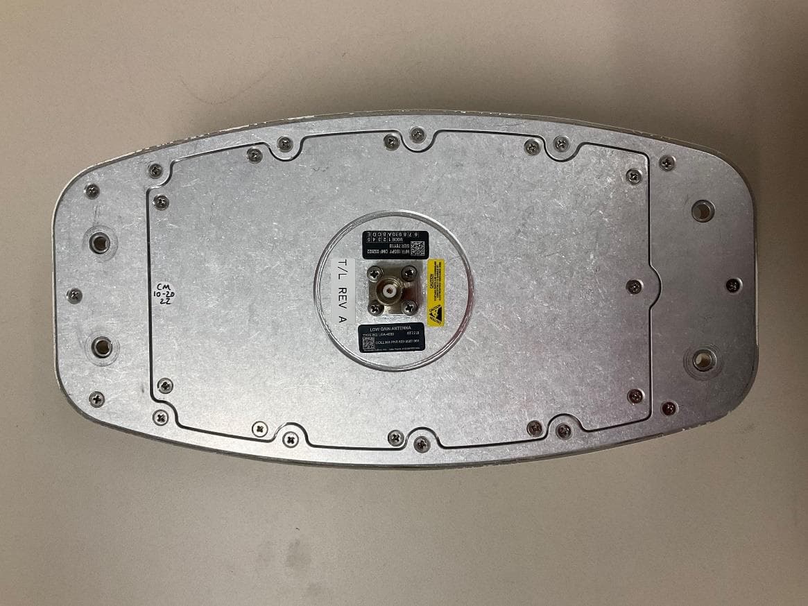
AJK8223587
Jan 23, 2023IRT-4200 SATCOM System
Equipment Class
TNB - Licensed Non-Broadcast Station Transmitter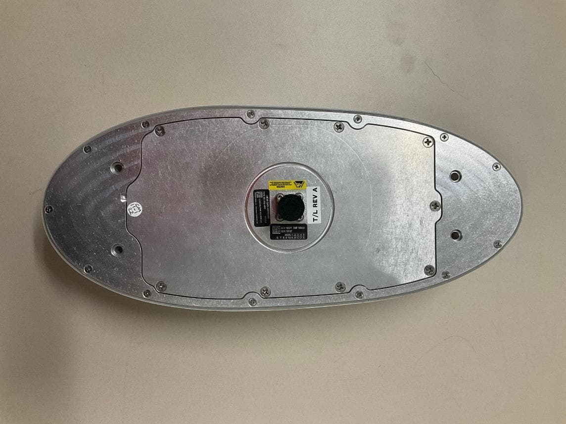
AJK8223586
Jan 23, 2023IRT-4400 SATCOM System
Equipment Class
TNB - Licensed Non-Broadcast Station Transmitter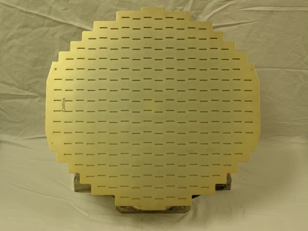
AJK8222259
Nov 11, 2015Weather Radar
Equipment Class
TNB - Licensed Non-Broadcast Station Transmitter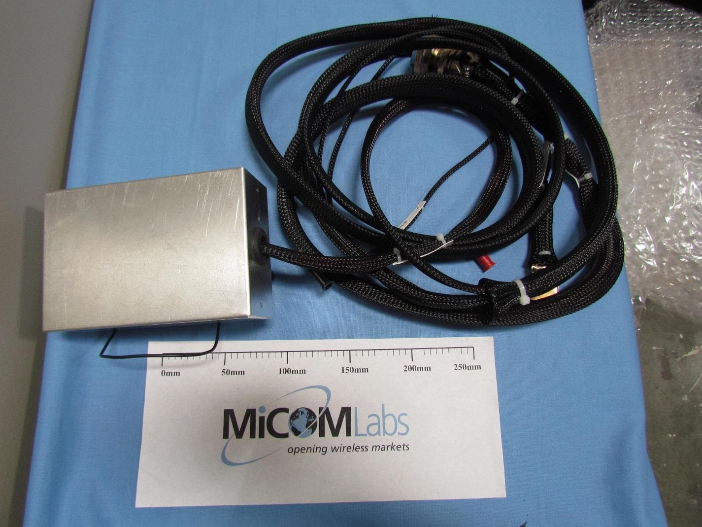
AJK8223132
May 20, 2015Information Management System
Equipment Class
DTS - Digital Transmission System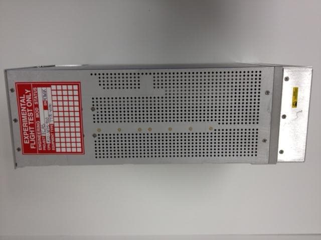
AJK8223075
Mar 04, 2013TCAS II Transmitter/Receiver
Equipment Class
TNB - Licensed Non-Broadcast Station Transmitter