AJK8221293TCAS II
Rockwell Collins Inc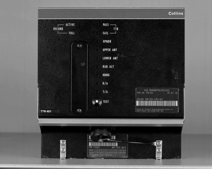
Click to zoom
Application Details
- Equipment Class
- TNB - Licensed Non-Broadcast Station Transmitter
- Date of Grant
- Aug 16, 1999
- Application Purpose
- Original Equipment
- Date of Application
- Jun 07, 1999
- Equipment Note
- TCAS II
- Frequency Range
- 1030.00000000 - 1030.00000000
- Company
- Rockwell Collins Inc
- Country
- United States
Documents & Files
Document Text
Text extracted from the exhibit documents filed with the FCC. Open a document above to read the original.
Users Manual
Rockwell Collins, Inc. Page 10 of 97 Exhibit C – Installation and Operation Manuals Rockwell Collins does not supply operating instructions with the TTR-921 which is designed to meet the requirements of RTCA Specification DO-185A and is operated by trained pilots as a part of air transport aircraft systems. Rockwell Collins does produce a Component Maintenance Manual, Part Number 12-40-69, which, pursuant to an agreement with FCC staff, is available upon request but is not included in this electronic exhibit.
Attestation Statements
Rockwell Collins, Inc. Page 96 of 97 Exhibit J – FAA Notification Pursuant to Section 87.147 Washington Office 1300 Wilson Boulevard, Suite 200 Arlington, VA 22209-2307 703.516.8200 R C June 4, 1999 Federal Aviation Administration Spectrum Engineering Division ASR-200 800 Independence Avenue, SW Washington, DC 20591 Re:FAA Notification of FCC Equipment Approval Under FCC Part 87 Traffic Alert and Collision Avoidance System (TCAS) II TTR-921 & TTR-4000 Transceivers FCC ID: AJK8221293 Gentlemen: In accordance with the Federal Communications Commission (FCC) Rules and Regulations, Part 87.147(d), Rockwell Collins, Inc. hereby notifies the Federal Aviation Administration (FAA) of its simultaneous filing with the FCC of an application for Certification of equipment intended for transmission in frequency ranges set forth in FCC Rules Part 87.147(d)(3) which require FAA notification. The application for Certification covers the Rockwell Collins TTR-921 and TTR-4000 TCAS II transceivers. One complete set of the filing documents is enclosed for your review. Please direct any questions regarding this filing to Mr. Brett Wilson of this office on (703) 516-8223 Respectfully submitted, Linda C. Sadler Director, Governmental & Regulatory Affairs cc:Federal Communications Commission
Cover Letter(s)
Washington Office 1300 Wilson Boulevard, Suite 200 Arlington, VA 22209-2307 R C June 4, 1999 Federal Communications Commission Office of Engineering and Technology Application Filed Via OET Laboratory Electronic Filing Site https://gullfoss.fcc.gov/prod/oet/index.html Re:Equipment Authorization Under Part 87 Certification Traffic Alert and Collision Avoidance System (TCAS) II TTR-921 and TTR-4000 Transceivers FCC ID: AJK8221293 Gentlemen: Rockwell Collins, Inc. (Rockwell Collins) hereby submits an Application for Equipment Authorization for the TTR-921 and -4000 TCAS II transceivers (FCC ID: AJK8221293) using the Office of Engineering and Technology’s online filing system. The difference between TTR-921, which is intended for use in air transport aircraft, and TTR-4000, which is intended for use in general aviation aircraft, is the inclusion of three empty slots for additional electronics in the TTR-921. One complete set of documents covering the TTR-921 and TTR-4000, including a detailed product description and test data, is submitted as part of the Application. Rockwell Collins is sending another complete set of documents to the Federal Aviation Administration (FAA) pursuant to FCC Part 87.147(d). A copy of the transmittal letter to the FAA is enclosed as Exhibit J. Your early consideration of the Application is respectfully requested. Please direct all inquiries to Mr. Brett Wilson of this office at (703) 516-8223. Respectfully submitted, Linda C. Sadler Director, Governmental & Regulatory Affairs
Cover Letter(s)
FCC Certification Report For Collins Types TTR-921 and TTR-4000 TCAS II Receiver-Transmitter May 24, 1999 NOTICE: The contents of this document are proprietary to Rockwell Collins, Inc. and shall not be disclosed, disseminated, copied, or used except for purposes expressly authorized in writing by Rockwell Collins, Inc. Rockwell Collins, Inc. Arlington, Virginia 22209 USA
Cover Letter(s)
Rockwell Collins, Inc. Page 2 of 97 FOREWARD The following information is being submitted in compliance with Part 2 and Part 87 of Title 47, Code of Federal Regulations – Telecommunications, for certification of Rockwell Collins TTR-921 and TTR-4000 TCAS II Receiver-Transmitters. This equipment is intended for quantity production by Rockwell Collins, the sole manufacturer. This submittal covers three Collins part numbers under the TTR-921 type number and one part number under the TTR-4000 type number. The part numbers for the TTR-921 are 822-1293-001, -220, and –320. Software unique to the airframe manufacturers (Boeing, McDonnel Douglas now part of Boeing, and Airbus) differentiates each part number. The part number for the TTR-4000 is 822-1294-001. The TTR-921 is a six MCU size intended for use on larger air transport aircraft. The TTR-4000 is a four MCU size intended for operation on general aviation and regional carrier aircraft.
Cover Letter(s)
Rockwell Collins, Inc. Page 3 of 97 Table of Contents FOREWORD__________________________________________________________2 Table of Contents______________________________________________________3 Exhibit A – Product Description__________________________________________4 Exhibit B - Section 2.1033 (c) Technical Report____________________________5 1. Name and Address___________________________________________________5 2. FCC Identifier ______________________________________________________5 3. Installation and Operation Manuals____________________________________5 4. Type(s) of Emission__________________________________________________5 5. Frequency Range____________________________________________________5 6. Range of Operating Power Values______________________________________6 7. Maximum Power Rating Defined in Part 87______________________________6 8. Final Amplifier DC Voltages and Currents_______________________________6 9. Tune Up Procedures_________________________________________________6 10. Schematics and Circuit Diagrams_____________________________________7 11. Nameplate Bearing the FCC ID and Placement _________________________7 12. Equipment Photographs_____________________________________________7 12.1. External Views____________________________________________________7 12.2. Internal Views____________________________________________________7 13. Description of Modulation System_____________________________________7 14. Required Measurements____________________________________________10 Exhibit C - Installation and Operation Manuals____________________________11 Exhibit D - Tune Up Procedures_________________________________________12 Exhibit E - Schematics and Circuit Diagrams______________________________13 Exhibit F - Nameplate Label Drawing____________________________________42 Exhibit G - Equipment Photographs: External Views_______________________45 Exhibit H - Equipment Photographs: Internal Views________________________49 Exhibit I - Required Measurements______________________________________58 Exhibit J - FAA Notification Pusuant to Section 87.147______________________96
Cover Letter(s)
Washington Office 1300 Wilson Boulevard, Suite 200 Arlington, VA 2220902307 April 11, 1995 Federal Communications Commission Office of Engineering and Technology Application Filed Via OET Laboratory Electronic Filing Site https://gullfoss.fcc.gov/prod/oet/index.html Re:Request for Confidentiality Pursuant to 47 CFR 0.459 and 0.457 Application for Equipment Certification Traffic Collision Avoidance System (TCAS) II TTR-921 and TTR-4000 Transceivers FCC ID: AJK8221293 Gentlemen: In accordance with the provisions of 47 CFR 0.459 and 0.457(d)(2)(i), Rockwell Collins, Inc. hereby requests that Exhibit E – Schematics and Circuit Diagrams of our Application for Equipment Certification for TCAS II TTR-921 and TTR-400 Transceivers be withheld from public inspection. This application was electronically filed on June 8, 1999 and corresponds to Confirmation Number EA94458 and FCC ID AJK8221293. Exhibit E contains confidential commercial information or technical data customarily guarded from competitors and is, therefore, exempt from disclosure under Exemption 4 of the Freedom of Information Act [5 USC 522(b)(4)] because disclosure could reasonably be expected to cause substantial competitive harm. We have included the $135.00 processing fee for requests for confidentiality in our credit card payment for $610.00. Your consideration of this request for confidentiality is respectfully requested. Please direct all inquiries to Mr. Brett Wilson Respectfully submitted, Linda C. Sadler Director, Governmental & Regulatory Affairs
External Photos
Rockwell Collins, Inc. Page 45 of 97 Exhibit G – Equipment Photographs: External Views – 1 –
Internal Photos
Rockwell Collins, Inc. Page 49 of 97 Exhibit H – Equipment Photographs: Internal Views CPU/IO CARD – 1 – Power Supply/Modulator DSP Card Transmitter Module Beam Steering Board Beam Steering Control Card
Operational Description
Rockwell Collins, Inc. Page 4 of 97 Exhibit A – Product Description The TCAS II is an airborne traffic alert and collision avoidance system that interrogates ATC transponders in nearby aircraft and uses computer processing to identify and display potential and predicted collision threats. The system protects a volume of airspace around the TCAS II equipped aircraft and supplies appropriate aural and visual advisories to the flight crew to provide adequate separation when the computer analysis of the intruding aircraft transponder replies predict a penetration of the protected airspace. The system provides two types of advisories: traffic and resolution. Traffic advisories indicate the relative positions of intruding aircraft that are approximately 35 seconds from the closest point of approach and may require a resolution advisory a short time thereafter. Traffic advisories also provide the flight crew the opportunity to visually acquire the intruding aircraft. When the computer predicts that the intruder aircraft is within approximately 25 seconds from the closest approach, a resolution advisory will produce a threat resolution in the form of a vertical maneuver that will increase separation. The system provides traffic and advisory flightdeck displays. The traffic advisory display indicates the relative position of proximate ATC transponder equipped aircraft. The resolution advisory display for each pilot indicates the appropriate vertical maneuver to avoid threat. The TCAS II aircraft must be equipped with a Mode S ATC transponder, which provides necessary air-to-air communications, for coordinating the resolution maneuvers between TCAS equipped aircraft. The Mode S transponder also provides discrete address replies to interrogations from ground stations and other TCAS II equipped aircraft and has the capability to respond to Mode A and Mode C interrogations. The TCAS II system can only generate resolution advisories for intruders with operative Mode S or Mode C transponders, transponders that provide information on the altitude of the intruder. Traffic advisories that display the relative position of the intruder can be generated for aircraft with operative Mode S, Mode C, or Mode A transponders. The TCAS II equipment functions as a supplement to the pilot who, with the aid of the ATC system, has the primary responsibility for avoiding mid-air collisions. The TCAS II system provides no indication of traffic conflicts with aircraft without operative transponders.
Operational Description
Rockwell Collins, Inc. Page 5 of 97 Exhibit B - Section 2.1033 (c) Technical Report 1. Name and Address The name and address of the manufacturer of the TTR-921 and TTR-4000 TCAS II Receiver- Transmitter and applicant for certification is Rockwell Collins, Inc., 1300 Wilson Boulevard, Suite 200, Arlington, Virginia 22209. 2. FCC Identifier FCC ID Description AJK8221293 TCAS II Receiver-Transmitter 3. Installation and Operation Manuals See Exhibit C. 4. Type(s) of Emission The TCAS II emission type is V1D. Pulses emitted by the TTR-921 and TTR-4000 vary in width and amplitude, and contain angle modulation during the pulse. It is a single channel containing digital information without the use of a modulating subcarrier. The type of information transmitted by TCAS II systems is data only. Due to the relatively complex nature of the signals transmitted by the TTR-921 and TTR-4000, there is no one single formula that can predict the necessary bandwidth. The modulation with the fastest temporal characteristic, and thus the greatest effect on frequency domain, is the binary phase shift keying which occurs during Mode S transmission. Sam K. Shanmugam and John Wiley maintain that: “...the shapes of the psd of the binary PSK signal and the ASK signal are similar. The only difference is that the PSK spectrum does not have an impulse at the carrier frequency. The bandwidth requirement of the PSK signal is the same as that of the ASK signal.” 1 Accordingly, we believe the formula from the procedures of Report 836 of the International Radio Consultative Committee, “Recommendations and Reports of the CCIR,” 1982 accurately predicts the necessary bandwidth for a BPSK pulse as well as for an unmodulated pulse. Since the RTCA DO 185-A specifies no minimum switching time, the formula for a rectangular pulse will be used. Considering that the spectrum of a group of pulses falls within the envelope defined by the spectrum of a single pulse, the formula Bn = 6.36 / t is employed, where Bn is the necessary bandwidth, and t is the pulse width. The narrowest chip permitted by RTCA DO-185A has t = 230 nanoseconds. The necessary bandwidth then becomes Bn = 27.65 MHz. Thus the complete emission designation according to Section 2.201 and 2.202 is 27M7V1D. 5. Frequency Range The transmission frequency is 1030 + 0.01 MHz. 1 Shanmugam, Sam K. Wiley, John, "Digital and Analog Communications Systems, " 1979, p. 403. Rockwell Collins, Inc. Page 6 of 97 6. Range of Operating Power Values Assuming full power operation, the total RF power at the TTR-921 and TTR-4000 ARINC RF power terminals is +55.25 dBm maximum and +51.25 dBm minimum. The TTR-921 and TTR-4000 are used in conjunction with standard aircraft systems and with standard TCAS antennas. In a typical installation, the antenna gain is 3.25 dB and the cable loss is 2.5 dB. The power-gain product or Effective Radiated Power (ERP) in the forward direction associated with each radiated transmission pulse shall be a maximum of +56 dBm (400 W), and a minimum of +52 dBm (160 W), assuming full power operation. The power-gain product is related to Total Radiated Power (TRP), a variable used in the interference limiting algorithms, according to the following expression: TRP = P*G(BW/360 deg) where P is the net power delivered to the RF reference point; G is the peak azimuth antenna gain at 0 degrees elevation relative to a matched quarter wave stub (P*G is the power-gain product); and, BW is the 3 dB azimuth beam width in degrees. The specified limit on radiated power is intended to prevent excessive power transmission from causing premature interference limiting and, in turn, an unnecessary reduction in the dynamic range of the whisper-shout sequence. The TCAS transmitter-receiver has a transmit/listen cycle of approximately 1 second. In each cycle, a series of increasing-power mode C interrogations is first transmitted. This is the whisper/shout (w/s) sequence. Either a listen period, or a mode S interrogation or reply followed by a listen period immediately follows. During the listen period, the transmitter-receiver listens for squitter signals and for interrogation replies from other aircraft transponders. If no signals are heard during this listen period, no interrogations or replies are transmitted. If signals are heard, a roll-call list of transmitting aircraft is compiled. (Mode S transponders transmit data that uniquely identifies the replying aircraft. This identification data is used by the TCAS to address only that aircraft when needed.) The transmitter-receiver will, at the beginning of the next interrogate/reply/listen portion of the cycle, transmit interrogations to aircraft in the roll-call list. After the transmission(s), the rest of the cycle is spent in the listen mode. 7. Maximum Power Rating as Defined in Part 87 Section 87.131, Power and emissions, does not specify maximum power for TCAS equipment. Instead, pursuant to table footnote no. 7, frequency, emission, and maximum power will be determined by appropriate standards during the certification process. The appropriate standard for TCAS equipment is RTCA DO-185A. DO-185A calls for effective radiated power (ERP) of 56 dBm (400 watts). Accounting for standard TCAS antenna gain of 3.25 dB and cable loss of 2.5 dB, the maximum total transmitter output should be 55.25 dBm (298.5 watts). 8. Final Amplifier DC Voltages and Currents The final stage consists of a 2-way power splitter, a pair of final transistors, and a 2-way power combiner. The dc voltage for each transistor is 48.0 VDC. The dc current under maximum pulse power conditions is 19.8 Amp DC. 9. Tune Up Procedures See Exhibit D. Rockwell Collins, Inc. Page 7 of 97 10. Schematics and Circuit Diagrams See Exhibit E. 11. Nameplate Bearing the FCC ID and Placement See Exhibit F. 12. Equipment Photographs (2.1033 (c) (12)) 12.1 External Views See Exhibit G. 12.2 Internal Views See Exhibit H. 13. Description of Modulation System Transmit Pulse Characteristi…
Text truncated - open the document above for the full version.
Parts List/Tune Up Info
Rockwell Collins, Inc. Page 11 of 97 Exhibit D – Tune Up Procedures The following tune up procedure is taken from the Production Test Requirements for the TTR- 921/TTR-4000 Transmitter Assembly: TRANSMITTER PEAK POWER TUNING (MODE C) COLLECTOR VOLTAGE ADJUSTMENTS PROCEDURE 1) Set the UUT to mode C transmit mode 2) Set Whisper Shout settings to 0db attenuation 3) Adjust the following pulse and dc voltage levels to within +-0.1vdc 4) Attach oscilloscope probe to E51, adjust modulator R131 for 48vdc 5) Attach oscilloscope probe to E45, adjust modulator R 97 for 32vdc 6) Attach oscilloscope probe to E41, adjust modulator R136 for 45vdc 7) Attach oscilloscope probe to E42, adjust modulator R144 for 45vdc 8) Attach oscilloscope probe to E40, adjust modulator R154 for 45vdc TUNING THE PA PROCEDURE 1) Set the UUT to mode C transmit mode 2) Set Whisper Shout settings to 0db attenuation Caution: Always keep adequate attenuation on RF output at all time because the PA can start Transmitting at any time when the tuning gets close to the correct values. 3) It is suggested to “preset” all tuning caps to the middle of their range before testing. A closer preset condition is to try and match the cap tuning on an already tuned P.A. Usually it is necessary to tap in to the output of Q2 and get Q1 and Q2 tuned first. ( See Note: ) Then, the entire amp chain can usually be tuned. 4) Adjust PA Plate piston caps for peak pulse amplitudes. 5) Output Power 57.95 dbm +/- 0.5 dbm Note: To tune the TCAS PA it may be necessary to “Tap In” to the Amplifier Chain and tune part or parts of the Amplifier Chain individually. This is done by desoldering a series cap, rotating it 90 degrees, and soldering it to the center conductor of a tune stub (a piece of RG316 coaxial cable 6” to 8” long with a SMA connector on one end.). The shield of the coaxial cable is soldered to ground. Connect SMA connector through correct attenuators to Power Meter. Use the following chart as guide for tuning PA using this procedure. Stage Input Tune Cap Output Tune Cap Series Cap Rotate 90 Deg. Approximate Power Output Q1 C15 C8 C7 31.5 dbm Q2 C9 C10 C12 40.5 dbm Q3 C16 C17 C21 48.0 dbm Q4 C24 C27 C28 53.5 dbm Q5 and Q6 C46 and C48 C49 and C53 None 60.7 dbm
Test Report
Rockwell Collins, Inc. Page 58 of 97 Exhibit I – Required Measurements Sec. 2.1046 Measurement required: RF power output When measured at the RF output terminals of the TTR-921/TTR-4000 the output power shall be: Minimum RF power : +51.25 dBm (149.6 W) Nominal RF power : +53.25 dBm (211.3 W) Maximum RF power : +55.25 dBm (298.5 W) Test Setup 429 Box Top Antenna Ports UUT Bottom Antenna Ports Combiner Atten1 (20) Power Sensor Peak Power Meter Oscilloscope 50 ohm 50 ohm 50 ohm 50 ohm Coupler Detector Atten2 (10) Atten4 (6) Atten3 (10) Test Equipment 429 Box – Atlantic Instruments Datatrac 400. Combiner - Four way power combiner configured with 0, -45, -45, and –135 degree inputs. Attenuator 1 - 50 Ohm power attenuator, 20 dB nominal. Attenuator 2 - 50 Ohm power attenuator, 10 dB nominal Attenuator 3 - 50 Ohm power attenuator, 10 dB nominal. Attenuator 4 - 50 Ohm power attenuator, 6 dB nominal. Coupler – Narda 3002-10 Rockwell Collins, Inc. Page 60 of 97 Power Sensor – Gigatronics 80350A Peak Power Sensor Peak Power Meter – Gigatronics 8542C Universal Power Meter Oscilloscope – Techtronics TDS 754C Detector – HP423B 50 Ohm – 50 Ohm power termination Test Procedure The power meter was calibrated to indicate the power output directly with the particular attenuators and coupler used. Proper programming of the 429 box accesses the following test modes: (1) Mode C Test Mode 1 – A standard Mode C only all-call interrogation at a rate of 50 per second, nominal. (2) Mode S Test Mode 1 – A Mode S interrogation format with a short P6 pulse but containing a data block whose bit values are all one. The interrogation rate is 50 per second, nominal. The top antenna ports are connected to the combiner as follows: Ch1 0, Ch2 -45, Ch3 -135, Ch4 – 45. This is the Top/Forward configuration. Power was measured for both test modes. The combiner was then moved to the bottom antenna ports and connected as above, resulting in the Bottom/Forward configuration. The 50 Ohm loads were moved to the top antenna ports. Power was again measured for both test modes. Data MCN: E005 Date: 4/23/99 Tested By: K.S. Test ModePulsePower Output Top Ant. dBm (Watts) Power Output Bottom Ant. dBm (Watts) 1 P 1 P 2 P 3 53.95 (248.3) 53.80 (239.9) 53.90 (245.5) 54.05 (254.1) 53.89 (243.2) 54.02 (252.3) 2 P 1 P 2 P 3 53.96 (248.9) 53.97 (249.5) 53.91 (246.0) 54.05 (254.1) 54.05 (254.1) 53.99 (250.6) Sec. 2.1047 Measurement required: Modulation characteristics The TTR-921/TTR-4000 output consists of pulse groups whose attributes are defined by RTCA DO-185A. Transmissions fall into two categories - TCAS to Mode C transmissions and TCAS to Mode S transmissions. See Exhibit B, Item (13) for a description and requirements for the modulation characteristics. Test Setup (Amplitude characteristics) 429 Box Top Antenna Ports UUT Bottom Antenna Ports Combiner Atten1 (20) Power Sensor Peak Power Meter Oscilloscope 50 ohm 50 ohm 50 ohm 50 ohm Coupler Detector Atten2 (10) Atten4 (6) Atten3 (10) Test Equipment (Amplitude characteristics) 429 Box – Atlantic Instruments Datatrac 400. Combiner - Four way power combiner configured with 0, -45, -45, and –135 degree inputs. Attenuator 1 - 50 Ohm power attenuator, 20 dB nominal. Attenuator 2 - 50 Ohm power attenuator, 10 dB nominal Attenuator 3 - 50 Ohm power attenuator, 10 dB nominal. Attenuator 4 - 50 Ohm power attenuator, 6 dB nominal. Coupler – Narda 3002-10 Power Sensor – Gigatronics 80350A Peak Power Sensor Peak Power Meter – Gigatronics 8542C Universal Power Meter Oscilloscope – Techtronics TDS 754C Rockwell Collins, Inc. Page 62 of 97 Detector – HP423B 50 Ohm – 50 Ohm power termination Test Procedure (Amplitude characteristics) The power was calibrated to indicate the power output directly with the particular attenuators and coupler used. Proper programming of the 429 box accesses the following test modes: (1) Mode C Test Mode 1 – A standard Mode C only all-call interrogation at a rate of 50 per second, nominal. (2) Mode S Test Mode 1 – A Mode S interrogation format with a short P6 pulse but containing a data block whose bit values are all one. The interrogation rate is 50 per second, nominal. (3) Mode S Test Mode 2 – A Mode S interrogation format with a long P6 pulse but containing a data block whose bit values are all one. The interrogation rate is 50 per second, nominal. The top antenna ports are connected to the combiner as follows: Ch1 0, Ch2 -45, Ch3 -135, Ch4 – 45. This is the Top/Forward configuration. Photos and data were taken to show the pulse shapes in each of the three test modes. The combiner was then moved to the bottom antenna ports and connected as above, resulting in the Bottom/Forward configuration. The 50 Ohm loads were moved to the top antenna ports. Photos and data were again taken to show the pulse shapes in each of the three test modes. Rockwell Collins, Inc. Page 63 of 97 Data (Amplitude characteristics) MCN: E005 Date: 4/23/99 Tested By: K.S. Figures show the detected envelopes for the three test modes from the top antenna and bottom antenna. Data were as follows: Mode C Top Antenna S 1 P 1 P 3 P 4 Pulse amplitude 53.2753.9453.7453.89dBm Pulse width 0.806 0.8020.7920.788usec Rise time 0.055 0.0570.0590.057usec Fall time 0.078 0.0770.0770.078usec S 1 to P 1 ref2.00usec P 1 to P 3 ref21.01usec P 3 to P 4 ref2.00usec Bottom Antenna S 1 P 1 P 3 P 4 Pulse amplitude 53.5054.1653.9954.12dBm Pulse width 0.806 0.8020.7930.788usec Rise time 0.056 0.0570.0600.057usec Fall time 0.078 0.0790.0780.078usec S 1 to P 1 ref2.00usec P 1 to P 3 ref21.01usec P 3 to P 4 ref2.00usec Mode S Top Antenna P 1 P 2 P 6 Amplitude var. and droop Ref+0.01-0.05dB (P 6 at 1usec) Rise time 0.059 0.0580.056usec Fall Time 0.079 0.0800.081usec Pulse width Short P 6 0.8060.801 16.17usec Long P 6 30.17usec P 1 to P 2 spacing ref2.00usec Sync phase reversal ref 2.76usec Phase reversal duration 0.053 usec P 6 leading edge from sync 1.260usec Chip guard interval 0.660 Usec Bottom Antenna P 1 P 2 P 6 Amplitude var. a…
Text truncated - open the document above for the full version.
Contact Information
Applicant
Thomas A. Voltero(Senior Counsel)
Technical Contact
Rockwell Collins, Inc.Brett Wilson
[email protected](703) 516-8223
1300 Wilson Boulevard · Arlington, Virginia · United States
Non-Technical Contact
Rockwell Collins, Inc.Brett Wilson
[email protected](703) 516-8223
Technical Specifications
| # | Rule Parts | Frequency Range | Power Output | Emission | Tolerance |
|---|---|---|---|---|---|
| 1 | 87 | 1.03 GHz - 1.03 GHz | 298.5 W | 27M7V1D | 10000.0000000000 Hz |
Other Applications from Rockwell Collins Inc
AJK8223587
Jan 23, 2023IRT-4200 SATCOM System
Equipment Class
TNB - Licensed Non-Broadcast Station Transmitter
AJK8223586
Jan 23, 2023IRT-4400 SATCOM System
Equipment Class
TNB - Licensed Non-Broadcast Station Transmitter
AJK8222259
Nov 11, 2015Weather Radar
Equipment Class
TNB - Licensed Non-Broadcast Station Transmitter
AJK8223132
May 20, 2015Information Management System
Equipment Class
DTS - Digital Transmission System
AJK8223075
Mar 04, 2013TCAS II Transmitter/Receiver
Equipment Class
TNB - Licensed Non-Broadcast Station Transmitter