AJK8221349SRT-2000 Satellite Receiver-Transmitter
Rockwell Collins Inc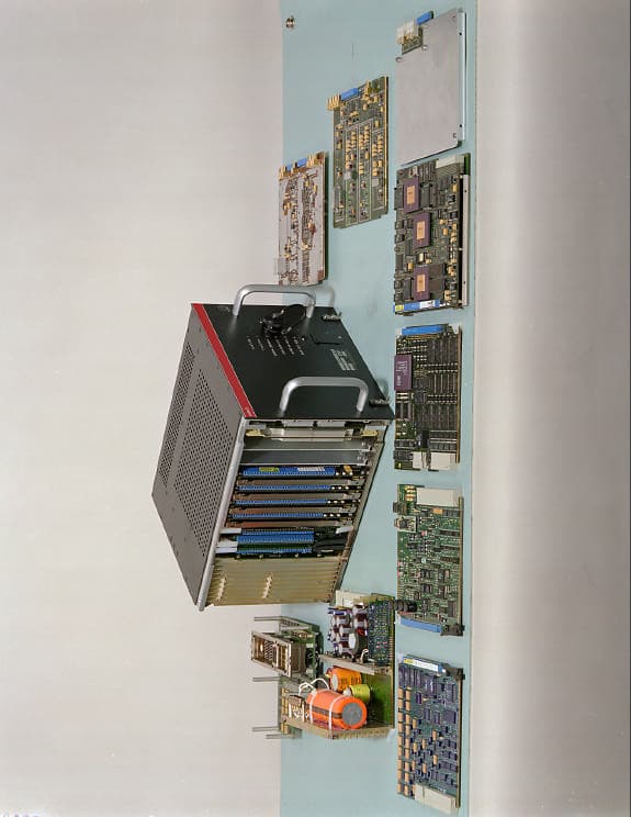
Click to zoom
Application Details
- Equipment Class
- TNB - Licensed Non-Broadcast Station Transmitter
- Date of Grant
- Nov 17, 1999
- Application Purpose
- Original Equipment
- Date of Application
- Jun 30, 1999
- Equipment Note
- SRT-2000 Satellite Receiver-Transmitter
- Frequency Range
- 1626.50000000 - 1660.50000000
- Company
- Rockwell Collins Inc
- Country
- United States
Documents & Files
Document Text
Text extracted from the exhibit documents filed with the FCC. Open a document above to read the original.
Users Manual
CPN: 832-5150-001 Rev:- Rockwell Collins, Inc. Page 19 of 232 Exhibit 3 – Installation and Operating Manuals Rockwell Collins does not supply operating instructions with the SRT-2000, which is designed to meet the requirements of ARINC 429, 600, 604, and 741, and RTCA documents DO-160D, and DO-178B and is operated by trained pilots as part of standard, Douglas, and Airbus aircraft systems. Rockwell Collins does produce a comprehensive installation manual which, pursuant to an agreement with the FCC staff, is available upon request but is not included in this electronic exhibit.
Cover Letter(s)
FCC Type Acceptance Report For SRT-2000 Satellite Communications System CPN: 832-7459-001 Rev: - July 1, 1999 NOTICE: The contents of this document are proprietary to Rockwell Collins, Inc. and shall not be disclosed, disseminated, copied, or used except for purposes expressly authorized in writing by Rockwell Collins, Inc. exchanged. Rockwell Collins, Inc. Arlington, Virginia 22209, USA
Cover Letter(s)
CPN: 832-5150-001 Rev:- Rockwell Collins, Inc. Page 3 of 195 Foreword The following information is being submitted in compliance with Part 2 and Part 87 of Title 47, Code of Federal Regulations – Telecommunications, for certification of Rockwell Collins Satellite Receiver/Transmitter in the SRT2000. Satellite Data Unit Number of Part Number Model Number Channels Standard Douglas Airbus SRT-2000-1 1 822-1404-001 822-1404-3xx 822-1404-4xx SRT-2000-2 2 822-1346-001 822-1346-3xx 822-1346-4xx SRT-2000-3 3 822-1405-001 822-1405-3xx 822-1405-4xx SRT-2000-4 4 822-1348-001 822-1348-3xx 822-1348-4xx SRT-2000-5 5 822-1406-001 822-1406-3xx 822-1406-4xx SRT-2000-6 6 822-1349-001 822-1349-3xx 822-1349-4xx The Standard part numbers are intended for airlines installing systems by STC or systems to be certified on Boeing Commercial Aircraft Group (BCAG) aircraft. These installations track installed software by Service Bulletin. The Douglas and Airbus part numbers are intended for equipment to be certified and aircraft produced by the Douglas Products Division (DPD) of Boeing, and by Airbus; respectively. These companies require the top-level part number to reflect the installed software revision. The initial release is anticipated to be –301 and –401, respectively. The units tested for the purposes of this report were engineering units representative of production configurations.
Cover Letter(s)
Washington Office 1300 Wilson Boulevard, Suite 200 Arlington, VA 22209-2307 703.516.8200 R C July 1, 1999 Federal Aviation Administration Spectrum Engineering Division ASR-200 800 Independence Avenue, SW Washington, DC 20591 Re:FAA Notification of FCC Equipment Approval Under FCC Part 87 SRT-2000 INMARSAT AREO-I Transceiver FCC ID: AJK8221349 Gentlemen: In accordance with the Federal Communications Commission (FCC) Rules and Regulations, Part 87.147(d), Rockwell Collins, Inc. hereby notifies the Federal Aviation Administration (FAA) of its simultaneous filing with the FCC of an application for Certification of the SRT- 2000 INMARSAT AERO-I Transceiver. The SRT-2000 is intended to transmit on frequencies set forth in Section 87.247 (d)(3). One complete set of the filing documents is enclosed for your review. Please direct any questions regarding this filing to Mr. Brett Wilson of this office on (703) 516-8223 Respectfully submitted, Linda C. Sadler Director, Governmental & Regulatory Affairs cc:Federal Communications Commission
Cover Letter(s)
Washington Office 1300 Wilson Boulevard, Suite 200 Arlington, VA 22209-2307 R C July 1, 1999 Federal Communications Commission Office of Engineering and Technology Application Filed Via OET Laboratory Electronic Filing Site https://gullfoss.fcc.gov/prod/oet/index.html Re:Equipment Authorization Under Part 87 Certification SRT-2000 INMARSAT AERO-I Transceiver FCC ID: AJK8221349 Gentlemen: Rockwell Collins, Inc. (Rockwell Collins) hereby submits an Application for Equipment Authorization for the SRT-2000 INMARSAT AERO-I transceiver (FCC ID: AJK8221349) using the Office of Engineering and Technology’s online filing system. The SRT-2000 covered in this application for certification can be configured to operate with up to six simultaneous channels of communication (1 data channel and 5 voice channels) with a ground earth station. One complete set of documents covering the SRT-2000, including a detailed product description and test data, is submitted as part of the Application. Rockwell Collins is sending another complete set of documents to the Federal Aviation Administration (FAA) pursuant to FCC Part 87.147(d). A copy of the transmittal letter to the FAA is enclosed as Exhibit 10. Your early consideration of the Application is respectfully requested. Please direct all inquiries to Mr. Brett Wilson of this office at (703) 516-8223. Respectfully submitted, Linda C. Sadler Director, Governmental & Regulatory Affairs
Cover Letter(s)
Washington Office 1300 Wilson Boulevard, Suite 200 Arlington, VA 22209-2307 R C June 11, 2001 Federal Communications Commission Office of Engineering and Technology Application Filed Via OET Laboratory Electronic Filing Site https://gullfoss.fcc.gov/prod/oet/index.html Re:Equipment Authorization Under Part 87 Certification SRT-2000 INMARSAT AERO-I Transceiver FCC ID: AJK8221349 Gentlemen: In accordance with the provisions of 47 CFR 0.459 and 0.457(d)(2)(I), Rockwell Collins, Inc. hereby request that Exhibit 4 – Tune Up Procedures and Exhibit 5 – Schematics and Circuit Diagrams of our Application for Equipment Certification for SRT-2000 Satellite Receiver/Transmitter be withheld from public inspection. This application was electronically filed on July 1, 1999 and corresponds to Confirmation Number EA94716 and FCC ID AJK8221349. Exhibit 4 and 5 contain confidential commercial information or technical data customarily guarded from competitors and is, therefore, exempt from disclosure under Exemption 4 of the Freedom of Information Act [5 USC 522(b)(4)] because disclosure could reasonably be expected to cause substantial competitive harm. Please note that Exhibit 5 (Schematics and Circuit Diagrams) was broken into six electronic files labeled Exhibit 5a – f in order to overcome technical difficulties in uploading Exhibit 5 to the OET Laboratory Electronic Filing Site. We seek to confidential treatment for all of the schematics submitted under Exhibit 5. Your early consideration of the Application is respectfully requested. Please direct all inquiries to Mr. Brett Wilson of this office at (703) 516-8223. Respectfully submitted, Linda C. Sadler Director, Governmental & Regulatory Affairs
Cover Letter(s)
APPLICATION FOR CERTIFICATION OF ROCKWELL COLLINS SRT-2000 FCC ID: AJK8221349 LIST OF EXHIBITS AND INFORMATION UPLOADED TO FCC The following list of exhibits and other information related to Rockwell Collins Application for Certification for the SRT-2000 was uploaded to the OET Electronic Filing Site on July 1 and July 2, 1999. Please contact Brett Wilson on (703) 516-8223 if any information is missing or otherwise unavailable. Cover Letter to the FCC Letter to the FCC Requesting Confidentiality for Exhibits 4 and 5 Exhibit 1 Product Description Exhibit 2 Technical Report Exhibit 3 Installation and Operating Manual Exhibit 4 Tune Up Procedures Exhibit 5 Schematics We had technical difficulty uploading this exhibit to the electronic filing site. Consequently, we broke it up into the 6 following files: Exhibit 5a Schematics Exhibit 5b Schematics Exhibit 5c Schematics Exhibit 5d Schematics Exhibit 5e Schematics Exhibit 5f Schematics Exhibit 6 Nameplate Label Drawing Exhibit 7 Equipment Photographs – External Exhibit 8 Equipment Photographs – Internal Exhibit 9 Required Measurements Exhibit 10 FAA Notification Cover Letter
External Photos
CPN: 832-5150-001 Rev:- Rockwell Collins, Inc. Page 119 of 232 Exhibit 7 – Equipment Photographs: External Views Item Photograph Description Figure 7-1 SRT-2000 Front Panel Figure 7-2 SRT-2000 with Side Cover Removed Figure 7-3 SRT-2000 with Complement of Card Assemblies Figure 7-1 SRT-2000 Front Panel Figure 7-2 SRT-2000 with Side Cover Removed Figure 7-3 SRT-2000 Complement of Card Assemblies
ID Label/Location Info
CPN: 832-5150-001 Rev:- Rockwell Collins, Inc. Page 116 of 232 Exhibit 6 – Nameplate Label Drawing The following are examples of SRT-2000 nameplates with part numbers designating configurations with from one to six channel modules. A Serial Number/Modification Plate is also shown for reference only. CPN: 832-5150-001 Rev:- Rockwell Collins, Inc. Page 117 of 232 CPN: 832-5150-001 Rev:- Rockwell Collins, Inc. Page 118 of 232
Internal Photos
CPN: 832-5150-001 Rev:- Rockwell Collins, Inc. Page 123 of 232 Exhibit 8 - Equipment Photographs: Internal Views Item Photograph Description Figure 8-1 Dummy Card Assembly – This card provides the necessary interface connection to other components when a slot space is not used for a given module Figure 8-2 CEPT – E1 Card Assembly Figure 8-3 System Processor Card Assembly Figure 8-4 Channel Module Card Assembly Figure 8-5 V. C. O Card Assembly Figure 8-6 Up/Down Converter Card Assembly (Top View) Figure 8-7 Up/Down Converter Card Assembly (Bottom View) Figure 8-8 Rear Interconnect Card Assembly Figure 8-9 HPA Card Assembly Figure 8-10 Power Supply Card Assembly Figure 8-11 429 I/O Card Assembly Figure 8-1 Dummy Card Assembly Figure 8-2 CEPT-E1 Card Assembly Figure 8-3 System Processor Card Assembly Figure 8-4 Channel Module Card Assembly Figure 8-5 V. C. O. Card Assembly Figure 8-6 Up/Down Converter Card Assembly (Top View) Figure 8-7 Up/Down Converter Card Assembly (Bottom View) Figure 8-8 Rear Interconnect Card Assembly Figure 8-9 High Power Amplifier (HPA) Card Assembly Figure 8-10 Power Supply Card Assembly Figure 8-11 429 I/O Card Assembly
Operational Description
CPN: 832-5150-001 Rev:-Rockwell Collins, Inc.Page 13 of 232 Exhibit 2 – Technical Report 2.1 Name and Address (Section 2.1033 (c) (1)) The name and address of the manufacturer of the SRT-2000 Satellite Communications System and applicant for certification is Rockwell Collins, Inc., 1300 Wilson Boulevard, Suite 200, Arlington, Virginia 22209. 2.2 FCC Identifier (Section 2.1033 (c) (2)) FCC ID AJK8221349 is the FCC ID for all part numbers of the SRT-2000 with configurations of 1-6 channel modules. 2.3 Installation and Operation Manuals (Section 2.1033 (c) (3)) See Exhibit 3. 2.4 Type or Types of Emission (Section 2.1033 (c) (4)) The following table shows the measured bandwidths for each of the data rates supported by the SRT-2000. Each measured bandwith falls within the 25 kHz bandwidth limit specified in Section 87.137(a) for 21K0G1D, 21K0G1E, and 21K0G1W transmission. This data was obtained while transmitting at the maximum output power of 25 watts. Data Rate (BPS) Low-Band (1626.5 MHz) BW (kHz) Mid-Band (1643.5 MHz) BW (kHz) High-Band (1660.5 MHz) BW (kHz) 6001.1251.1251.125 12001.7501.6251.875 84005.3755.3755.375 105006.6256.6256.625 2100016.50016.25016.250 CPN: 832-5150-001 Rev:-Rockwell Collins, Inc.Page 14 of 232 2.5 Frequency Range (Section 2.1033 (c) (5)) The SRT-2000 frequency range is 1626.5 MHz to 1660.5 MHz when in transmit mode and 1530.0 MHz to 1559.0 MHz when in receive mode. 2.6 Range of Operating Power Values (Section 2.1033 (c) (6)) The SRT-2000 maximum transmitter output power for all transmit channels is 25 Watts / 14 dBW / 44 dBm. The output power level of each module in the transmit mode is individually controlled. The transmit output power adjustment range of each module is from 0 dB to –15dB. 2.7 Maximum Power Rating as Defined in Part 87 According to Section 87.131, UHF aircraft earth stations with emission designators G1D, G1E and G1W can have a maximum of 60 watts per carrier. The SRT-2000 provides a maximum output power of 25 Watts in multi-channel mode. 2.8 DC Voltages and Currents (Section 2.1033 (c) (8)) DC Supply Voltage Maximum DC Supply Current Typical Measured DC Supply Current +25 VDC4.80 Amps4.65 Amps +15 VDC0.45 Amps0.34 Amps -15 VDC0.15 Amps0.08 Amps +5 VDC0.015 Amps.007 Amps 2.9 Tune Up Procedures (Section 2.1033 (c) (9)) See Exhibit 4. CPN: 832-5150-001 Rev:-Rockwell Collins, Inc.Page 15 of 232 2.10 Schematics and Circuit Diagrams (Section 2.1033 (c) (10)) See Exhibit 5. 2.11 Nameplate Label Drawings (Section 2.1033 (c) (11)) See Exhibit 6. 2.12 Equipment Photographs: External Views (Section 2.1033 (c) (12)) See Exhibit 7. 2.13 Equipment Photographs: Internal Views (Section 2.1033 (c) (12)) See Exhibit 8. 2.14 Digital Modulation System (Section 2.1033 (c) (13)) The following describes the digital modulation techniques utilized in the SRT- 2000 for each data rate per Section 2.1033 (c) (13). 600 BPS A-BPSK with differential encoding Square Root 40% Raised Cosine Filter Input wavetrain formulation: The input binary data stream is first applied to a scrambler with a 15-stage shift register which has a feedback polynomial of 1 + X + X 15 . The output of the scrambler is then applied to a convolutional encoder. The generator polynomials are: G1: 1 + X 2 + X 3 + X 5 + X 6 G2: 1 + X + X 2 + X 3 + X 6 The generated polynomial outputs are combined in a punctuated 1/2 rate before the encoded data stream is applied to an interleaver of block size of 384 bits in 6 columns. The output bit stream of the interleaver is organized into words of 3 CPN: 832-5150-001 Rev:-Rockwell Collins, Inc.Page 16 of 232 blocks of 384 bits each. The 3 blocks of data are preceded by a 4 bit format identifier and a 12 bit superframe counter and is appended with a 32 bit unique word for a total word length of 1200 bits. Four (4) words are subsequently organized into a superframe before it is applied to the modulator. The binary phase shift keying (BPSK) modulator phase shifts a subcarrier by -90 or +90 degrees depending on the input word data bit being a 0 or 1, respectively. The subcarrier signal now contains the information and is upconverted for transmission. 1200 BPS A-BPSK with differential encoding Square Root 40% Raised Cosine Filter Input wavetrain formulation: The input binary data stream is first applied to a scrambler with a 15-stage shift register which has a feedback polynomial of 1 + X + X 15 . The output of the scrambler is then applied to a convolutional encoder. The generator polynomials are: G1: 1 + X 2 + X 3 + X 5 + X 6 G2: 1 + X + X 2 + X 3 + X 6 The generated polynomial outputs are combined in a punctuated 1/2 rate before the encoded data stream is applied to an interleaver of block size of 576 bits in 9 columns. The output bit stream of the interleaver is organized into words of 2 blocks of 576 bits each. The 2 blocks of data are preceded by a 4 bit format identifier and a 12 bit superframe counter and is appended with a 32 bit unique word for a total word length of 1200 bits. Eight (8) words are subsequently organized into a superframe before it is applied to the modulator. The binary phase shift keying (BPSK) modulator phase shifts a subcarrier signal by -90 or +90 degrees depending on the input word data bit being a 0 or 1, respectively. The subcarrier signal now contains the information and is upconverted for transmission. 8400 BPS Aviation Quadrature Phase Shift Keying (A-QPSK) Square Root 60% Raised Cosine Filter Input wavetrain formulation: The input binary data stream is first applied to a scrambler with a 15-stage shift register which has a feedback polynomial of 1 + X + X 15 . The output of the scrambler is then applied to a convolutional encoder. The generator polynomials are: G1: 1 + X 2 + X 3 + X 5 + X 6 G2: 1 + X + X 2 + X 3 + X 6 The generated polynomial outputs are combined in a punctuated 2/3 rate before the encoded data stream is applied to an interleaver of block size of 256 bits in 4 columns. The bit stream of the output of the interleaver is…
Text truncated - open the document above for the full version.
Operational Description
CPN: 832-5150-001 Rev:-Rockwell Collins, Inc.Page 4 of 232 Exhibit 1 - Product Description SRT-2000 The SAT-2000 Satellite Communications System, an all solid-state aircraft earth station (AES) that operates as part of the SATCOM system, is designed to be compatible with the INMARSAT AERO-I services. The SAT-2000 system consists of the SRT-2000 Satellite Data Unit and IGA-2000 Intermediate Gain Antenna. The SRT-2000 is a multi-channel receiver-transmitter that provides both voice and data channel to its users. The IGA-2000 Intermediate Gain Antenna allows the SAT-2000 to transmit and receive data and voice traffic efficiently; the diplexer/low noise amplifier is integrated into the antenna to improve system performance and reduce the number of line replaceable units (LRU). Aero-I is intended for medium and short-haul airliners, but is also suitable for aircraft in the long-haul market, which fly mainly within the spot beam coverage. The use of a smaller system allows the SAT-2000 to take advantage of the spot beam feature of the Aero-I satellites to provide the benefits of telephony, fax, and real-time data communications. The SAT-2000 system has a 25 W high power amplifier (HPA) that supports up to six channels (1 data - 5 voice) within the spot beams. 1.1 SRT-2000 Satellite Receiver-Transmitter The SRT-2000 transmits and receives packet mode data to/from the data link system (ACARS or CMU), and receives and transmits circuit mode services (voice) in analog form to/from the flight crew headphones and microphones via the audio management unit(AMU). Additionally, the SRT-2000 receives and transmits circuit mode data (voice, FAX, or PC MODEM) from passengers via an ARINC 746 compatible cabin telephone unit (CTU). Support of secure voice using STU-III compatible telephones is also available with the installation of an optional Cabin Interface Unit (CIU-906). The system also includes interfaces to optional on-board maintenance systems (CMC, CFDS, etc.) for system fault annunciation. The SRT-2000 incorporates the ARINC 741 defined functions of the high power amplifier, RF unit (RFU), beam steering unit (BSU), and satellite data unit (SDU) into a single 8 MCU unit that weighs less than 35 lbs. CPN: 832-5150-001 Rev:-Rockwell Collins, Inc.Page 5 of 232 The SDU function of the SRT-2000 is the interface to all other aircraft systems. It contains all data processing functions, modems and channel tuning synthesizers including a voice CODEC (coder-decoder) and synthesizer pair for each voice channel. The RFU function converts the broadband intermediate frequency (IF) from the SDU portion to L-band frequency before the signal is applied to the HPA function of the SRT-2000. The RFU function also accepts an amplified L-band signal from the low noise amplifier (LNA)/Diplexer and down converts it to the IF used by the SDU function. The HPA function amplifies the signal for transmission. The HPA function feeds a measurement of the actual power transmitted back to the SDU function. The SDU function uses this measurement for power management. The SRT-2000 also contains a 10.24-MHz high stability reference (HSR). The HSR generates high precision injection frequencies and digital clocks from this reference. CPN: 832-5150-001 Rev:- Rockwell Collins, Inc. Page 6 of 232 1.2 Equipment Specifications CHARACTERISTIC SPECIFICATION Physical Size 8 MCU Weight Less than 35 LB (6-channels) Electrical Input Power 97 to 134 VAC, 400 @ 40 Hz, single phase or + 28 VDC Receiver input Frequency range 1530 - 1559 MHz VSWR 2:1 max over input frequency range, 50 Ohms nominal Transmitter output Frequency range 1626.5 to 1660.5 MHz Output level 25 watts (maximum) CPN: 832-5150-001 Rev:-Rockwell Collins, Inc.Page 7 of 232 1.3 Hardware Overview The block diagram below shows the function partitioning of the SRT-2000. 1.4 Mechanical The SRT-2000 is housed in an 8-MCU-size unit with mounting requirements according to the ARINC 600 specification. The front panel contains a standard ARINC 615 dataloader connector and a set of LEDs to indicate unit and system status. It also contains a “self-test” button and corresponding LED indicators for active operator maintenance. Electrical connections are made through an ARINC 761 compliant, ARINC 600 rear connector. CPN: 832-5150-001 Rev:-Rockwell Collins, Inc.Page 8 of 232 The unit consists of a power supply module, RFU module, HPA module, HSR, system processor, ARINC 429/Discrete input/output module, and channel modules. The functions are partitioned into logical functions on circuit cards. The removable, plug-in circuit cards mate with a sideboard interconnect card. The circuit cards are all connected together via a system address bus and system data bus. The design of the unit architecture specifically allows many of the processing functions to be accomplished digitally by the microprocessors and associated memory circuits. 1.5 System Processor Module The system processor maintains the same architectural design as the SDU-906 Satellite Data Unit. It provides high-level system processing and controls communications with all slave processors; it can reset or reprogram any of the slave processors. In addition to processing the signal strength and amplitude information to support the RFU module, the system processor performs the following functions: (1) power control and attenuator control functions; (2) data control and routing; (3) user interfacing for selection of system parameters; and, (4) antenna steering and pointing computations. The system processor accesses all memory-mapped devices in the other modules as if those devices were located in the system processor module. It interfaces to the other modules in the unit through a 24-MHz multiplexed address/data bus. Through this bus, the system processor communicates with the CEPT function, the ARINC 429 function, and the DSPs of each channel module. One interface is common to all the modules. The system processor does not allow the other proce…
Text truncated - open the document above for the full version.
Test Report
CPN: 832-5150-001 Rev:- Rockwell Collins, Inc. Page 135 of 232 Exhibit 9 – Required Measurements 9.1 Test Procedure and Compliance Matrix This section details the test procedures and the test results that are concurrent and beyond the individual LRU test procedures/results. The Rockwell Collins LRU test procedures have been amended to include the FCC requirements described in Parts 2 and 87 of FCC Rules and Regulations. The table below identifies the applicable sections of this document and its relationship between the Parts 2 and 87 requirements. The test results are appended to the individual test sections. 9.2 Test Requirements Matrix FCC Part 2 Section FCC Part 87 Section Test Description Summary Section 2.1046 87.131 RF Power Output 9.4 2.1047 87.141 Modulation Characteristics 9.5 2.1049 87.135 Occupied Bandwidth 9.6 2.1051 87.139 Spurious Emissions at Antenna Terminals 9.7 2.1053 87.139 Field Strength of Spurious Radiation 9.8 2.1055 87.133 Frequency Stability 9.9 2.1057 87.139 Frequency Spectrum 9.10 N/A 87.187 (q) Priority and Preemption 9.11 CPN: 832-5150-001 Rev:- Rockwell Collins, Inc. Page 136 of 232 9.3 Test Equipment The test equipment listed in the following table was used to conduct the operational performance tests indicated herein and for collecting data except where shown differently in individual sections of this report. The actual test setups for each test are described in the individual sections. Item Description Item Number Manufacturer and Model IP-PC 286 or equivalent Logging PC 286 or equivalent MIDU CPN 622-8587-008 SRT-2000 - Rockwell Collins Spectrum Analyzer HP 8544 Spectrum Analyzer HP8566B Or equivalent Power Sensor HP 8481A Or equivalent GES Simulator 622-9760-00x Translator Panel Rockwell Collins Custom 30 dB pad, 25 Watt pad 20 dB pad 10 MHz high stability reference (stability > 19.2 PPB) 30 dB pad, 25 Watt pad Qual Test rack or equivalent HP Power Meter SRT-2000 Qual test station or equivalent Rockwell Collins Custom PHASE NOISE MEASUREMENT SYSTEM HP3048A PHASE NOISE INTERFACE HP11848A DYNAMIC SIGNAL ANALYZER HP3561A HP3048A SOFTWARE VERSION:REV:A.02.00 SYSTEM COMPUTER HP98580B RF SIGNAL GENERATOR HP8663 BROADBAND AMPLIFIER HP8447A PLOTTER HP 7475A T1206 SATCOM SYSTEM DFIU JCAIR T1206 CPN: 832-5150-001 Rev:- Rockwell Collins, Inc. Page 137 of 232 9.4 RF Power Output 9.4.1 FCC Requirements The discussion and test results shown in this section address and meet the requirements of the following FCC requirements: Section 2.1046 (a) For transmitters other than single sideband, independent sideband and controlled carrier radiotelephone, power output shall be measured at the RF output terminals when the transmitter is adjusted in accordance with the tune-up procedure to give the value of current and voltage on circuit elements specified in 2.1033 (c)(8). The electrical characteristics of the radio frequency load attached to the output terminals when this test is made shall be stated. Section 2.1033 (c) (8) The dc voltages applied to and dc currents into the several elements of the final radio frequency amplifying device for normal operation over the power range. Section 87.131 Notes (1), (ii), (8) (1) The power is measured at the transmitter output terminals and the type of power is determined according to the emission designator as follows: (ii) Peak envelope power (pX) for all emission designators other than those referred to in paragraph (I) of this note. (8) Power may not exceed 60 watts per carrier. The maximum EIRP may not exceed 2000 watts per carrier. 9.4.2 Test Results The SAT-2000 System output power to the antenna is equal to the power output from the High Power Amplifier (HPA) in SRT-2000, less the losses between the HPA and the antenna. These losses include cable loss, LAN/Diplexer loss, and CPN: 832-5150-001 Rev:- Rockwell Collins, Inc. Page 138 of 232 other interconnection losses. They are installation dependent and are specified below: Cable Loss = 3.70 dB maximum LNA/Diplexer Loss = 0.8 dB maximum Total HPA to Antenna Loss = 4.50 dB maximum Typical values for these losses measured are: Cable Loss = 1.1 to 3.7 dB LNA/Diplexer Loss = 0.5 to 0.8 dB Total HPA to Antenna Loss = 1.6 to 4.5 dB The HPA rated output power is 25 watts maximum for multiple carriers. The DC supply voltages and typical DC current values for the HPA are listed in the table below. DC Supply Voltage Maximum DC Supply Current Typical Measured DC Supply Current +25 VDC 4.80 Amps 4.65 Amps +15 VDC 0.45 Amps 0.34 Amps -15 VDC 0.15 Amps 0.08 Amps +5 VDC 0.015 Amps .007 Amps 9.5 Modulation Characteristics The formatted data, described under Exhibit 2, is used to phase modulate a subcarrier signal. Binary phase shift keying (BPSK) modulation is used for all data rates less than 2400 BPS and quadrature phase shift keying (QPSK) is used for all data rates greater than 2400 BPS. For BPSK modulation, the subcarrier signal phase value is varied by -90 or 90 degrees depending on the formatted data bit being a 0 or a 1, respectively. For QPSK modulation the 4 states of each 2 bits of the formatted data is used to vary the subcarrier signal phase value by 45, 135, -135, or -45 degrees, according to a specified state/phase mapping. The modulation characteristics supported by SRT-2000 are indicated in the table below. CPN: 832-5150-001 Rev:- Rockwell Collins, Inc. Page 139 of 232 The constellation and eye diagrams for each data rate supported is used to indicate the modulation scheme used for that data rate. The table below identifies the figure number for constellation/eye diagram for the applicable data rate. The timing diagram of the subcarrier signals is also shown for each data rate. 9.5.1 FCC Requirements The discussion and test results shown in this section address and meet the requirements of the following FCC requirements: Section 2.1047 (d) A curve or equivalent data which shows that the equipment will meet the modulation requirements of the rules under which the equipment is to be…
Text truncated - open the document above for the full version.
Test Report
In response to FCC Correspondence Reference Number 9808, Rockwell Collins hereby submits revised occupied bandwidth plots for FCC ID AJK8221349 that include a trace of the emission mask. Should you have any questions, please feel free to contact us via e-mail ([email protected]) or phone (703/516-8238). Thank you, Gi-In An (please scroll down) ⇓ ⇓ ⇓ ⇓ ⇓
Contact Information
Applicant
Thomas A. Voltero(Senior Counsel)
Technical Contact
Rockwell Collins, Inc.Brett Wilson
[email protected](703) 516-8223
1300 Wilson Boulevard · Arlington, Virginia · United States
Non-Technical Contact
Rockwell Collins, Inc.Brett Wilson
[email protected](703) 516-8223
Technical Specifications
| # | Rule Parts | Frequency Range | Power Output | Emission | Tolerance |
|---|---|---|---|---|---|
| 3 | 87 | 1.63 GHz - 1.66 GHz | 25 W | 21K0G1W | 160 Hz |
Other Applications from Rockwell Collins Inc
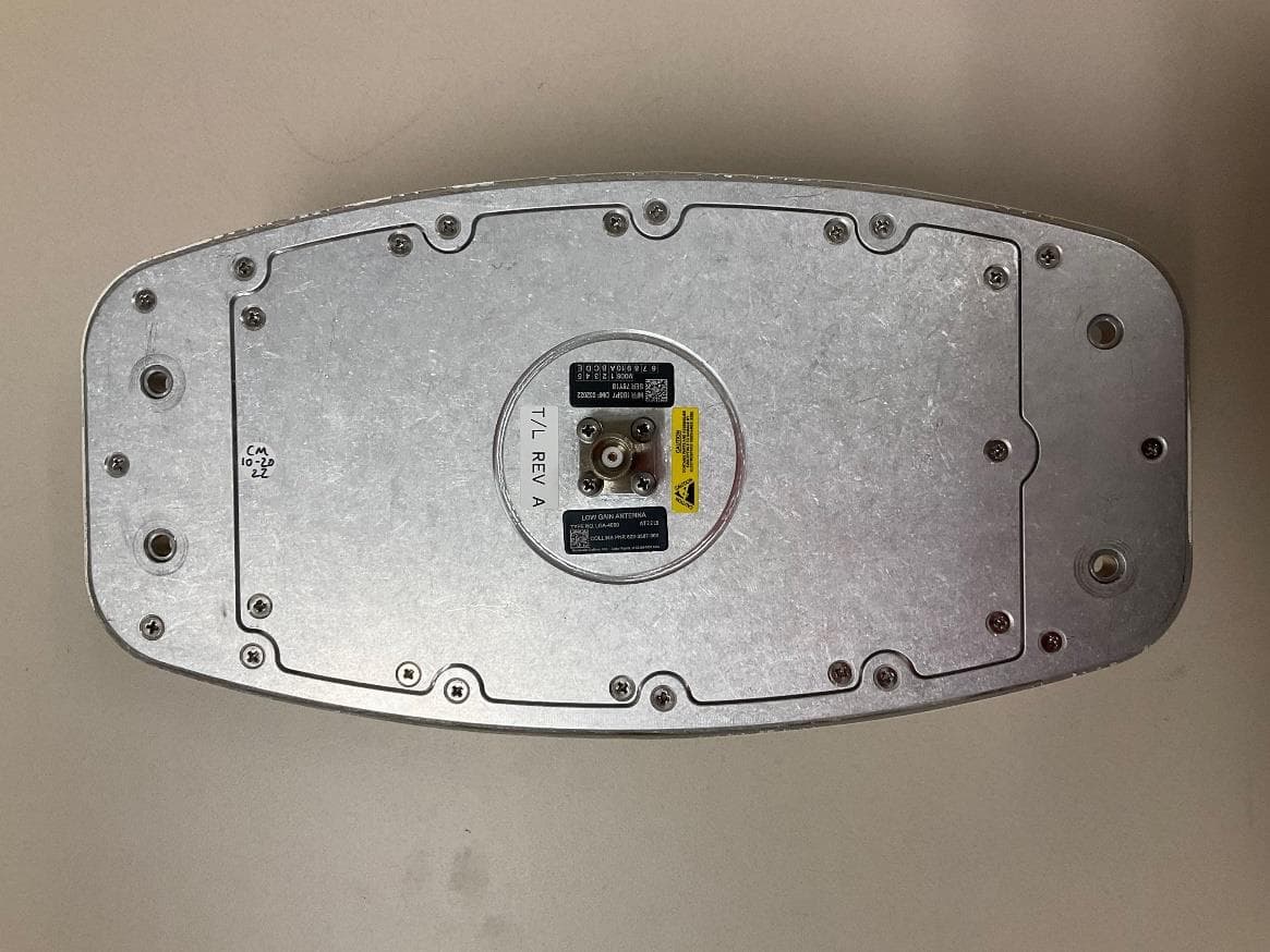
AJK8223587
Jan 23, 2023IRT-4200 SATCOM System
Equipment Class
TNB - Licensed Non-Broadcast Station Transmitter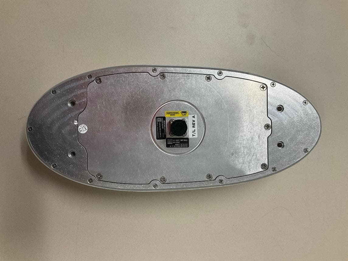
AJK8223586
Jan 23, 2023IRT-4400 SATCOM System
Equipment Class
TNB - Licensed Non-Broadcast Station Transmitter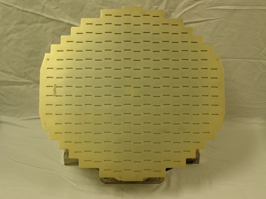
AJK8222259
Nov 11, 2015Weather Radar
Equipment Class
TNB - Licensed Non-Broadcast Station Transmitter
AJK8223132
May 20, 2015Information Management System
Equipment Class
DTS - Digital Transmission System
AJK8223075
Mar 04, 2013TCAS II Transmitter/Receiver
Equipment Class
TNB - Licensed Non-Broadcast Station Transmitter