AJK8221468Dual Channel Spacing Aeronautical Transceiver
Rockwell Collins Inc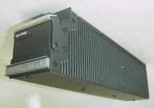
Click to zoom
Application Details
- Equipment Class
- TNB - Licensed Non-Broadcast Station Transmitter
- Date of Grant
- Mar 06, 2002
- Application Purpose
- Original Equipment
- Date of Application
- Oct 17, 2001
- Equipment Note
- Dual Channel Spacing Aeronautical Transceiver
- Frequency Range
- 118.00000000 - 136.99167000
- Company
- Rockwell Collins Inc
- Country
- United States
Documents & Files
Document Text
Text extracted from the exhibit documents filed with the FCC. Open a document above to read the original.
Users Manual
USER’S MANUALS – EXHIBIT H 1.1 MANUALS Rockwell Collins, Inc. does not supply an instruction book with the VHF-4000 transceiver. The transceiver is supplied to airframe manufacturers and airlines, and designed to meet the requirements of ARINC 716-8 and ARINC 750. Operating instructions are not necessary because the unit is part of a larger VHF communications system. Rockwell Collins does produce the VHF- 4000 Component Maintenance Manual, a comprehensive installation manual which, pursuant to an agreement with the FCC staff, is available upon request but in not included in this electronic exhibit.
Cover Letter(s)
Washington O ffice December 14, 2001 Ms. Linda Elliott Federal Communications Commission 445 12 th Street, SW Washington DC, 20554 RE: Administrative Update Dear Ms. Elliott, Rockwell Collins, Inc. would like to administratively update the FCC ID for our equipment certification application (FCC Confirmation Number: EA102774). Rockwell Collins would like the FCC ID to be: AJL822-1468. In our application the FCC ID and resultant file number is currently: AJK822-1468. Rockwell Collins would like to make the FCC ID (and file number for computer access to the filing system) the following: AJL822-1468 . Thank you for correcting the file. If you have any questions or require any additional information, please do not hesitate to contact me via e-mail or at 703-516-8213. Sincerely, Joseph Cramer
Cover Letter(s)
Washington O ffice December 21, 2001 Mr. Richard Fabina Office of Engineering and Technology Laboratory Federal Communications Commission 7435 Oakland Mills Rd Columbia MD 21046-1609 RE: Administrative Update Dear Mr. Fabina, Thank you for taking the time to speak with me today regarding our equipment certification application for the VHF-4000 (FCC ID: AJK822-1468). As stated in our conversation, Rockwell Collins would like to administratively update the FCC ID to: AJL8221468 with the corresponding FCC Confirmation Number: EA102774. Please disregard and delete from the system the cover letter (Administrative Update) dated December 14, 2001. Rockwell Collins would like the FCC ID to be: AJL8221648. In our application, the FCC ID and resultant file number is currently: AJK822-1648. Changing the FCC ID in the computer will make the FCC ID correspond to the FCC ID submitted in the ID Label and Location Information attachment filed on October 19, 2001. Thank you for assistance. If you have any questions or require any additional information, please do not hesitate to contact me via e-mail or at 703-516-8213. Sincerely, Joseph Cramer
Cover Letter(s)
FEE. 12.200212: 15AM HO FAA ASR 1 NO.~53P.2 800 Independence Ave.. S.w. Washir\Qtcn. DC 20591 3 200? JAN Mr. Frank Coperich Federal Communications Commission Equipment Authorization Branch 7435 Oakland Mills Road Columbia, Maryland 21046 Dear Mr Coperich: We have reviewed the request from Rockwell Collins for Type Acceptance of the VHF-4000 Communications Transceiver. The Federal Communications Commission ID number is AJL6221468. Our Office has reviewed the technical data for this transceiver and the equipment's performance is consistent with the spectrum requirements of. Technical Specification Order C37e. We have no objection to the certification of this device. If you require anyadditional information, please contact Ms. Margarette Ebate, Spectrum Planning and International Division, at (202) 493-5195. us. Depo~r of TtansportoTion Federal Aviation Admlnl,tratlon Do~ld K. willis Acting Deputy Program Director for SpectrumPolicy and Management
Cover Letter(s)
October 19, 2001 Federal Aviation Administration Mr. George Sakai, ASR-1 Program Director Spectrum Engineering Division 800 Independence Avenue, SW Room 715 Washington, DC 20591 Re: FAA Notification of FCC Equipment Approval Under FCC Part 87 VHF- 4000 Communications Transceiver Mr. Sakai: In accordance with the requirements of the Federal Communications Commission Rules and Regulations, Part 87.147(d), Rockwell Collins, Inc. hereby notifies the Federal Aviation Administration of its simultaneous filing with the FCC of an application for type acceptance on FCC Form 731 of equipment intended for transmission in frequency ranges set forth in FCC rules Part 87.147(d)(3) which require FAA notification. The application for type acceptance covers Rockwell Collins VHF-4000 Communications Transceiver. One complete set of the filing documents is enclosed, including a copy of Form 731, a detailed product description and test data for the VHF-4000. Please direct any questions regarding this filing to Joe Cramer, (703)516-8213. Respectfully submitted, Maggie O’Neill Administrative Assistant Governmental & Regulatory Affairs cc: Federal Communications Commission
External Photos
Exhibit C. External Photos Index of Photos Photo Placement.Description Top LeftExternal View from Front Left Top RightExternal View from Front Right Bottom LeftExternal View from Rear Bottom CenterExternal View from Front Bottom Right Nameplate Placement
ID Label/Location Info
ID LABEL/LOCATION INFORMATION – EXHIBIT A 1. NAME PLATE The nameplate appears on the front of the transceiver. A picture of the nameplate installation is shown in Exhibit C. A drawing of the nameplate is shown below.
ID Label/Location Info
A SIZE 4V792 CAGE DWG NO REV LTR SCALE 2/1 SHEET FOR REVISION CENTER USE ONLY: REVISION NO. DCN SHEET NO. 829–0402 3 NOTE: FABRICATE IN ACCORDANCE WITH 628–9000–001. NOTE COPIES OF THIS DRAWING UNLESS ON STABLE BASED MAT’L ARE FOR REFERENCE ONLY UNLESS OTHERWISE SPECIFIED DIMENSIONS ARE IN INCHES TOL ON DIMENSIONS DIM .XX = +/– 0.02 HOLE DIA = +/– 0.005 PART SHALL COMPLY TO 580–5800–001 829–0402–002 TYPE NO. VHF–4000 TRANSCEIVER, VHF COMM DO–160D ENV CAT. 822–1468– WT LB S/N Rockwell Collins, Inc. Cedar Rapids, IA 52498 USA/Mfd Melbourne, FL 1.60 .80 FAA TSO C37d, C38d, C128 DO–178B LEVELS C/D 200 NM, 25 KHZ FCC ID: AJK8221468 12345678910111213141516 17181920212223242526ABCDEF MOD 200NM, 8.33 KHZ
Internal Photos
Exhibit I. Internal Photographs Photo 1: DSP/Power Supply Circuit Card, Top View Photo 2: DSP/Power Supply Circuit Card, Bottom View Photo 3: RF Circuit Card, Top View Photo 4: RF Circuit Card, Bottom View Photo 5: Rear Interconnect Circuit Card, Top View Photo 6: Assembled VHF-4000, with cover removed. View of DSP/Power Supply Circuit Card side Photo 7: Open Chassis view of VHF-4000 showing RF card assembly on the right, interconnections, and chassis web under DSP/Power Supply. The Connectorized component at middle right is a lowpass filter in both receive and transmit paths. See circuit description, exhibit L. Photo 8: View of RF Circuit Card in shielded assembly. Photo 9: View of RF Circuit Card Assembly, showing placement of shield walls.
Operational Description
OPERATIONAL DESCRIPTION – EXHIBIT L 1.1 GENERAL DESCRIPTION OF CIRCUITRY The VHF-4000 consists of 3 sub-assemblies; A1 VHF RF Assembly, A2 Signal Processor/Power Supply Assembly, and A3 Rear Interconnect Assembly. The VHF-4000 power amplifier linearly amplifies the transmitter synthesizer output to a 16 watt (minimum) carrier power level for AM voice or analog data operation. The power output in VDL Mode 2 is a minimum of 15 watts. Voice, analog data, or digital data is impressed on the input RF from the synthesizer in a vector (I-Q) modulator, used as a variable RF attenuator and phase modulator. A synchronous detector sampling the RF power output provides amplitude and phase (I-Q) feedback information to the vector modulator to linearize the amplitude and phase characteristics of the power amplifier, and to maintain power output in varying environmental conditions. A low pass filter at the output attenuates the transmitter harmonics to a level at least 60 dB below the carrier level. The VHF-4000 receiver utilizes a single conversion design. The receiver synthesizer LO (high side injection) is applied to the first mixer, generating a 28.875 MHz first IF frequency w hich is amplified and then detected by use of DSP technology. For voice operation, a noise quieting squelch and carrier squelch is provided. For receive operation, the VHF-4000 frequency synthesizer is a single loop, TCXO reference- controlled design and provides the receive LO for any 25 kHz or 8.33 kHz channel selected in the 118.000 to 136.992 MHz frequency range. (Note that by definition, 8.33 kHz = 25 kHz/3, and all references to these frequencies can be written to one Hz). A second, dedicated frequency synthesizer is used for transmit operation. It is a single loop, TCXO reference-controlled design and provides the direct transmit frequency RF drive for any 25 kHz or 8.33 kHz channel selected in the 118.000 to 136.992 MHz frequency range to the vector modulator and RF power amplifier. Both receive and transmit frequency synthesizers use a common 23.1 MHz +/- 5 PPM temperature compensated crystal oscillator (TCXO) as the reference. The +/- 5 PPM tolerance includes the effects of aging for up to 10 years of operation. There are no operator adjustments for power level, microphone gain, audio compression, or other transmitter parameters. The operator controls (provided by a separate assembly) are for frequency selection and receiver audio gain (volume). 1.2 TYPES OF EMISSIONS When 25 kHz AM operation is selected, voice or analog data modes are enabled. The types of emissions on 25 kHz analog channels are: 5K00A3E and 10K00A3D When 8.33 kHz AM operation is selected, only voice is enabled. The type of emission on 8.33 kHz analog channels is: 5K00A3E When 25 kHz channel VDL Mode 2 operation is selected, the digital data mode is enabled. The transmit waveform is a 31.5 Kb/sec D8PSK signal using raised cosine filtering with excess bandwidth of 0.6. The type of emission on 25 kHz digital data channels is: 14K0G1DE 1.3 FREQUENCY RANGE Frequency range: 118.000 through 136.975 MHz (including two 8.33 kHz channels at 136.983333 and 136.991666 KHz) 1.4 OPERATING POWER AM voice and analog data modes - 18 watts carrier power (not adjustable by operator) Minimum carrier power is 16 watts under any single aircraft normal environmental condition, to satisfy the requirements of airworthiness authorities. VDL Mode 2 – 18 watts average power (not adjustable by operator) Minimum average power is 15 watts under any single aircraft normal environmental condition, to satisfy the requirements of airworthiness authorities. 1.5 MAXIMUM POWER RATING Part 87 of the FCC Rules and Regulations, Section 87.131, defines a maximum power rating of 55 watts for an Aircraft (Communication) Class of station. The VHF-4000 does not exceed this limitation. 1.6 DC VOLTAGES AND CURRENTS The DC voltage applied to the drains of the final transistors is 27.5 VDC (nominal). With an un- modulated carrier, the DC current into the final amplifier stage typically total 4 amperes in voice and analog data modes. In VDL Mode 2, the modulated DC current into the final amplifier stages typically totals 3.7 amperes. The sources of A1Q906 and A1Q903 (the power output stages) are grounded. 1.7 CIRCUITRY FOR SUPPRESSION OF SPURIOUS RADIATION The low-pass filter suppresses transmitter spurious radiator. This is located on the A1 RF Assembly and shown on schematic 828-3186-002. An additional low pass filter, common to both transmit and receive functions is in the common antenna cable from the unit. This filter provides additional filtering for transmitter harmonics through the 1.5 GHz GPS band. 1.8 CIRCUITRY FOR LIMITING MODULATION Modulation limiting is achieved in the audio compressor that is implemented in software on the A2 Signal Processor. As the compressor characteristic curves in this report show, this compressor circuit operates as a linear amplifier until the input signal reaches such level that the software begins to reduce the gain by mathematically scaling the internal digitally processed signal. The large dynamic range above the compression knee minimizes the possibility of over-modulation. This guarantees that the RF output cannot go to zero, even during severe overdrive of the audio inp ut to the co mpressor. 1.9 CIRCUITRY FOR LIMITING POWER The carrier power output is controlled by adjusting the DC component of the audio signal applied to the modulator controller, A1U800 on the RF assembly, 828-3186-002. This DC level is a service adjustment, not accessible to the operator. The VHF-4000 contains circuitry on the RF assembly that prevents excessive power output with changes in operating conditions, with the use of an automatic feedback control system. No user accessible controls are employed. A software controlled reduction of peak power occurs during times of low power supply voltage (less than 22.0 VDC) so to prevent distortion of the positive modulation peaks. This …
Text truncated - open the document above for the full version.
Parts List/Tune Up Info
PARTS LIST/TUNE-UP INFORMATION – EXHIBIT J 1.1 PARTS LIST DescriptionAssembly A1 RF Assembly CardSee Attachment 828-3186-002 A2 Signal Processor/Power Supply Card See Attachment 828-3187-002 A3 Rear Interconnect See Attachment 828-3185-002 1.2 TUNE UP PROCEDURE Alignment procedures are included in the draft Production Test Requirement (PTR) attached to this report as PTR. Both the FCC and the Federal Aviation Administration intend these procedures for use only by factory personnel or by avionics repairmen. The only transmitter control available to the equipment operator (the aircraft pilot or other flight crewmember) is selection of the operati ng freq ue nc y c hannel.
Schematics
SCHEMATIC – EXHIBIT E 1.1 SCHEMATICS DescriptionSchematic A1 RF Assembly CardSee Attachment RF Circuit Card Assembly Schematic.pdf A2 Signal Processor/Power Supply CardSee Attachment DSP_Power Supply Schematic.pdf A3 Rear InterconnectSee Attachment – Rear Interconnect Schematic.pdf
Test Report
TEST REPORT – EXHIBIT F PART 1 1. TRANSMITTER PERFORMANCE TESTS – EXHIBIT I This section documents the test procedures used, and records the results of tests to demonstrate compliance with the applicable requirements of parts 2 and 87 of the FC Rules and Regulations. 1.1 RF POWER OUTPUT 1.1.1 REQUIREMENTS FCC Sec. 2.1046 Measurements required: RF power output. (a) For transmitters other than single sideband, independent sideband and controlled carrier radiotelephone, power output shall be measured at the RF output terminals when the transmitter is adjusted in accordance with the tune-up procedure to give the values of current and voltage on the circuit elements specified in Sec. 2.1033(c)(8). The electrical characteristics of the radio frequency load attached to the output terminals when this test is made shall be stated. FCC 87.131 Power must be determined by direct measurement. The following lists authorized emissions and maximum power. Class of StationFrequency Band EmissionsPower Aircraft (Communications)VHFA3E, A9W55 w The power is measured at the transmitter output terminals and the type of power is determined according to the emission designator as follows: Mean power (pY) for amplitude modulated emissions and transmitting both sidebands using unmodulated full carrier. Power is restricted to the minimum necessary to achieve the required service. 1.1.2 TEST PROCEDURE The VHF-4000 was adjusted in accordance with the tune-up instructions. Primary power supply was set to 27.5 VDC. Unmodulated carrier power was measured at carrier frequency intervals beginning at 118.000 MHz. The RF load for these measurements was a 30 dB attenuator with an HP435B Power Meter. The characteristics of the attenuator and Power Meter were measured with an HP8753C network analyzer and 856046A S-Parameter test set. A table of VSWR values taken vs. frequency from 118 to 137 MHz follows the power data, and shows that the load is essentially 50 ohms resistive over this frequency range. 1.1.3 TEST RESULTS The first data sheet that follows is the VHF-4000 in AM mode and shows power measurements across the band covered by this transmitter. The power level is the same for 25 kHz channels as it is for 8.33 kHz channels. Part 87 of the FCC Rules does not define a maximum authorized power. The measured power output is typical of that provided in VHF transceivers for commercial aircraft. The second data sheet which follows is the VHF-4000 in digital data VDL Mode 2 and shows power measurements across the band covered by this transmitter. The measured power output is typical of that provided in VHF transceivers for commercial aircraft for VDL Mode 2 operations. 1.1.4 POWER OUTPUT DATA SHEET Type Number:VHF-4000Serial Number:FBLF Date Tested:09/14/01Tested by:Je rry Che twynd Freque ncy TX Power Output 118.000 MHz 20Watts 122.000 MHz 18Watts 125.000 MHz 18Watts 129.000 MHz 18Watts 131.000 MHz 18Watts 133.000 MHz 17.5Watts 136.975 MHz 17.5Watts Type Number:VHF-4000 VDL MODE 2Serial Number:FBLF Date Tested:9/25/01Tested by:Bob Lombardi Freque ncy ( MH z) TX Power Output 118.000 20.32 Watts 122.000 20.18 Watts 125.000 21.09 Watts 129.000 20.70 Watts 131.000 22.70 Watts 133.000 22.34 Watts 136.975 24.77 Watts 1.1.5 RF LOAD CHARACTERISTICS Fre que ncy ( MHz )R F Loa d VS WR 118.0001.03:1 122.0001.03:1 125.0001.03:1 129.0001.03:1 131.0001.03:1 133.0001.03:1 137.0001.03:1 1.2 MODULATION CHARACTERISTICS 1.2.1 REQUIREMENTS FCC Sec. 2.1047 Measurements required: Modulation characteristics. (a) Voice modulated communication equipment. A curve or equivalent data showing the frequency response of the audio modulating circuit over a range of 100 to 5000 Hz shall be submitted. For equipment required to have an audio low-pass filter, a curve showing the frequency response of the filter, or of all circuitry installed between the modulation limiter and the modulated stage shall be submitted. (b) Equipment w hich employs modulation limiting. A curve or family of curves showing the percentage of modulation versus the modulation input voltage shall be supplied. The information submitted shall be sufficient to show modulation limiting capability throughout the range of modulating frequencies and input modulating signal levels employed. FCC Sec. 87.141 Modulation requirements. (a) When A3E emission is used, the modulation percentage must not exceed 100 percent. This requirement does not apply to emergency locator transmitters or survival craft transmitters. (b) A double sideband full carrier amplitude modulated radiotelephone transmitter with rated carrier power output exceeding 10 watts must be capable of automatically preventing modulation in excess of 100 percent. 1.2.2 TEST PROCEDURE Frequency Response Data The audio generator is set to 1000 Hz, and its level adjusted to 0.25 Vrms. The transmitter modulation was adjusted to produce 90% modulation on the 25 kHz channels and on the 8.33 kHz channels. While maintaining this input level, the modulation depth is recorded over the frequency range of 100 Hz to 5000 Hz. Compression Characteristic Data Next, with audio generator set to 1000 Hz, the modulation depth was recorded for audio generator output levels over the range of 10 mVrms to 1.0 Vrms. This procedure was repeated at modulating frequencies of 100 Hz, 350 Hz, 2500 Hz, and 5000 Hz. 1.2.3 TEST RESULTS The data following represents the results of these measurements of modulation frequency response and compressor limiting characteristics on the VHF-4000. Type Number:VHF-4000 Serial Number:FBLF Date Tested:Tested by:Je rry Che twynd Frequency Response Data 25 kHz Channel, 126.500 MHz8.33 kHz Channel, 126.500 MHz Freque ncy (Hz) Mod ulation Depth (%) Relative Response (dB) Mod ulation Depth (%) Relative Response (dB) 10010.2-18.9110.7-19.3 35074.0-1.7073-1.7 60088.0-0.2082.2-0.6 100090.00.0090.00 150090.20.0285-0.3 200088.5-0.1584-0.5 250082.0-0.8177.5-1.2 300063.0-3.107.0-22 400021.2-12.56.5-52 50007.3-21.82.5-52 Compression Characteristic …
Text truncated - open the document above for the full version.
Test Report
TEST REPORT PART 2– EXHIBIT F
Test Report
TEST REPORT PART 3– EXHIBIT F 1. FAA NOTIFICATION - EXHIBIT J Provided by Rockwell Collins Governmental and Regulatory Affairs Department 2. SPURIOUS RADIATION MEASURMENT REPORT – (SEE EXHIBIT K)
Test Report
284 West Drive, Suite B Melbourne, FL 32904 RUBICOM SYSTEMS, INC. SEPTEMBER 2001 Rubicom Systems, Inc. THIS REPORT SHALL NOT BE REPRODUCED EXCEPT IN FULL WITHOUT THE WRITTEN APPROVAL OF THE TESTING LABORATORY FCC TEST REPORT (INTENTIONAL RADIATOR) FOR THE ROCKWELL COLLINS, INC. VHF-4000 COMMUNICATIONS TRANSCEIVER (118-137MHz) JA-1855 1 FCC TEST REPORT (INTENTIONAL RADIATOR) FOR THE ROCKWELL COLLINS, INC. VHF-4000 COMMUNICATIONS TRANSCEIVER (118-137MHz) S/N: FBLF PART 1 Prepared by: __________________________________________ Joseph G. Barbee Tested by:__________________________________________ Alex Belardinelli Performed by:Performed for: RUBICOM SYSTEMS, INC.ROCKWELL COLLINS, INC. 284 West Drive, Suite B1100 W. Hibiscus Blvd. Melbourne, Florida 32904Melbourne, Florida 32901 Received:September 9, 2001 Completed:September 12, 2001 JA-1855 2 TABLE OF CONTENTS ParagraphTitle Page ABST RACT ............................................................................................................. 3 1.0INTRODUCTION ..................................................................................................... 4 1.1Purpose ................................................................................................................... 4 1.2Requirements .......................................................................................................... 4 1.3Equipment Under Test Description ......................................................................... 5 1.4Summary of Results ................................................................................................ 5 2.0APPLICABLE DOCUMENTS ................................................................................. 6 3.0TEST SITE DESCRIPTION .................................................................................... 7 3.1Enviro nmental Conditio ns ....................................................................................... 7 4.0TEST INSTRUMENTATION ................................................................................... 8 5.0TEST SAMPLE SETUP AND CONFIGURATION ................................................. 9 6.0PROCEDURES AND RESULTS .......................................................................... 11 6.1Radiated Emissions (Receive Mode).................................................................... 11 6.2Spurio us Emissions (TX Mode) ............................................................................ 11 APPENDIX A COMPLIANCE LETTER ....................................................................................... 35 JA-1855 3 ABST RACT This report presents test results of emanations found emitting from the Rockwell Collins VHF-4000 and the compariso n of these emissions to the requirements of FCC, Title 47, Part 15, Subpart C for spurio us radiated emissions. This testing was performed on a 3 meter open area test site at Rubicom Systems, Inc. (RSI). The testing was performed for Rockwell Collins, Inc. under purchase order 4500525371 and is filed under JA-1855 at RSI. The results of this test effort demonstrate compliance of the Rockwell Collins, VHF-4000 to FCC, Title 47, Part 15, Subpart C intentional radiators. Equipment under test (EUT) was a Rockwell Collins VHF-4000 Transceiver, s/n: FBLF. JA-1855 4 1.0INTRODUCTION 1.1Purpose The purpose of this report is to show compliance of the Rockwell Collins, Inc. Model VHF-4000 to the requirements of Part 15 of the FCC Rules and Regulations (47CFR, Part 15, Subpart C) for intentio nal radiators. The tests were performed on a 3 meter site. 1.2Requirements The test requirements are as follo ws: RADIATED RX MODE (15.209A) Frequency (MHz) 3 Meter Field Strength (μV/m) 3 Meter (dBμV/m) 30 - 8810040 88 - 21615043.5 216 - 96020046 960 - Above50054 Avg. 74 Peak CONDUCTED TX MODE (CFR 87.139) Harmonics of transmitter attenuated by at least 43dB. This test was performed as a co nducted test o n the antenna port up to the 10 th harmonic. No signals appear at the antenna port other than the intended transmit signal. JA-1855 5 1.3Equipment Under Test The VHF-4000 Transceiver is a solid state, 2280 channel AM transceiver designed to provide air to air or air to ground voice or data communications in the 118.000 to 136.975MHz VHF band. It operates in communicatio ns systems having 25KHz or 8.33KHz channel spacing. The unit operates o n 27.5 VDC and is packaged for use in co nfigurations that do not use ARINC standard packages. Power output is 20 watt carrier power. A low pass filter at the output attenuates transmitter harmonics of at least 60dB below the carrier level. This report reflects the transceiver status after “Red Label Mod. #16” was installed. 1.4Summary of Results Results are presented in Paragraph 6.0. The VHF-4000 meets the requirements stated in Paragraph 1.2. JA-1855 6 2.0APPLICABLE DOCUMENTS The following documents form a part of this report to the extent expressed he rei n: FCC Code of Federal Regulations Title 47, Part 15 FCC Procedure for Measuring RF Emissions from Computing Devices FCC/OET MP-4, July 1987 ANSI C63.4-1992 FCC Characteristics of Open Field Test Sites Bulletin OET 55, October 1989 JA-1855 7 3.0TEST SITE DESCRIPTION This testing was performed at Rubicom Systems, Inc. 3 meter open area test site. The descriptio n of the measurement facility was found to be compliant with the requirements of Section 2.948 of the FCC rules. A copy of the compliance letter is attached to this report as Appendix A. 3.1Environmental Conditions Enviro nmental conditio ns during testing of the EUT were as follows: Date: September 11, 2001 Temperature: 88º Barometer: 29.35 inches Humidity: 80% JA-1855 8 4.0TEST INSTRUMENTATION The following test equipment was used to perform this testing. Qty.DescriptionManufacturerModel No.Last Cal.Cal. Cycle 1Spectrum AnalyzerAdvantestR327101/18/011 Yr. 1BiLog AntennaChaseCLB6111B07/17/011 Yr. 1AmplifierHewlett Packard8449B05/01/011 Yr. 1Ridge Guide HornA.H. SystemsSAS-20…
Text truncated - open the document above for the full version.
Test Report
284 West Drive, Suite B Melbourne, FL 32904 RUBICOM SYSTEMS, INC. SEPTEMBER 2001 Rubicom Systems, Inc. THIS REPORT SHALL NOT BE REPRODUCED EXCEPT IN FULL WITHOUT THE WRITTEN APPROVAL OF THE TESTING LABORATORY FCC TEST REPORT (INTENTIONAL RADIATOR) FOR THE ROCKWELL COLLINS, INC. VHF-4000 COMMUNICATIONS TRANSCEIVER (118-137MHz) JA-1855 1 FCC TEST REPORT (INTENTIONAL RADIATOR) FOR THE ROCKWELL COLLINS, INC. VHF-4000 COMMUNICATIONS TRANSCEIVER (118-137MHz) S/N: FBLF PART 2 Prepared by: __________________________________________ Joseph G. Barbee Tested by:__________________________________________ Alex Belardinelli Performed by:Performed for: RUBICOM SYSTEMS, INC.ROCKWELL COLLINS, INC. 284 West Drive, Suite B1100 W. Hibiscus Blvd. Melbourne, Florida 32904Melbourne, Florida 32901 Received:September 9, 2001 Completed:September 12, 2001 JA-1855 2 DATA SHEET 6.1-4 JA-1855 3 DATA SHEET 6.1-5 JA-1855 4 DATA SHEET 6.1-6
Test Report
284 West Drive, Suite B Melbourne, FL 32904 RUBICOM SYSTEMS, INC. SEPTEMBER 2001 Rubicom Systems, Inc. THIS REPORT SHALL NOT BE REPRODUCED EXCEPT IN FULL WITHOUT THE WRITTEN APPROVAL OF THE TESTING LABORATORY FCC TEST REPORT (INTENTIONAL RADIATOR) FOR THE ROCKWELL COLLINS, INC. VHF-4000 COMMUNICATIONS TRANSCEIVER (118-137MHz) JA-1855 1 FCC TEST REPORT (INTENTIONAL RADIATOR) FOR THE ROCKWELL COLLINS, INC. VHF-4000 COMMUNICATIONS TRANSCEIVER (118-137MHz) S/N: FBLF PART 3 Prepared by: __________________________________________ Joseph G. Barbee Tested by:__________________________________________ Alex Belardinelli Performed by:Performed for: RUBICOM SYSTEMS, INC.ROCKWELL COLLINS, INC. 284 West Drive, Suite B1100 W. Hibiscus Blvd. Melbourne, Florida 32904Melbourne, Florida 32901 Received:September 9, 2001 Completed:September 12, 2001 JA-1855 2 DATA SHEET 6.1-7 JA-1855 3 DATA SHEET 6.1-8 JA-1855 4 DATA SHEET 6.1-9
Test Report
284 West Drive, Suite B Melbourne, FL 32904 RUBICOM SYSTEMS, INC. SEPTEMBER 2001 Rubicom Systems, Inc. THIS REPORT SHALL NOT BE REPRODUCED EXCEPT IN FULL WITHOUT THE WRITTEN APPROVAL OF THE TESTING LABORATORY FCC TEST REPORT (INTENTIONAL RADIATOR) FOR THE ROCKWELL COLLINS, INC. VHF-4000 COMMUNICATIONS TRANSCEIVER (118-137MHz) JA-1855 1 FCC TEST REPORT (INTENTIONAL RADIATOR) FOR THE ROCKWELL COLLINS, INC. VHF-4000 COMMUNICATIONS TRANSCEIVER (118-137MHz) S/N: FBLF PART 4 Prepared by: __________________________________________ Joseph G. Barbee Tested by:__________________________________________ Alex Belardinelli Performed by:Performed for: RUBICOM SYSTEMS, INC.ROCKWELL COLLINS, INC. 284 West Drive, Suite B1100 W. Hibiscus Blvd. Melbourne, Florida 32904Melbourne, Florida 32901 Received:September 9, 2001 Completed:September 12, 2001 JA-1855 2 DATA SHEET 6.1-10 JA-1855 3 DATA SHEET 6.1-11 JA-1855 4 DATA SHEET 6.1-12
Test Report
284 West Drive, Suite B Melbourne, FL 32904 RUBICOM SYSTEMS, INC. SEPTEMBER 2001 Rubicom Systems, Inc. THIS REPORT SHALL NOT BE REPRODUCED EXCEPT IN FULL WITHOUT THE WRITTEN APPROVAL OF THE TESTING LABORATORY FCC TEST REPORT (INTENTIONAL RADIATOR) FOR THE ROCKWELL COLLINS, INC. VHF-4000 COMMUNICATIONS TRANSCEIVER (118-137MHz) JA-1855 1 FCC TEST REPORT (INTENTIONAL RADIATOR) FOR THE ROCKWELL COLLINS, INC. VHF-4000 COMMUNICATIONS TRANSCEIVER (118-137MHz) S/N: FBLF PART 5 Prepared by: __________________________________________ Joseph G. Barbee Tested by:__________________________________________ Alex Belardinelli Performed by:Performed for: RUBICOM SYSTEMS, INC.ROCKWELL COLLINS, INC. 284 West Drive, Suite B1100 W. Hibiscus Blvd. Melbourne, Florida 32904Melbourne, Florida 32901 Received:September 9, 2001 Completed:September 12, 2001 JA-1855 2 DATA SHEET 6.1-13 JA-1855 3 DATA SHEET 6.1-14 JA-1855 4 DATA SHEET 6.1-15
Test Report
284 West Drive, Suite B Melbourne, FL 32904 RUBICOM SYSTEMS, INC. SEPTEMBER 2001 Rubicom Systems, Inc. THIS REPORT SHALL NOT BE REPRODUCED EXCEPT IN FULL WITHOUT THE WRITTEN APPROVAL OF THE TESTING LABORATORY FCC TEST REPORT (INTENTIONAL RADIATOR) FOR THE ROCKWELL COLLINS, INC. VHF-4000 COMMUNICATIONS TRANSCEIVER (118-137MHz) JA-1855 1 FCC TEST REPORT (INTENTIONAL RADIATOR) FOR THE ROCKWELL COLLINS, INC. VHF-4000 COMMUNICATIONS TRANSCEIVER (118-137MHz) S/N: FBLF PART 6 Prepared by: ________________________________________…
Text truncated - open the document above for the full version.
Contact Information
Applicant
Thomas A. Voltero(Senior Counsel)
Technical Contact
Rockwell Collins, Inc.Joseph Cramer
[email protected]703-516-8213
1300 Wilson Blvd. · Arlington, Virginia · United States
Non-Technical Contact
Rockwell Collins, Inc.Joseph Cramer
[email protected]703-516-8213
Test Firm
Advanced Compliance Solutions, Inc.Sam Wismer
Technical Specifications
| # | Rule Parts | Frequency Range | Power Output | Emission | Tolerance |
|---|---|---|---|---|---|
| 3 | 87 | 118 MHz - 136.99167 MHz | 20 W | 5K00A3E | 5 ppm |
Other Applications from Rockwell Collins Inc
AJK8223587
Jan 23, 2023IRT-4200 SATCOM System
Equipment Class
TNB - Licensed Non-Broadcast Station Transmitter
AJK8223586
Jan 23, 2023IRT-4400 SATCOM System
Equipment Class
TNB - Licensed Non-Broadcast Station Transmitter
AJK8222259
Nov 11, 2015Weather Radar
Equipment Class
TNB - Licensed Non-Broadcast Station Transmitter
AJK8223132
May 20, 2015Information Management System
Equipment Class
DTS - Digital Transmission System
AJK8223075
Mar 04, 2013TCAS II Transmitter/Receiver
Equipment Class
TNB - Licensed Non-Broadcast Station Transmitter