AJK8221710WRT-2100 MultiScan Weather Radar Receiver/Transmit
Rockwell Collins Inc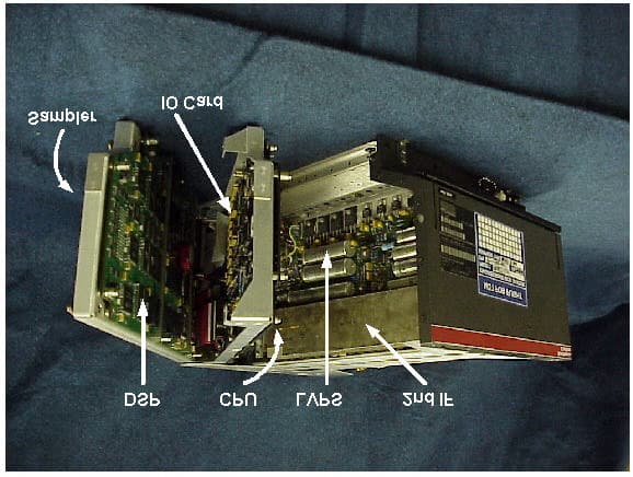
Click to zoom
Application Details
- Equipment Class
- TNB - Licensed Non-Broadcast Station Transmitter
- Date of Grant
- May 09, 2002
- Application Purpose
- Original Equipment
- Date of Application
- Mar 20, 2002
- Equipment Note
- WRT-2100 MultiScan Weather Radar Receiver/Transmit
- Frequency Range
- 9327.06400000 - 9338.87600000
- Company
- Rockwell Collins Inc
- Country
- United States
Documents & Files
Document Text
Text extracted from the exhibit documents filed with the FCC. Open a document above to read the original.
Attestation Statements
Exhibit 0-Attestation Statement CERT IFICAT E The WRT-2100 has been tested in accordance with the requirements contained in the appropriate Commission regulations. To the best of my knowledge, these tests were performed using measurement procedures consistent with industry or Commission standards and demonstrate that the WRT-2100 complies with the appropriate standards. Each unit manufactured, imported, or marketed, as defined in the Commission’s regulations, will conform to the sample(s) tested within the variations that can be expected due to quantity production and testing on a statistical basis. I hereby certify that the tests described in this report were performed at my direction and under my supervision, and that the results and test data contained in this report truly and accurately show the performance of the transmitter in the WRT-2100 transceiver. I further certify that the ancillary information contained herein accurately reflects the design, installation requirements, alignment procedures, and operational instructions of and for this transceiver. Signed. __ ______ Roy E. Robertson (Signature on Original File in the Cedar Rapids Certification Office)
Cover Letter(s)
CPN 815-3695-001 2002 Rockwell Collins, Inc. - All Rights ReservedPage 1 FCC Equipment Certification Application For WRT-2100 MultiScan Weather Radar Receiver/Transmitter CPN 815-3695-001 March 20, 2002 NOTICE : The contents of this document are proprietary to Rockwell Collins, Inc. and shall not be disclosed, disseminated, copied, or used except for purposes expressly authorized in writing by Rockwell Collins, Inc. exchanged. Rockwell Collins, Inc. Arlington, Virginia 22209, USA
Cover Letter(s)
CPN 815-3695-001 Rockwell Collins, Inc. - Proprietary InformationPage 1-1 Exhibit 1 – WRT-2100 Product Description CPN 815-3695-001 Rockwell Collins, Inc. - Proprietary InformationPage 1-2 Exhibit 1 – WRT-2100 Product Description TABLE OF CONTENTS 1.1System Overview .................................................................................................... 1-3 1.2System Components ............................................................................................... 1-4 1.3Aircraft Installation................................................................................................... 1-6 1.4Operation of Controls .............................................................................................. 1-7 1.5Equipment Specifications....................................................................................... 1-10 1.6Receiver-Transmitter............................................................................................. 1-12 1.7Source (A3A1) ...................................................................................................... 1-14 1.8Driver Module (A3) ................................................................................................ 1-18 1.9PA Module (A4).................................................................................................... 1-18 1.10Power Multiplier Module (A5) ............................................................................. 1-18 1.11Duplexer/Monitor(A6) ........................................................................................ 1-19 1.12Limiter/Preamplifier (A18) .................................................................................. 1-19 1.13Mixer/1 st IF Module (A7) .................................................................................... 1-20 1.14Second IF Module (A8)...................................................................................... 1-20 1.15Sampler Card (A31) .......................................................................................... 1-20 1.16DSP Card (A32) ................................................................................................ 1-20 1.17CPU Card (A34)................................................................................................ 1-21 1.18I/O Card (A33) .................................................................................................. 1-21 1.19Low Voltage Power Supply (A2)......................................................................... 1-21 1.20Rear Interconnect Module (A1) .......................................................................... 1-21 1.21Front Panel....................................................................................................... 1-21 1.22WRT-2100 Oscillators and Critical Frequencies................................................... 1-22 LIST OF FIGURES Figure 1-1. WRT-2100 System Components........................................................................ 1-5 Figure 1-2. Typical WXR-2100 Aircraft Installation................................................................ 1-6 Figure 1-3. WCP-702 Dual Control Panel............................................................................. 1-7 Figure 1-4. WRT-2100 Receiver-Transmitter Simplified Block Diagram................................ 1-12 Figure 1-5. WRT-2100 RF Section Block Diagram.............................................................. 1-13 Figure 1-6. Source Module (A3A1) .................................................................................... 1-14 LIST OF TABLES Table 1-1. DDS Source Frequencies ................................................................................. 1-16 Table 1-2. WRT-2100 Oscillators and Critical Frequencies.................................................. 1-22 CPN 815-3695-001 Rockwell Collins, Inc. - Proprietary InformationPage 1-3 1.1 System Overview The WRT-2100 MultiScan Weather Radar Receiver/Transmitter is an updated version of the Rockwell Collins WRT-701X Air Transport Weather Radar that has been in commercial service for over 20 years. The WRT-2100 is capable of Weather detection out to 320 nautical miles, Ground Mapping, Turbulence detection and Forward-Looking Windshear detection. In addition the WRT-2100 incorporates a new automatic operating mode called MultiScan. The purpose of MultiScan is to provide automatic superior weather hazard detection with an essentially clutter-free display to enable rapid pilot interpretation of weather hazards without the workload required for manual adjustment of the tilt control. Therefore, it is intended that the flight crew may turn on the MultiScan radar in AUTO mode prior to takeoff and fly the entire flight without use of the controls or adjustment of the radar. At the same time, however, if conditions warrant, all controls normally associated with radar operation - MODE, GAIN, and TILT, can be manually adjusted independently by the flight crew to enable a detailed assessment of the weather hazard or terrain situation. MultiScan operates by automatically scanning the antenna over multiple tilt settings while saving the individual scan data in memory. This internal memory data is continually refreshed and corrected for aircraft motion. The display to the flight crew is a composite of multiple scans which have been processed to remove ground clutter and provide an optimal display for weather detection. MultiScan utilizes advanced multiple beam ground clutter suppression techniques w hich allow the radar beams to be optimized for superior long and short range weather detection while at the same time eliminating clutter from the screen. These techniques enable rapid, unambiguous weather hazard interpretation without the workload associated with excessive tilt management. Ground clutter can be switched in or out of the display by using the Ground Clutter Suppression (GCS) switch. The Windshear Detection feature automatically a…
Text truncated - open the document above for the full version.
Cover Letter(s)
Washington Office 1300 Wilson Boulevard, Suite 200 Arlington, VA 22209-2307 703.516.8200 March 21, 2002 Federal Aviation Administration Spectrum Engineering Division ASR-200 800 Independence Avenue, SW Washington, DC 20591 Re: FAA Notification of FCC Equipment Approval Under FCC Part 87 WRT-2100 MultiScan Weather Radar Transmitter/Receiver FCC ID: AJK8221710 Gentle me n: In accordance with the Federal Communications Commission (FCC) Rules and Regulations, Part 87.147(d), Rockwell Collins, Inc. hereby notifies the Federal Aviation Administration (FAA) of its simultaneous filing with the FCC of an Application for Certification of the WRT-2100 MultiScan Weather Radar Transmitter/Receiver. One complete set of the filing documents is enclosed for your review. In addition, In accordance with the provisions of 47 CFR 0.459 and 0.457(d)(2)(I), Rockwell Collins, Inc. hereby request that Exhibit 4 - Tune Up Procedures, Exhibit 5 - Schematic Diagrams, and Exhibit 10 Parts Lists for the Equipment Certification for WRT-2100, MultiScan Weather Radar Receiver/Transmitter be withheld from public inspection. This application was electronically filed on March 20. 2002 and corresponds to FCC ID AJK8221710. Exhibits 4,5 and 10 contain confidential commercial information or technical data customarily guarded from competitors and is, therefore, exempt from disclosure under Exemption 4 of the Freedom of Information Act [5 USC 522(b)(4)] because disclosure could reasonably be expected to cause substantial competitive harm. Please direct any questions regarding this filing to Mr. Joe Cramer of this office on (703) 516- 8213 Respectfully submitted, Linda C. Sadler Director, Governmental & Regulatory Affairs cc: Federal Communications Commission
Cover Letter(s)
Washington Office 1300 Wilson Boulevard, Suite 200 Arlington, VA 22209-2307 March 21, 2002 Federal Communications Commission Office of Engineering and Technology Application Filed Via OET Laboratory Electronic Filing Site https://gullfoss.fcc.gov/prod/oet/index.html Re: Equipment Author ization Under Part 87 Certification WRT-2100 MultiScan Weather Radar Receiver/Transmitter FCC ID: AJK8221710 Gentle me n: Rockwell Collins, Inc. (Rockwell Collins) hereby submits an Application for Equipment Authorization for the WRT-2100 MultiScan Weather Radar Receiver/Transmitter (FCC ID: AJK8221710) using the Office of Engineering and Technology’s online filing system. One complete set of documents covering the WRT-2100, including a detailed product description and test data, is submitted as part of the Application. Rockwell Collins is sending another complete set of documents to the Federal Aviation Administration (FAA) pursuant to FCC Part 87.147(d). A copy of the transmittal letter to the FAA is enclosed as Exhibit 10. Your early consideration of the Application is respectfully requested. Please direct all inquiries to Mr. Joe Cramer of this office at (703) 516-8213. Respectfully submitted, Linda C. Sadler Director Governmental & Regulatory Affairs
Cover Letter(s)
Washington Office 1300 Wilson Boulevard, Suite 200 Arlington, VA 22209-2307 March 21, 2002 Federal Communications Commission Office of Engineering and Technology Application Filed Via OET Laboratory Electronic Filing Site https://gullfoss.fcc.gov/prod/oet/index.html Re: Equipment Authorization Under Part 87 Certification WRT-2100 MultiScan Weather Radar Receiver/Transmitter FCC ID: AJK8221710 Gentle me n: In accordance with the provisions of 47 CFR 0.459 and 0.457(d)(2)(I), Rockwell Collins, Inc. hereby request that Exhibit 4 - Tune Up Procedures, Exhibit 5 - Schematic Diagrams, and Exhibit 10 Parts Lists for Equipment Certification for WRT-2100 MultiScan Weather Radar Receiver/Transmitter be withheld from public inspection. This application was electronically filed on March 20. 2002 and corresponds to FCC ID AJK8221710. Exhibits 4, 5 and 10 contain confidential commercial information or technical data customarily guarded from competitors and is, therefore, exempt from disclosure under Exemption 4 of the Freedom of Information Act [5 USC 522(b)(4)] because disclosure could reasonably be expected to cause substantial competitive harm. Please note that Exhibits 5,8, 9 and 10 were broken into multiple electronic files in order to overcome technical difficulties in uploading to the OET Laboratory Electronic Filing Site. Your early consideration of the Application is respectfully requested. Please direct all inquiries to Mr. Joe Cramer of this office at (703) 516-8213. Respectfully submitted, Linda C. Sadler Director Governmental & Regulatory Affairs
Cover Letter(s)
800 Independence Ave" SW Washington, DC, 20591 u.s. Department of Transportation Federal Aviation Administration ~\ljl\? ? 6 200~ Mr. Handy Leimer Federal Communications Commission Equipment Authorization Branch 7435 Oakland Mills Road Columbia, Maryland 21046 Leirner:Dear Mr We have reviewed the request from Rockwell Collins for Type Acceptance of the WRT-2100 MultiScan Weather Radar Receiver/Transmitter. The Federal Communications Commission ID number is AJK8221710. We have no objection to the certification of this device. If you require any additional information, please contact Mr. Michael Biggs, Spectrum Planning and International Division, at (202) 267-8241. Sincerely, /) K. t'-- i Willis Manager, Spectrum Planning and International Division Rock\'lell Collins Washington Office 1300 Wilson Blvd, Suite 200 Arlington, VA 22209-2307
External Photos
CPN 815-3695-001 Rev -Rockwell Collins, Inc. - Proprietary InformationPage 7-1 Exhibit 7 – Equipment Photographs: External Views CPN 815-3695-001 Rev -Rockwell Collins, Inc. - Proprietary InformationPage 7-2 Exhibit 7 – Equipment Photographs: External Views ItemPhotograph DescriptionPage Figure 7-1 WXR-2100 Family 7-3 Figure 7-2 WFA-701 Flat Plate Antenna 7-4 Figure 7-3 WRT-2100 Front Panel 7-5 Figure 7-4 WRT-2100 Right Side 7-6 Figure 7-5 WRT-2100 Left Side 7-7 Figure 7-6 WRT-2100 Rear View 7-8 Figure 7-7 WRT-2100 Left Open 7-9 Figure 7-8 RT Right Modules Removed 7-10 CPN 815-3695-001 Rev -Rockwell Collins, Inc. - Proprietary InformationPage 7-3 Figure 7-1. WXR-2100 Family WRT-2100 Receiver / Transmitter WFA-701X Flatplate Antenna WCP-701 Control Panel WMA-701X Antenna Pedestal WRT-2100 Receiver / Transmitter WCP-701 Control Panel CPN 815-3695-001 Rev -Rockwell Collins, Inc. - Proprietary InformationPage 7-4 Figure 7-2. WFA-701 Flat Plate Antenna CPN 815-3695-001 Rev -Rockwell Collins, Inc. - Proprietary InformationPage 7-5 Figure 7-3. WRT-2100 Front Panel CPN 815-3695-001 Rev -Rockwell Collins, Inc. - Proprietary InformationPage 7-6 Figure 7-4. Right Side CPN 815-3695-001 Rev -Rockwell Collins, Inc. - Proprietary InformationPage 7-7 Figure 7-5. Left Side CPN 815-3695-001 Rev -Rockwell Collins, Inc. - Proprietary InformationPage 7-8 Figure 7-6. Rear View CPN 815-3695-001 Rev -Rockwell Collins, Inc. - Proprietary InformationPage 7-9 Figure 7-7. Left Open CPN 815-3695-001 Rev -Rockwell Collins, Inc. - Proprietary InformationPage 7-10 Figure 7-8. Right Modules Removed
ID Label/Location Info
CPN 815-3695-001 Rockwell Collins, Inc. - Proprietary InformationPage 6-1 Exhibit 6 – Nameplate Label Drawing CPN 815-3695-001 Rockwell Collins, Inc. - Proprietary InformationPage 6-2 Exhibit 6 – Nameplate Label Drawing List of Figures Figure 6-1. 829-0438-001................................................................................................... 6-3 Figure 6-2. 829-0438-002................................................................................................... 6-3 CPN 815-3695-001 Rockwell Collins, Inc. - Proprietary InformationPage 6-3 The following are examples of WRT-2100 nameplates for the Boeing and Airbus part numbers showing the location of the FCC ID. Figure 6-1. 829-0438-001 Figure 6-2. 829-0438-002
ID Label/Location Info
CPN 815-3695-001 Rockwell Collins, Inc. - Proprietary Information Foreward-1 Foreword The following information is being submitted in compliance with Part 2 and Part 87 of Title 47, Code of Federal Regulations - Telecommunications, for certification of Rockwell Collins WRT-2100 Weather Radar Receiver/Transmitter. The Part Numbers for the WRT-2100 are as follows: WRT-2100822-1710-0XXBoeing WRT-2100822-1710-2XXAirbus The Boeing part numbers are intended for airlines installing systems by STC or systems to be certified on Boeing Commercial Aircraft Group (BCAG) aircraft. The Airbus part numbers are intended for equipment to be certified and aircraft produced by Airbus or for STC installations. The unit tested for the purposes of this report was a pre-production unit representative of productio n co nfig uratio ns.
Internal Photos
CPN 815-3695-001 Rev -Rockwell Collins - Proprietary InformationPage 8-1 Exhibit 8 - Equipment Photographs: Internal Views CPN 815-3695-001 Rev -Rockwell Collins - Proprietary InformationPage 8-2 Exhibit 8 - Equipment Photographs: Internal Views ItemPhotograph DescriptionPage Figure 8-1 Chassis Left Open 8-3 Figure 8-2 Driver Front Open 8-4 Figure 8-3 Driver Rear Internal 8-5 Figure 8-4 Source RF Top 8-6 Figure 8-5 Source RF Rear 8-7 Figure 8-6 Source Digital Top 8-8 Figure 8-7 Source Digital Rear 8-9 Figure 8-8 Driver Filter Internal 18-10 Figure 8-9 Driver Rear 8-11 Figure 8-10 PA Top 8-12 Figure 8-11 PA Rear Open 8-13 Figure 8-12 PA Front End 8-14 Figure 8-13 RF Center Section Left 8-15 Figure 8-14 RF Center Section Right 8-16 Figure 8-15 RF Center Section Top 8-17 Figure 8-16 Duplexer 8-18 Figure 8-17 LVPS Second IF Top 8-19 Figure 8-18 Sampler Front 8-20 Figure 8-19 DSP Front 8-21 Figure 8-20 CPU Front 8-22 Figure 8-21 IO Card Front 8-23 Figure 8-22 Rear Interconnect Rear 8-24 CPN 815-3695-001 Rev -Rockwell Collins - Proprietary InformationPage 8-3 Figure 8-1. Chassis Left Open CPN 815-3695-001 Rev -Rockwell Collins - Proprietary InformationPage 8-4 Figure 8-2. Driver Front Open CPN 815-3695-001 Rev -Rockwell Collins - Proprietary InformationPage 8-5 Figure 8-3. Driver Rear Internal CPN 815-3695-001 Rev -Rockwell Collins - Proprietary InformationPage 8-6 Figure 8-4. Source RF Top CPN 815-3695-001 Rev -Rockwell Collins - Proprietary InformationPage 8-7 Figure 8-5. Source RF Rear CPN 815-3695-001 Rev -Rockwell Collins - Proprietary InformationPage 8-8 Figure 8-6. Source Digital Top CPN 815-3695-001 Rev -Rockwell Collins - Proprietary InformationPage 8-9 Figure 8-7. Source Digital Rear CPN 815-3695-001 Rev -Rockwell Collins - Proprietary InformationPage 8-10 Figure 8-8. Driver Filter Internal CPN 815-3695-001 Rev -Rockwell Collins - Proprietary InformationPage 8-11 Figure 8-9. Driver Rear CPN 815-3695-001 Rev -Rockwell Collins - Proprietary InformationPage 8-12 Figure 8-10. PA Top
Internal Photos
CPN 815-3695-001 Rev -Rockwell Collins - Proprietary InformationPage 8-13 Figure 8-11. PA Rear Open CPN 815-3695-001 Rev -Rockwell Collins - Proprietary InformationPage 8-14 Figure 8-12. PA Front End CPN 815-3695-001 Rev -Rockwell Collins - Proprietary InformationPage 8-15 Figure 8-13. RF Center Section Left CPN 815-3695-001 Rev -Rockwell Collins - Proprietary InformationPage 8-16 Figure 8-14. RF Center Section Right CPN 815-3695-001 Rev -Rockwell Collins - Proprietary InformationPage 8-17 Figure 8-15. RF Center Section Top CPN 815-3695-001 Rev -Rockwell Collins - Proprietary InformationPage 8-18 Figure 8-16. Duplexer CPN 815-3695-001 Rev -Rockwell Collins - Proprietary InformationPage 8-19 Figure 8-17. LVPS Second IF Top CPN 815-3695-001 Rev -Rockwell Collins - Proprietary InformationPage 8-20 Figure 8-18. Sampler Front CPN 815-3695-001 Rev -Rockwell Collins - Proprietary InformationPage 8-21 Figure 8-19. DSP Front CPN 815-3695-001 Rev -Rockwell Collins - Proprietary InformationPage 8-22 Figure 8-20. CPU Front CPN 815-3695-001 Rev -Rockwell Collins - Proprietary InformationPage 8-23 Figure 8-21. IO Card Front CPN 815-3695-001 Rev -Rockwell Collins - Proprietary InformationPage 8-24 Figure 8-22. Rear Interconnect Rear
Operational Description
CPN 815-3695-001 Rockwell Collins, Inc. - Proprietary InformationPage 3-1 Exhibit 3 - Installation and Operating Manuals CPN 815-3695-001 Rockwell Collins, Inc. - Proprietary InformationPage 3-2 Exhibit 3 - Installation and Operating Manuals Rockwell Collins does not supply operating instructions with the WRT-2100, which is designed to meet the requirements of ARINC 429, 600, 604, and 708A, and RTCA documents DO-220, DO-160D, and DO-178B and is operated by trained pilots as part of standard, Boeing, and Airbus aircraft systems. Rockwell Collins does produce a comprehensive installation manual which, pursuant to an agreement with the FCC staff, is available upon request but is not included in this electronic exhibit.
RF Exposure Info
CPN 815-3695-001 Rockwell Collins, Inc. - Proprietary InformationPage 11-1 Exhibit 11 - Radiation Exposure Information CPN 815-3695-001 Rockwell Collins, Inc. - Proprietary InformationPage 11-2 Exhibit 11 - Radiation Exposure Information This section affirms compliance with respect to controlled and uncontrolled exposure limits for MPE/SAR. Requirements: The rules concerning RF radiation exposure are 1.1310, 2.1091 and 2.1093. FCC Section 1.1310 Table 1 defines the Maximum Permissible Exposure (MPE) power density limits for the frequency range from 1500 to 100,000 MHz as follows: (A) Controlled Exposures5 mW/cm 2 (B) Uncontrolled Exposure1 mW/cm 2 The WRT-2100 Radar system antenna is mounted in the nose of air transport aircraft. This location is highly restricted to only airport maintenance personnel and is off limits to any general population. In addition, airline maintenance and ramp operating procedures do not allow the radar system to be powered up in the airport gate area where maintenance personnel have access to the aircraft. In addition, the nose of the aircraft is generally 8 to 10 feet above the ground and thus is inaccessible to any personnel without ladders or special lift equipment. These limited access restrictions place the WRT-2100 under the definition of (A) Controlled Exposures which requires a MPE power density limit of 5 mW/cm 2 averaged over a 6 minute period. Section 2.1091(b) defines a “mobile device” as “a transmitting device designed to be used in other than fixed locations and to generally be used in such a way that a separation distance of at least 20 centimeters is normally maintained between the transmitters radiating structures and the body of the user(s) or nearby persons.” Since the WRT-2100 antenna mounting location is behind the aircraft radome and inaccessible in normal usage to any personnel and is located greater than 20 centimeters from any persons, it falls under the definition of mobile device in the Section 2.1091 (b). The WRT-2100 does not fall into any of the categories described in Section2.1091(c) that are subject to routine environmental evaluation for RF exposure. As such, the WRT-2100 is “... categorically excluded from routine environmental evaluation for RF exposure prior to equipment authorization or use”. Radiation Hazard Assessment: The WRT-2100 transmitter output is very low power. Under maximum operating conditions, the average power output of the radar is in the order of 1 watt, roughly equivalent to a small night light. For the purposes of evaluating the Radiation Hazard for the WRT-2100 a report will be used that evaluated RF radiation hazard for the WXR-700X. The WRT-2100 transmitter is identical to the WXR-700X transmitter. CPN 815-3695-001 Rockwell Collins, Inc. - Proprietary InformationPage 11-3 Radiation Hazard Test Report: A Radiation Hazard study was performed on the WXR-700X in 1996 for the Department of the Air Force - Armstrong Laboratory (AFMC). Ref. “Consultative Letter, AL/OE-CL-1996-0159, Report of a Radio Frequency (RF) Radiation Hazard Survey of Pacer Crag C/KC-135 E/R Weather Radar System, WXR-700X”. The report is dated 10 May 1996. The purpose of the study was to “establish the electromagnetic field strengths associated with the use, operation and testing of the new WXR-700X radar, and to establish safe operating distanced for Air Force employees working near the new radar.” The report contains both a theoretical assessment of the permissible exposure limits and actual measurements of the RF radiated power density from the system operating at maximum duty cycle. The actual power density measurements were taken with the antenna scanning physically disabled to facilitate measurements. The antenna was fixed in a direction at zero degrees tilt pointing forward from the aircraft bulkhead. (In normal operation, the antenna would be scanning any time the transmitter were operating.) Power density measurements were taken along the radar beam axis at distances from 0 to 150 feet with the radar operating at maximum duty cycle. The highest power density reading was 0.13 mW/cm 2 at a distance of less than 1 foot from the antenna radiating surface. All other measurements were less. A comment in the report states “The levels measured from the WXR- 700X radar were barely distinguishable from the background noise in the area.” Report Conclusions for Normal Operating Conditions: “Based on analysis of the equipment parameters, theoretical hazard evaluations, and the field power density measurements, the WXR-700X radar, equipped with a flat plate, slot array antenna, does not produce power density levels that could reasonably be expected to exceed the PEL (Permissible Exposure Limit) under normal operating conditions. Therefore, it is not necessary to establish restricted access zones in front of the antenna under these conditions.” Compliance Statement: The WRT-2100 does not exceed the Minimum Permissible Exposure (MPE) limits of 5 mW/cm 2 contained in FCC Section 1.1310 Table 1. The Radiation Hazard Test Report referenced above may be obtained by permission of the US Department of the Air Force.
Test Report
CPN 815-3695-001 Rockwell Collins, Inc. - Proprietary InformationPage 2-1 Exhibit 2 – Technical Report CPN 815-3695-001 Rockwell Collins, Inc. - Proprietary InformationPage 2-2 Exhibit 2 – Technical Report TABLE OF CONTENTS 2.1Name and Address (Section 2.1033 (c) (1))....................................................... 2-3 2.3Installation and Operation Manuals (Section 2.1033 (c) (3))............................... 2-3 2.4Type or Types of Emission (Section 2.1033 (c) (4))............................................ 2-3 2.5Frequency Range (Section 2.1033 (c) (5))......................................................... 2-4 2.6.1Maximum Power Rating as Defined in Part 87................................................... 2-5 2.7DC Voltages and Currents (Section 2.1033 (c) (8))............................................ 2-5 2.8Tune Up Procedures (Section 2.1033 (c) (9)).................................................... 2-5 2.9Schematics and Circuit Diagrams (Section 2.1033 (c) (10)) ................................ 2-5 2.10Nameplate Label Drawings (Section 2.1033 (c) (11))......................................... 2-5 2.11Equipment Photographs: External Views (Section 2.1033 (c) (12))...................... 2-6 2.13Digital Modulation System (Section 2.1033 (c) (13))........................................... 2-6 LIST OF TABLES Table 1. WRT-2100 Channel Frequencies..................................................................... 2-4 CPN 815-3695-001 Rockwell Collins, Inc. - Proprietary InformationPage 2-3 2.1 Name and Address (Section 2.1033 (c) (1)) The name and address of the manufacturer of the WRT-2100 MultiScan Weather Radar Receiver/Transmitter and applicant for certification is Rockwell Collins, Inc., 1300 Wilson Boulevard, Suite 200, Arlington, Virginia 22209. 2.2 FCC Identifier (Section 2.1033 (c) (2)) FCC IDDescriptionCollins P/N AJK8221710Receiver/Transmitter Unit (WRT-2100)822-1710-XXX 2.3 Installation and Operation Manuals (Section 2.1033 (c) (3)) See Exhibit 3 . 2.4 Type or Types of Emission (Section 2.1033 (c) (4)) WRT-2100 Emission Type is 12M5P0N The transmitter output pulses are rectangular unmodulated pulses ranging from 2 to 20 microseconds in width. Pulse repetition frequencies are from 900 Hz to 3000 Hz depending on operating mode. Three separate pulsewidths are utilized in the maximum operating condition, 2, 6, and 20 microseconds. The Necessary Bandwidth and emission type for each of these three pulsewidths is calculated per the equation contained in Section 2.202 (g) “Table of Necessary Bandwidths” entry for “Unmodulated Pulse Emissions” : Bn = 2K ÷ t, where K=1.5, t = pulse duration Pulse WidthEmission Type 2 uSec1M50P0N 6 uSec500KP0N 20 uSec150KP0N During operation, the WRT-2100 Receiver/Transmitter utilizes multiple frequencies over the frequency range 9327.064 MHz to 9338.689 MHz described in Exhibit 1- Product Description and described in further detail in Exhibit 9 - Required Measurements: Section 9.2-Modulation Characteristics. The Maximum Channel Span condition is when the system is utilizing frequencies including the highest and lowest extreme channels (i.e. Channels 0-63). The Occupied Bandwidth w hile operating in the Maximum Channel Span condition is 12.5 MHz. Data for this Maximum Channel condition is included in Exhibit 9-Occupied Bandwidth. Therefore, the Emission Type for the Maximum Channel Span condition is 12M5P0N. CPN 815-3695-001 Rockwell Collins, Inc. - Proprietary InformationPage 2-4 2.5 Frequency Range (Section 2.1033 (c) (5)) The WRT-2100 frequency range is 9327.064 MHz to 9338.876 MHz. The system can operate on any of 64 channels spaced at 187.5KHz over the above frequency range. The WRT-2100 transmits and receives on the same frequency. The following table lists the transmit frequencies for each cha nne l. The Frequency Tolerance is +/- 1 MHz which equates to 0.0107%. Table 1. WRT-2100 Channel Frequencies C ha nne l No.Trans mit Freq ue ncy ( Hz)C ha nne l No.Trans mit Freq ue ncy ( Hz) 09327063906329333063906 19327251406339333251406 29327438906349333438906 39327626406359333626406 49327813906369333813906 59328001406379334001406 69328188906389334188906 79328376406399334376406 89328563906409334563906 99328751406419334751406 109328938906429334938906 119329126406439335126406 129329313906449335313906 139329501406459335501406 149329688906469335688906 159329876406479335876406 169330063906489336063906 179330251406499336251406 189330438906509336438906 199330626406519336626406 209330813906529336813906 219331001406539337001406 229331188906549337188906 239331376406559337376406 24933156390656933756390…
Text truncated - open the document above for the full version.
Contact Information
Applicant
Thomas A. Voltero(Senior Counsel)
Technical Contact
Rockwell Collins, Inc.Joseph Cramer
[email protected]703-516-8213
1300 Wilson Blvd. · Arlington, Virginia · United States
Non-Technical Contact
Rockwell Collins, Inc.Joseph Cramer
[email protected]703-516-8213
Technical Specifications
| # | Rule Parts | Frequency Range | Power Output | Emission | Tolerance |
|---|---|---|---|---|---|
| 3 | 87 | 9.33 GHz - 9.34 GHz | 150 W | 150KPON | 0.0107 % |
Other Applications from Rockwell Collins Inc
AJK8223587
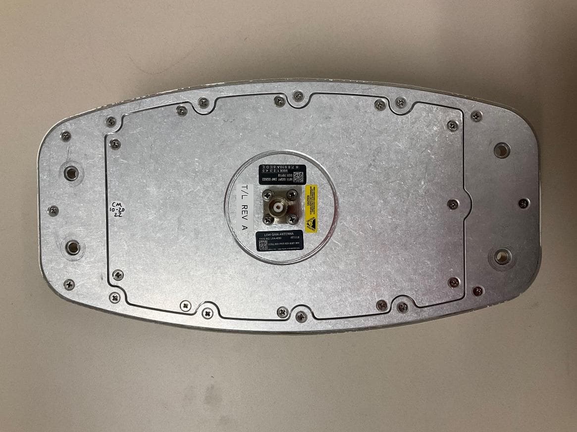
Jan 23, 2023IRT-4200 SATCOM System
Equipment Class
TNB - Licensed Non-Broadcast Station Transmitter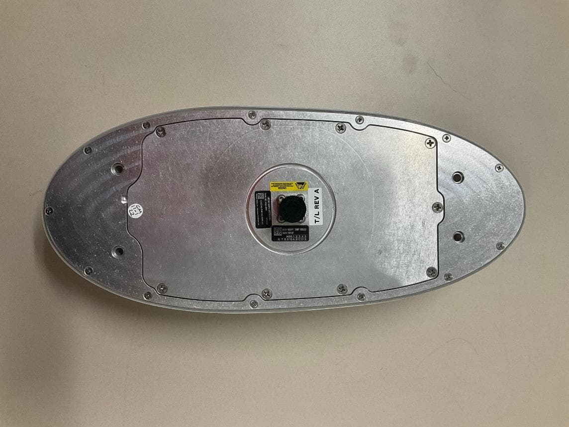
AJK8223586
Jan 23, 2023IRT-4400 SATCOM System
Equipment Class
TNB - Licensed Non-Broadcast Station Transmitter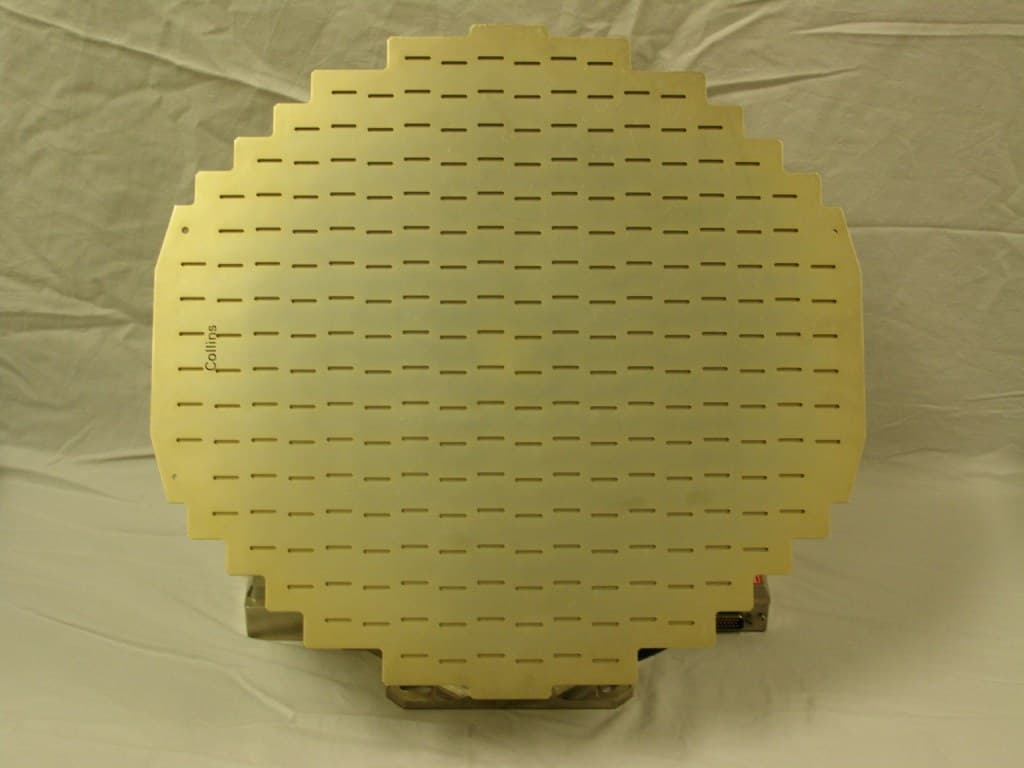
AJK8222259
Nov 11, 2015Weather Radar
Equipment Class
TNB - Licensed Non-Broadcast Station Transmitter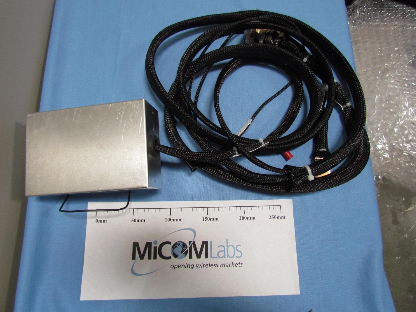
AJK8223132
May 20, 2015Information Management System
Equipment Class
DTS - Digital Transmission System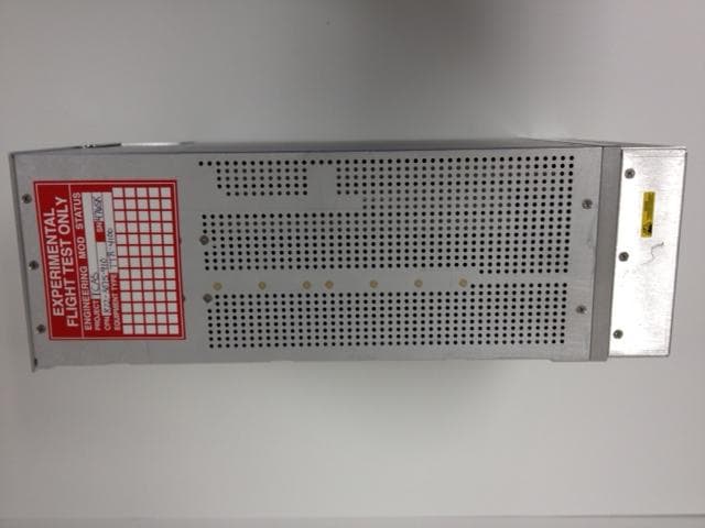
AJK8223075
Mar 04, 2013TCAS II Transmitter/Receiver
Equipment Class
TNB - Licensed Non-Broadcast Station Transmitter