AJK8221772Satellite High Speed Data Transceiver
Rockwell Collins Inc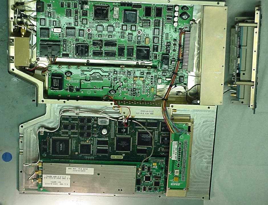
Click to zoom
Application Details
- Equipment Class
- TNB - Licensed Non-Broadcast Station Transmitter
- Date of Grant
- Apr 20, 2003
- Application Purpose
- Original Equipment
- Date of Application
- Oct 01, 2002
- Equipment Note
- Satellite High Speed Data Transceiver
- Frequency Range
- 1626.50000000 - 1660.50000000
- Company
- Rockwell Collins Inc
- Country
- United States
Documents & Files
Document Text
Text extracted from the exhibit documents filed with the FCC. Open a document above to read the original.
Users Manual
USER’S MANUALS MANUALS Rockwell Collins, Inc. does not supply an instruction book with the HST-900 SATCOM transceiver. The transceiver is supplied to airframe manufacturers and airlines, and designed to meet the requirements of Inmarsat. Operating instructions are not necessary because the unit is part of a larger satellite communications system. Rockwell Collins does produce the HST-900 Component Maintenance Manual, a comprehensive installation manual which, pursuant to an agreement with the FCC staff, is available upon request but in not included in this electronic exhibit.
Cover Letter(s)
September 18, 2002 Federal Aviation Administration Mr. George Sakai, ASR-1 Program Director Spectrum Engineering Division 800 Independence Avenue, SW Room 715 Washington, DC 20591 Re: FAA Notification of FCC Equipment Approval Under FCC Part 87 HST- 900 High Speed Data Transceiver Mr. Sakai: In accordance with the requirements of the Federal Communication Commission Rules and Regulations, Part 87.147(d), Rockwell Collins, Inc. hereby notifies the Federal Aviation Administration of its simultaneous filing with the FCC of an application for type acceptance on FCC Form 731 of equipment intended for transmission in frequency ranges set forth in FCC rules Part 87.147(d)(3) which require FAA notification. The application for type acceptance covers Rockwell Collins HST - 900 High Speed Data Transceiver. One complete set of the filing documents is enclosed, including a copy of Form 731, a detailed product description and test data for the HST - 900. Please direct any questions regarding this filing to Mr. Joe Cramer, (703) 516-8213. Respectfully Submitted, Maggie O’Neill Administrative Assistant Governmental & Regulatory Affairs cc: Federal Communications Commission
Cover Letter(s)
Washington Office 1300 Wilson Boulevard, Suite 200 Arlington, VA 22209-2307 October 3, 2002 Federal Communications Commission Office of Engineering and Technology Application Filed Via OET Laboratory Electronic Filing Site https://gullfoss.fcc.gov/prod/oet/index.html Re: Equipment Authorization Under Part 87 Certification HST-900 High-Speed Transceiver FCC ID: AJK8221772 Gentlemen: In accordance with the provisions of 47 CFR 0.459 and 0.457(d)(2)(I), Rockwell Collins, Inc. hereby request that Attachment 1 – Circuit Diagrams for the HST- 900 High Speed SATCOM Transceiver be withheld from public inspection. This application was electronically filed on October 2, 2002 and corresponds to FCC ID AJK8221772. Attachment 1 contains confidential commercial information or technical data customarily guarded from competitors and is, therefore, exempt from disclosure under Exemption 4 of the Freedom of Information Act [5 USC 522(b)(4)] because disclosure could reasonably be expected to cause substantial competitive harm. Your early consideration of the Application is respectfully requested. Please direct all inquiries to Mr. Joe Cramer of this office at (703) 516-8213. Respectfully submitted, Linda C. Sadler Director Federal Affairs
Cover Letter(s)
Washington Office December 18, 2002 Mr. Andrew Leimer Federal Communications Commission 445 12 th Street, SW Washington DC, 20554 Dear Mr. Leimer, This letter is in response to your correspondence dated November 7, 2002, Correspondence Reference Number 24302. Your correspondence asked three questions: 1. “The Test Report mentions that there is a waiver for the 16QAM modulation. Please upload this as an exhibit. 2. Upload the FAA coordination letter when received. 3. I am confused on the power. You asked for 0.159 Watts. Is this EIRP? Explain where this figure came from.” Below are the responses to your questions and comments: 1. On November 15, 2002, Rockwell Collins submitted the waiver request to the Wireless Bureau. We have not yet received a response to our waiver request. Rockwell Collins is working with the Wireless Bureau to obtain this waiver. As soon as the waiver is granted, we will submit it. 2. Rockwell Collins submitted the FAA coordination letter today, December 18, 2002. 3. Output power is discussed in Section 2.6 of our test report. Unfortunately, our engineers found one error in Section 2.6. The first sentence currently states: “(as measured at the antenna terminals)”. It should have read: “(as measured at the HST-900 output terminals)”. Therefore, 0.159 Watts or +22dBm is the maximum power output of the HST-900. The HST-900 only operates as an exciter. The signal leaving the HST-900 is then amplified by the High Power Amplifier which is currently certified by the FCC (AJK8220953) and then the signal is sent to the antenna. Thank you for your consideration of this matter. If you have any additional questions, please feel free to contact me at 703-516-8213. Sincerely, Joseph Cramer Manager Governmental and Regulatory Affairs
External Photos
Attachment 3 Equipment Photographs HST-900 FCC Type Certification Report Attachment 3 – Equipment Photographs CPN 815-4601-001 Rev: - Rockwell Collins, Inc. CAGEC 4V792 Page A3-2 External View - Front HST-900 FCC Type Certification Report Attachment 3 – Equipment Photographs CPN 815-4601-001 Rev: - Rockwell Collins, Inc. CAGEC 4V792 Page A3-3 External View - Rear HST-900 FCC Type Certification Report Attachment 3 – Equipment Photographs CPN 815-4601-001 Rev: - Rockwell Collins, Inc. CAGEC 4V792 Page A3-4 Internal View, All Assemblies HST-900 FCC Type Certification Report Attachment 3 – Equipment Photographs CPN 815-4601-001 Rev: - Rockwell Collins, Inc. CAGEC 4V792 Page A3-5 Channel Card – Top View HST-900 FCC Type Certification Report Attachment 3 – Equipment Photographs CPN 815-4601-001 Rev: - Rockwell Collins, Inc. CAGEC 4V792 Page A3-6 Channel Card – Bottom View HST-900 FCC Type Certification Report Attachment 3 – Equipment Photographs CPN 815-4601-001 Rev: - Rockwell Collins, Inc. CAGEC 4V792 Page A3-7 Channel Card RF Daughter board – Top View HST-900 FCC Type Certification Report Attachment 3 – Equipment Photographs CPN 815-4601-001 Rev: - Rockwell Collins, Inc. CAGEC 4V792 Page A3-8 Channel Card RF Daughter board – Bottom View HST-900 FCC Type Certification Report Attachment 3 – Equipment Photographs CPN 815-4601-001 Rev: - Rockwell Collins, Inc. CAGEC 4V792 Page A3-9 Data Processor – Top View HST-900 FCC Type Certification Report Attachment 3 – Equipment Photographs CPN 815-4601-001 Rev: - Rockwell Collins, Inc. CAGEC 4V792 Page A3-10 Data Processor – Bottom View
ID Label/Location Info
Attachment 2 Nameplate Label Drawings HST-900 FCC Type Certification Report Attachment 2 - Nameplate CPN 815-4601-001 Rev: - Rockwell Collins, Inc. CAGEC 4V792 Page A2-2 The following details the front panel nameplate proposed for the HST-900, and a diagram depicting the nameplate location on the unit. HST-900 FCC Type Certification Report Attachment 2 - Nameplate CPN 815-4601-001 Rev: - Rockwell Collins, Inc. CAGEC 4V792 Page A2-3 HST-900 Front Panel showing nameplate location
Internal Photos
Attachment 3 Equipment Photographs HST-900 FCC Type Certification Report Attachment 3 – Equipment Photographs CPN 815-4601-001 Rev: - Rockwell Collins, Inc. CAGEC 4V792 Page A3-2 External View - Front HST-900 FCC Type Certification Report Attachment 3 – Equipment Photographs CPN 815-4601-001 Rev: - Rockwell Collins, Inc. CAGEC 4V792 Page A3-3 External View - Rear HST-900 FCC Type Certification Report Attachment 3 – Equipment Photographs CPN 815-4601-001 Rev: - Rockwell Collins, Inc. CAGEC 4V792 Page A3-4 Internal View, All Assemblies HST-900 FCC Type Certification Report Attachment 3 – Equipment Photographs CPN 815-4601-001 Rev: - Rockwell Collins, Inc. CAGEC 4V792 Page A3-5 Channel Card – Top View HST-900 FCC Type Certification Report Attachment 3 – Equipment Photographs CPN 815-4601-001 Rev: - Rockwell Collins, Inc. CAGEC 4V792 Page A3-6 Channel Card – Bottom View HST-900 FCC Type Certification Report Attachment 3 – Equipment Photographs CPN 815-4601-001 Rev: - Rockwell Collins, Inc. CAGEC 4V792 Page A3-7 Channel Card RF Daughter board – Top View HST-900 FCC Type Certification Report Attachment 3 – Equipment Photographs CPN 815-4601-001 Rev: - Rockwell Collins, Inc. CAGEC 4V792 Page A3-8 Channel Card RF Daughter board – Bottom View HST-900 FCC Type Certification Report Attachment 3 – Equipment Photographs CPN 815-4601-001 Rev: - Rockwell Collins, Inc. CAGEC 4V792 Page A3-9 Data Processor – Top View HST-900 FCC Type Certification Report Attachment 3 – Equipment Photographs CPN 815-4601-001 Rev: - Rockwell Collins, Inc. CAGEC 4V792 Page A3-10 Data Processor – Bottom View
Operational Description
ATTACHMENT 6 - Product Description Overview The HST-900 is an additional unit designed to work with the existing SAT-906 SATCOM system. The original SATCOM system consists of the following previously FCC certified components: Type Number Name Manufacturer FCC ID SDU-906-1 (1 channel version) Satellite Data Unit Rockwell Collins AJKPN822-0309 SDU-906-2 (2 channel version) Satellite Data Unit Rockwell Collins AJKPN822-0310 SDU-906-3 (3 channel version) Satellite Data Unit Rockwell Collins AJKPN822-0311 SDU-906-4 (4 channel version) Satellite Data Unit Rockwell Collins AJKPN822-0312 SDU-906-5 (5 channel version) Satellite Data Unit Rockwell Collins AJKPN822-0313 SDU-906-6 (6 channel version) Satellite Data Unit Rockwell Collins AJKPN822-0314 RFU-900 Radio Frequency Unit Rockwell Collins AJKPN822-8849 HPA-901A High Power Amplifier Rockwell Collins AJKPN8220953 Antenna System various n/a Table 1 – List of Equipment The units listed above have all previously received FCC Type Certification. The SDU- 906 and HPA-901A require software modifications to support the addition of the HST- 900. The modifications do not result in changes that affect previously submitted test data for these units. The changes necessary to add an HST-900 to the existing SAT-906 System are highlighted in the shaded area of the figure below: Provision for High Speed Data Tx RF Rx RF Cockpit 1 SCDU 429 SDU-906-X RFU- 900 HPA- 901A Rx IF Tx IF Tx RF 429 429 429 429 CEPT E1 Bus Mic Headset Cockpit 2 Mic Headset (SCDU Controlled) CTU I/O ARINC 429Data HST-900 M4 - Euro ISDN IPDS - 10 Base T Analog Analog Rx RF Rx RF Tx RF IPDS - RS-232 Transmit Disable Discrete SATCOM Cntl IRS Input IF In IF Out RFU In HPA In HST Out (xtalk) HST Disable 429 RFU Out Multi Out BSU LNA/ D HGA BSU In Receive Xmit Ant. Subsystem HST In (xtalk) 429 429 429 Command/Control ARINC 429 X-Talk Figure 1 - SAT-906 System with HST-900 The HST-900 will add the INMARSAT Swift 64 service to the existing INMARSAT aeronautical services all ready supported by the SAT-906 system. By incorporating the Swift 64 service from INMARSAT, the HST-900 High-Speed Transceiver will provide 64 kilobits per second connectivity using the existing SAT-906 antenna and high- power amplifier, HPA-901A. The HST-900 supplies interfaces to Ethernet, ISDN and RS-232 which will provide real time passenger e-mail and Internet access as well as the provisioning for other future high speed data applications such as real time cabin surveillance to the ground, file server and integrated information systems cockpit applications. HST-900 Equipment Specifications CHARACTERISTIC SPECIFICATION Digital interface Crosstalk Bus High-speed ARINC 429 input and output Ethernet User Interface 10 Base T input and output ISDN User Interface 64 kbps ISDN Euro input and output RS-232 User MPDS Interface 115.2 kbps RS-232 input and output RS-232 Data Loader Port 115.2 kbps RS-232 input and output Input characteristics Frequency range 1530.0 to 1559.0 MHz Impedance 50 Ω nominal Vswr 2.0:1 max Signal input level -100 dBm to -60 dBm Output characteristics Frequency range 1626.5 to 1660.5 MHz Impedance 50 Ω nominal Load vswr 2.0:1 operational, infinite, survival Output power -6.5 dBm to 22 dBm in 0.5 dB increments Table 2 – Equipment Specifications HST-900 Hardware Overview The diagram shows the major functional blocks of the HST-900 unit. ARINC Connector 115VAC Channel Card Data Processor ARINC 429 Front Panel Connector Data (S/T, RS232) Power Supply 10 MHz Reference ARINC Connector Control (RS232) Control (RS232) Control (RS232) Front Panel LEDs RF Data (S/T, RS232, 10BaseT) Output Amplifier Data Loader Data Loader Figure 2 - HST-900 Functional Block Diagram Mechanical The HST-900 is housed in a 2-MCU-size unit with mounting requirements according to the ARINC600 specification. The HST-900 chassis is designed for either forced air or convection cooling. The front panel contains a data loader connector used to upload data to the HST-900 and set of LEDs to indicate unit status. It also contains a “self-test” button and corresponding LED indicators for active operator maintenance. A backplane assembly interfaces the Arinc 600 connector with the power supply, channel card, data processor card, and output amplifier. The HST-900 also contains an ovenized high stability crystal oscillator to provide a stable 10 MHz reference to the channel card. Channel Card The Channel Card contains the entire physical layer to L band and the protocols of an M4 terminal. In addition to the basic M4 (including MPDS) functionality, the Channel Card interfaces with the Data Processor for command and control functions. Interfaces between the Channel Card and the Data Processor fall into the broad categories of Operational, BITE, Maintenance and Test and Approval. Data interfaces to the Channel Card are ISDN BRI S/T for circuit switched data and RS-232 for packet data (MPDS). Voice services shall not be supported. Data Processor The purpose of the Data Processor is twofold: Control The Data Processor shall mediate between the Channel Card and the SDU, performing protocol conversion as required ensuring proper control of the HST-900. It shall also provide configuration and testing capabilities. User Data The Data Processor shall provide data conversion between the ISDN and RS232 on the Channel Card and other interfaces as required (i.e., 10BaseT Ethernet). This may include providing OSI Layer 2 and Layer 3 services. Power Supply The Power Supply provides regulated power to the Channel Card, External Reference, Output Amplifier and Data Processor. External Reference The External Reference provides a stable 10 MHz reference signal to the Channel Card. Output Amplifier The Output Amplifier increases the power of the RF signal from the Channel Card to the required level. Backplane The Backplane is a passive module that provides interconnection between all other modules of the HST-900 and to the outside world.
Parts List/Tune Up Info
ATTACHMENT 7 - PARTS LIST/TUNE-UP INFORMATION PARTS LIST The HST-900 contains the following modules: Chassis Assembly (Mechanical) Channel Card Data Processor Card Power Supply External Reference Oscillator Output Amplifier module Backplane (Passive Interconnect Card) A description of these modules can be found in Attachment 6 – Product Description. TUNE UP PROCEDURE The HST-900 transmitter does not require tune up during construction, maintenance or operation. The only adjustable component in the HST-900 is the High Stability Reference Oscillator, which is adjusted for proper frequency prior to unit assembly. No transmitter controls are available to the operator.
Test Report
© Copyright 2002 Rockwell Collins, Inc. All rights reserved Page 1 of 46 HST-900 FCC Type Certification Report 815-4601-001 Rev - Rockwell Collins, Inc. 400 Collins Rd NE Cedar Rapids, Iowa 52498 CAGEC 4V792 HST-900 FCC Type Certification Report CPN 815-4601-001 Rev: - Rockwell Collins, Inc. CAGEC 4V792 Page 2 of 46 Notices and Signatures Notices This document is a paper representation of the master copy which is maintained in the Product Development Manager (PDM) database. This document was prepared using the following: Microsoft Word 2002 Visio 5.0 for Microsoft Windows Approval Signatures Name Signature Approved By: R. L. Breitwisch Approved By SCL Approved By SQE HST-900 FCC Type Certification Report CPN 815-4601-001 Rev: - Rockwell Collins, Inc. CAGEC 4V792 Page 3 of 46 Revision History Ver/Rev Doc Chg # Release Date Originator Reasons for Change 001/- R. L. Breitwisch HST-900 FCC Type Certification Report CPN 815-4601-001 Rev: - Rockwell Collins, Inc. CAGEC 4V792 Page 4 of 46 Forward The following information is being submitted in compliance with Part 2 and Part 87 of Title 47, Code of Federal Regulations – Telecommunications, for certification of the Rockwell Collins High Speed Data Transceiver. Type Number: HST-900 Collins Part Number: 822-1772-xxx FCC ID: AJK8221772 The units tested for the purposes of this report were engineering units representative of production configurations. HST-900 FCC Type Certification Report CPN 815-4601-001 Rev: - Rockwell Collins, Inc. CAGEC 4V792 Page 5 of 46 Table of Contents Notices and Signatures............................................................................................................2 Notices.............................................................................................................................2 Approval Signatures........................................................................................................2 Revision History.........................................................................................................................3 Forward.........................................................................................................................................4 1 Product Description...............................................................................................................7 1.1 Overview....................................................................................................................7 1.2 HST-900 Equipment Specifications..........................................................................8 1.3 HST-900 Hardware Overview...................................................................................9 1.4 Mechanical.................................................................................................................9 1.5 Channel Card.............................................................................................................9 1.6 Data Processor..........................................................................................................9 1.6.1 Control.................................................................................................................9 1.6.2 User Data..........................................................................................................10 1.7 Power Supply...........................................................................................................10 1.8 External Reference..................................................................................................10 1.9 Output Amplifier.......................................................................................................10 1.10 Backplane..............................................................................................................10 2 Technical Report..................................................................................................................11 2.1 Name and Address [2.1033(c)(1)]...........................................................................11 2.2 FCC Identifier [2.1033(c)(2)]....................................................................................11 2.3 Installation and Operation Manuals [2.1033(c)(3)]..................................................11 2.4 Type or Types of Emission [2.1033(c)(4)]...............................................................11 2.5 Frequency Range [2.1033(c)(5)].............................................................................11 2.6 Range of Operating Power Values [2.1033(c)(6)]...................................................11 2.7 Maximum Power Rating [2.1033(c)(7)]...................................................................12 2.8 DC Voltages and Currents [2.1033(c)(8)]...............................................................12 2.9 Tune Up Procedure [2.1033(c)(9)]..........................................................................12 2.10 Schematics and Circuit Diagrams [2.1033(c)(10)]................................................12 2.11 Nameplate Label Drawings [2.1033(c)(11)]..........................................................13 2.12 Equipment Photographs – External [2.1033(c)(12)].............................................13 2.13 Digital Modulation System [2.1033(c)(13)]............................................................13 2.14 Required Measurements [2.1033(c)(14)]..............................................................13 3.0 Test Procedures and Results........................................................................................14 3.1 Test Procedure and Compliance Matrix..............................................................14 3.2 Test Requirements Matrix....................................................................................14 3.3 Test Equipment....................................................................................................14 3.4 RF Power Output................…
Text truncated - open the document above for the full version.
Test Report
Attachment 5 EMC Plots HST-900 FCC Type Certification Report Attachment 5 – EMC Plots CPN 815-4601-001 Rev: - Rockwell Collins, Inc. CAGEC 4V792 Page A5-2 HST-900 FCC Type Certification Report Attachment 5 – EMC Plots CPN 815-4601-001 Rev: - Rockwell Collins, Inc. CAGEC 4V792 Page A5-3 HST-900 FCC Type Certification Report Attachment 5 – EMC Plots CPN 815-4601-001 Rev: - Rockwell Collins, Inc. CAGEC 4V792 Page A5-4 HST-900 FCC Type Certification Report Attachment 5 – EMC Plots CPN 815-4601-001 Rev: - Rockwell Collins, Inc. CAGEC 4V792 Page A5-5 HST-900 FCC Type Certification Report Attachment 5 – EMC Plots CPN 815-4601-001 Rev: - Rockwell Collins, Inc. CAGEC 4V792 Page A5-6 HST-900 FCC Type Certification Report Attachment 5 – EMC Plots CPN 815-4601-001 Rev: - Rockwell Collins, Inc. CAGEC 4V792 Page A5-7 HST-900 FCC Type Certification Report Attachment 5 – EMC Plots CPN 815-4601-001 Rev: - Rockwell Collins, Inc. CAGEC 4V792 Page A5-8 HST-900 FCC Type Certification Report Attachment 5 – EMC Plots CPN 815-4601-001 Rev: - Rockwell Collins, Inc. CAGEC 4V792 Page A5-9 HST-900 FCC Type Certification Report Attachment 5 – EMC Plots CPN 815-4601-001 Rev: - Rockwell Collins, Inc. CAGEC 4V792 Page A5-10 HST-900 FCC Type Certification Report Attachment 5 – EMC Plots CPN 815-4601-001 Rev: - Rockwell Collins, Inc. CAGEC 4V792 Page A5-11 Note: The limit line displayed above as “FCC 87.139 (i) (1) is incorrect. See the procedure text for the correct pass/fail threshold. HST-900 FCC Type Certification Report Attachment 5 – EMC Plots CPN 815-4601-001 Rev: - Rockwell Collins, Inc. CAGEC 4V792 Page A5-12 Note: The limit line displayed above as “FCC 87.139 (i) (1) is incorrect. See the procedure text for the correct pass/fail threshold.
Test Report
Washington Office October 23, 2002 Federal Communications Commission Office of Engineering and Technology Application Filed Via OET Laboratory Electronic Filing Site https://gullfoss.fcc.gov/prod/oet/index.html Re: Equipment Authorization Under Part 87 Certification HST-900 High-Speed Transceiver FCC ID: AJK8221772 In accordance with the requirements of the Federal Communication Commission Rules and Regulations, Rockwell Collins, Inc. hereby notifies the Federal Communications Commission of additional testing information for its certification application for the Rockwell Collins HST - 900 High Speed Data Transceiver. Figure 8 of Section 3.6 “Occupied Bandwidth”, measured the bandwidth which contained 99.5% of the transmitted energy. However, 47CFR 87.135(a), defines the Occupied Bandwidth as “the width of a frequency band such that, below the lower and above the upper frequency limits, the mean powers emitted are each equal to 0.5 percent of the total mean power of a given emission.” For a symmetrical spectrum, the proper test equipment settings should have been established as 99.0% of the transmitted energy. This error resulted in an occupied bandwidth measurement greater than if measured properly. Rockwell Collins requests that the attached spectrum plot replace the spectrum plot contained as Figure 8 in Section 3.6.2 of our original submission. In addition, we request that the text of Section 3.6.3 be replaced with the following text to accurately reflect the new measured data. 3.6.3 Test Results Discussion: The 3000 bps signaling channel has an occupied bandwidth measured at 16.00 kHz. This is within the 25 kHz Authorized Bandwidth specified in 87.137 for aircraft earth stations using G1D emissions. The 134400 bps 16-QAM user data channel has an occupied bandwidth measured at 39.84 kHz. This higher data rate class of emission (D1D, D1E, D1W) and associated occupied bandwidth is not accommodated by the table of 87.137. Rockwell Collins intends to submit a Request for Waiver to accommodate the new emission type utilized by the INMARSAT Swift64 service and their associated occupied bandwidths. Please direct any questions regarding this filing to Mr. Joe Cramer, (703) 516-8213. Respectfully Submitted, Maggie O’Neill Administrative Assistant Governmental & Regulatory Affairs cc: Federal Communications Commission
Contact Information
Applicant
Thomas A. Voltero(Senior Counsel)
Technical Contact
Rockwell Collins, Inc.Joseph Cramer
[email protected]703-516-8213
1300 Wilson Blvd. · Arlington, Virginia · United States
Technical Specifications
| # | Rule Parts | Frequency Range | Power Output | Emission | Tolerance |
|---|---|---|---|---|---|
| 2 | 87 | 1.63 GHz - 1.66 GHz | 159.00 mW | 40K0D7W | 320 Hz |
Other Applications from Rockwell Collins Inc
AJK8223587
Jan 23, 2023IRT-4200 SATCOM System
Equipment Class
TNB - Licensed Non-Broadcast Station Transmitter
AJK8223586
Jan 23, 2023IRT-4400 SATCOM System
Equipment Class
TNB - Licensed Non-Broadcast Station Transmitter
AJK8222259
Nov 11, 2015Weather Radar
Equipment Class
TNB - Licensed Non-Broadcast Station Transmitter
AJK8223132
May 20, 2015Information Management System
Equipment Class
DTS - Digital Transmission System
AJK8223075
Mar 04, 2013TCAS II Transmitter/Receiver
Equipment Class
TNB - Licensed Non-Broadcast Station Transmitter