AJK8222127WRAU-2120
Rockwell Collins Inc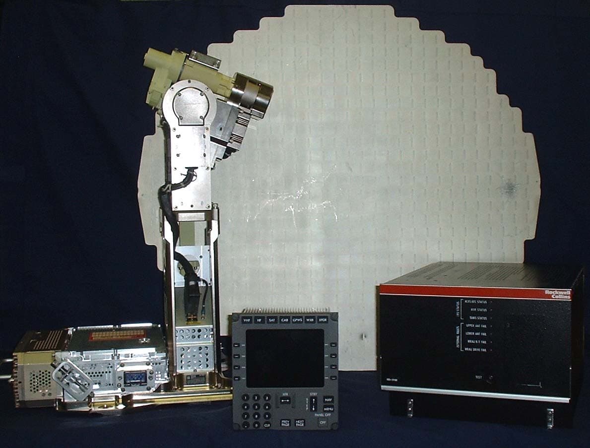
Click to zoom
Application Details
- Equipment Class
- TNB - Licensed Non-Broadcast Station Transmitter
- Date of Grant
- Sep 09, 2007
- Application Purpose
- Original Equipment
- Date of Application
- Jun 12, 2007
- Equipment Note
- WRAU-2120
- Frequency Range
- 9320.41279800 - 9400.41279600
- Company
- Rockwell Collins Inc
- Country
- United States
Documents & Files
Document Text
Text extracted from the exhibit documents filed with the FCC. Open a document above to read the original.
Users Manual
CPN 963-7691-001 Rev - Rockwell Collins - Proprietary Information Page H-1 WRAU-2120 Exhibit H – User’s Manual WRAU-2120 CPN 963-7691-001 Rev - Rockwell Collins - Proprietary Information Page H-2 Exhibit H – User’s Manual Rockwell Collins does not supply operating instructions with the WRAU-2120, which is designed to meet the requirements of ARINC 600, 601, and 708A, and RTCA documents DO-220, DO-160E, and DO-178B and is operated by trained pilots. Rockwell Collins does produce a comprehensive installation manual which, pursuant to an agreement with the FCC staff, is available upon request but is not included in this electronic exhibit.
Attestation Statements
WRAU-2120 ExhibitB-AttestationStatement CERTIFICATE TheWRAU-2120hasbeentestedinaccordancewiththerequirementscontainedintheappropriate Commissionregulations.Tothebestofmyknowledge,thesetestswereperformedusingmeasurement proceduresconsistentwithindustryorCommissionstandardsanddemonstratethattheWRAU-2120 complieswiththeappropriatestandards.Eachunitmanufactured,imported,ormarketed,asdefinedinthe Commission'sregulations,willconformtothesample(s)testedwithinthevariationsthatcanbeexpected duetoquantityproductionandtestingona statisticalbasis.I herebycertifythatthetestsdescribedinthis reportwereperformedatmydirectionandundermysupervision,andthattheresultsandtestdata containedinthisreporttrulyandaccuratelyshowtheperformanceofthetransmitterintheWRAU-2120 transceiver.I furthercertifythattheancillaryinformationcontainedhereinaccuratelyreflectsthedesign, installationrequifements,alignmentprocedures,andoperationalinstructionsofandforthistransceiver. Signed. (SignatureonOriginal FileintheCedarRapidsCertificationOffice) CPN963-7691-001Rev- RockwellCollins- ProprietaryInformation PageB-2 ---
External Photos
CPN 963-7691-001 Rev - Rockwell Collins - Proprietary Information Page C-1 WRAU-2120 Exhibit C - Equipment Photographs: External Views WRAU-2120 CPN 963-7691-001 Rev - Rockwell Collins - Proprietary Information Page C-2 Exhibit C – Equipment Photographs: External Views List of Figures Figure C-1. Weather Radar System Components.......................................................................... 3 Figure C-2. WRAU-2120 ................................................................................................................ 4 Figure C-3. WRAU-2120 (opp. side) ..............................................................................................5 Figure C-4. Flatplate Antenna ........................................................................................................ 6 Figure C-5. RTM-2100 Receiver/Transmitter Module .................................................................... 7 Figure C-6. RTM-2100 Receiver/Transmitter Module (opp. side) .................................................. 8 Figure C-7. RTM-2100 Receiver/Transmitter Module with RF section detached .......................... 9 WRAU-2120 CPN 963-7691-001 Rev - Rockwell Collins - Proprietary Information Page C-3 Figure C-1. Weather Radar System Components Tuning and Control Panel (TCP) RTM-2100 Receiver/Transmitter DRV-2120 Antenna Pedestal WFA-701X Antenna Flatplate ISS-2100 Contains WXR Processor Card WRAU-2120 CPN 963-7691-001 Rev - Rockwell Collins - Proprietary Information Page C-4 Figure C-2. WRAU-2120 RTM ID Labels WRAU-2120 CPN 963-7691-001 Rev - Rockwell Collins - Proprietary Information Page C-5 Figure C-3. WRAU-2120 (opp. side) DRV ID Label WRAU-2120 CPN 963-7691-001 Rev - Rockwell Collins - Proprietary Information Page C-6 Figure C-4. Flatplate Antenna WRAU-2120 CPN 963-7691-001 Rev - Rockwell Collins - Proprietary Information Page C-7 Figure C-5. RTM-2100 Receiver/Transmitter Module RTM-2100 ID Label WRAU-2120 CPN 963-7691-001 Rev - Rockwell Collins - Proprietary Information Page C-8 Figure C-6. RTM-2100 Receiver/Transmitter Module (opp. side) WRAU-2120 CPN 963-7691-001 Rev - Rockwell Collins - Proprietary Information Page C-9 Figure C-7. RTM-2100 Receiver/Transmitter Module with RF section detached RTM-2100 ID Label
ID Label/Location Info
CPN 963-7691-001 Rev - Rockwell Collins- Proprietary Information Page A-1 WRAU-2120 Exhibit A – ID Label and Location Information WRAU-2120 CPN 963-7691-001 Rev - Rockwell Collins - Proprietary Information Page A-2 Exhibit A – ID Label and Location Information List of Figures Figure A-1. RTM-2100 ID Label for TSO C63c Compliance .......................................................... 3 Figure A-2. RTM-2100 ID Label for TSO C63d Compliance .......................................................... 3 Figure A-3. WRAU-2120 showing RTM-2100 ID Label locations .................................................. 4 Figure A-4. RTM-2100 with ID Label .............................................................................................. 5 WRAU-2120 CPN 963-7691-001 Rev - Rockwell Collins - Proprietary Information Page A-3 Exhibit A – ID Label and Location Information The RTM-2100 ID label is shown below in Figure A-1 and Figure A-2. This label includes the FCC ID along with the Collins Part Number and other applicable information. Figure A-1 shows the ID label used for units meeting FAA TSO C63c requirements. Figure A-2 shows the ID label used for units meeting FAA TSO C63d requirements. Both labels are shown here to allow for growth to C63d compliance once TSO C63d is released and the system shows compliance with the new requirements contained therein. Figure A-3 and Figure A-4 show the location of this label on the fully assembled WRAU-2120 and RTM-2100 unit, respectively. Figure A-1. RTM-2100 ID Label for TSO C63c Compliance Figure A-2. RTM-2100 ID Label for TSO C63d Compliance WRAU-2120 CPN 963-7691-001 Rev - Rockwell Collins - Proprietary Information Page A-4 Figure A-3. WRAU-2120 showing RTM-2100 ID Label locations RTM ID Labels WRAU-2120 CPN 963-7691-001 Rev - Rockwell Collins - Proprietary Information Page A-5 Figure A-4. RTM-2100 with ID Label RTM ID Label
Internal Photos
CPN 815-8719-001 Rev - Rockwell Collins - Proprietary Information Page I-1 WRAU-2120 Exhibit I – Equipment Photographs: Internal Views WRAU-2120 CPN 815-8719-001 Rev - Rockwell Collins - Proprietary Information Page I-2 Exhibit I – Internal Photos List of Figures Figure I-1. RTM-2120 with covers removed ................................................................................... 3 Figure I-2. RTM-2120 with power supply card exposed................................................................. 4 Figure I-3. RTM-2120 with DDS source removed .......................................................................... 5 Figure I-4. Direct Digital Synthesizer (DDS) Source card (top)...................................................... 6 Figure I-5. DDS Source card (bottom)............................................................................................ 6 Figure I-6. Digital Receiver (Sampler) card (top)............................................................................ 7 Figure I-7. Digital Receiver (Sampler) card (bottom)...................................................................... 7 Figure I-8. Antenna Drive card (top) ............................................................................................... 8 Figure I-9. Antenna Drive card (bottom) ......................................................................................... 8 Figure I-10. Power Supply card (top) ............................................................................................. 9 Figure I-11. Power Supply card (bottom) .......................................................................................9 Figure I-12. WXR processor card (top) ........................................................................................ 10 Figure I-13. WXR processor card (bottom) .................................................................................. 10 WRAU-2120 CPN 815-8719-001 Rev - Rockwell Collins - Proprietary Information Page I-3 Figure I-1. RTM-2120 with covers removed WRAU-2120 CPN 815-8719-001 Rev - Rockwell Collins - Proprietary Information Page I-4 Figure I-2. RTM-2120 with power supply card exposed WRAU-2120 CPN 815-8719-001 Rev - Rockwell Collins - Proprietary Information Page I-5 Figure I-3. RTM-2120 with DDS source removed WRAU-2120 CPN 815-8719-001 Rev - Rockwell Collins - Proprietary Information Page I-6 Figure I-4. Direct Digital Synthesizer (DDS) Source card (top) Figure I-5. DDS Source card (bottom) WRAU-2120 CPN 815-8719-001 Rev - Rockwell Collins - Proprietary Information Page I-7 Figure I-6. Digital Receiver (Sampler) card (top) Figure I-7. Digital Receiver (Sampler) card (bottom) WRAU-2120 CPN 815-8719-001 Rev - Rockwell Collins - Proprietary Information Page I-8 Figure I-8. Antenna Drive card (top) Figure I-9. Antenna Drive card (bottom) WRAU-2120 CPN 815-8719-001 Rev - Rockwell Collins - Proprietary Information Page I-9 Figure I-10. Power Supply card (top) Figure I-11. Power Supply card (bottom) WRAU-2120 CPN 815-8719-001 Rev - Rockwell Collins - Proprietary Information Page I-10 Figure I-12. WXR processor card (top) Figure I-13. WXR processor card (bottom)
RF Exposure Info
CPN 963-7691-001 Rev - Rockwell Collins - Proprietary Information Page K-1 WRAU-2120 Exhibit K - Radiation Exposure Information WRAU-2120 CPN 963-7691-001 Rev - Rockwell Collins - Proprietary Information Page K-2 Exhibit K - Radiation Exposure Information This section affirms compliance with respect to controlled and uncontrolled exposure limits for MPE/SAR. Requirements: The rules concerning RF radiation exposure are 1.1310, 2.1091 and 2.1093. FCC Section 1.1310 Table 1 defines the Maximum Permissible Exposure (MPE) power density limits for the frequency range from 1500 to 100,000 MHz as follows: (A) Controlled Exposures 5 mW/cm 2 (B) Uncontrolled Exposure 1 mW/cm 2 The WRAU-2120 Radar system antenna is mounted in the nose of air transport aircraft. This location is highly restricted to only airport maintenance personnel and is off limits to any general population. In addition, airline maintenance and ramp operating procedures do not allow the radar system to be powered up in the airport gate area where maintenance personnel have access to the aircraft. In addition, the nose of the aircraft is generally 8 to 10 feet above the ground and thus is inaccessible to any personnel without ladders or special lift equipment. These limited access restrictions place the WRAU-2120 under the definition of (A) Controlled Exposures which requires a MPE power density limit of 5 mW/cm 2 averaged over a 6 minute period. Section 2.1091(b) defines a “mobile device” as “a transmitting device designed to be used in other than fixed locations and to generally be used in such a way that a separation distance of at least 20 centimeters is normally maintained between the transmitters radiating structures and the body of the user(s) or nearby persons.” Since the WRAU-2120 antenna mounting location is behind the aircraft radome and inaccessible in normal usage to any personnel and is located greater than 20 centimeters from any persons, it falls under the definition of mobile device in the Section 2.1091 (b). The WRAU-2120 does not fall into any of the categories described in Section2.1091(c) that are subject to routine environmental evaluation for RF exposure. As such, the WRAU-2120 is “... categorically excluded from routine environmental evaluation for RF exposure prior to equipment authorization or use”. Radiation Hazard Assessment: The WRAU-2120 transmitter output is very low power. Under maximum operating conditions, the average power output of the radar is in the order of 1 watt, roughly equivalent to a small night light. For the purposes of evaluating the Radiation Hazard for the WRAU-2120 a report will be used that evaluated RF radiation hazard for the WXR-700X. The WRAU-2120 transmitter is equivalent to the WXR-700X transmitter. WRAU-2120 CPN 963-7691-001 Rev - Rockwell Collins - Proprietary Information Page K-3 Radiation Hazard Test Report: A Radiation Hazard study was performed on the WXR-700X in 1996 for the Department of the Air Force - Armstrong Laboratory (AFMC). Ref. “Consultative Letter, AL/OE-CL-1996-0159, Report of a Radio Frequency (RF) Radiation Hazard Survey of Pacer Crag C/KC-135 E/R Weather Radar System, WXR-700X”. The report is dated 10 May 1996. The purpose of the study was to “establish the electromagnetic field strengths associated with the use, operation and testing of the new WXR-700X radar, and to establish safe operating distanced for Air Force employees working near the new radar.” The report contains both a theoretical assessment of the permissible exposure limits and actual measurements of the RF radiated power density from the system operating at maximum duty cycle. The actual power density measurements were taken with the antenna scanning physically disabled to facilitate measurements. The antenna was fixed in a direction at zero degrees tilt pointing forward from the aircraft bulkhead. (In normal operation, the antenna would be scanning any time the transmitter were operating.) Power density measurements were taken along the radar beam axis at distances from 0 to 150 feet with the radar operating at maximum duty cycle. The highest power density reading was 0.13 mW/cm 2 at a distance of less than 1 foot from the antenna radiating surface. All other measurements were less. A comment in the report states “The levels measured from the WXR- 700X radar were barely distinguishable from the background noise in the area.” Report Conclusions for Normal Operating Conditions : “Based on analysis of the equipment parameters, theoretical hazard evaluations, and the field power density measurements, the WXR-700X radar, equipped with a flat plate, slot array antenna, does not produce power density levels that could reasonably be expected to exceed the PEL (Permissible Exposure Limit) under normal operating conditions. Therefore, it is not necessary to establish restricted access zones in front of the antenna under these conditions.” Compliance Statement: The WRAU-2120 does not exceed the Minimum Permissible Exposure (MPE) limits of 5 mW/cm 2 contained in FCC Section 1.1310 Table 1. The Radiation Hazard Test Report referenced above may be obtained by permission of the US Department of the Air Force.
Test Setup Photos
CPN 963-7691-001 Rev - Rockwell Collins - Proprietary Information Page G-1 WRAU-2120 Exhibit G – Test Setup Photographs WRAU-2120 CPN 963-7691-001 Rev - Rockwell Collins - Proprietary Information Page G-2 Exhibit G – Test Setup Photographs List of Figures Figure G-1. Bench Test Setup – Occupied Bandwidth, Antenna Spurious, Power Line Stability .. 3 Figure G-2. Frequency Stability vs. Temperature .......................................................................... 4 Figure G-3. Radiated Emission 150 kHz – 25 MHz........................................................................ 5 Figure G-4. Radiated Emission 25 MHz – 200 MHz ...................................................................... 6 Figure G-5. Radiated Emission 200 MHz – 1 GHz......................................................................... 7 Figure G-6. Radiated Emission 1 GHz – 18 GHz........................................................................... 8 Figure G-7. Radiated Emission 18 GHz – 26 GHz......................................................................... 9 Figure G-8. Radiated Emission 26 GHz – 40 GHz....................................................................... 10 WRAU-2120 CPN 963-7691-001 Rev - Rockwell Collins - Proprietary Information Page G-3 Figure G-1. Bench Test Setup – Occupied Bandwidth, Antenna Spurious, Power Line Stability WRAU-2120 CPN 963-7691-001 Rev - Rockwell Collins - Proprietary Information Page G-4 Figure G-2. Frequency Stability vs. Temperature WRAU-2120 CPN 963-7691-001 Rev - Rockwell Collins - Proprietary Information Page G-5 Figure G-3. Radiated Emission 150 kHz – 25 MHz WRAU-2120 CPN 963-7691-001 Rev - Rockwell Collins - Proprietary Information Page G-6 Figure G-4. Radiated Emission 25 MHz – 200 MHz WRAU-2120 CPN 963-7691-001 Rev - Rockwell Collins - Proprietary Information Page G-7 Figure G-5. Radiated Emission 200 MHz – 1 GHz WRAU-2120 CPN 963-7691-001 Rev - Rockwell Collins - Proprietary Information Page G-8 Figure G-6. Radiated Emission 1 GHz – 18 GHz WRAU-2120 CPN 963-7691-001 Rev - Rockwell Collins - Proprietary Information Page G-9 Figure G-7. Radiated Emission 18 GHz – 26 GHz WRAU-2120 CPN 963-7691-001 Rev - Rockwell Collins - Proprietary Information Page G-10 Figure G-8. Radiated Emission 26 GHz – 40 GHz
Contact Information
Applicant
Thomas A. Voltero(Director & Senior Counsel)
Non-Technical Contact
Rockwell Collins, Inc.John Gifft
[email protected]703.516.8213
Technical Specifications
| # | Rule Parts | Frequency Range | Power Output | Emission | Tolerance |
|---|---|---|---|---|---|
| 3 | 87 | 9.32 GHz - 9.40 GHz | 125 W | 120KP0N | 0.0107 % |
Other Applications from Rockwell Collins Inc
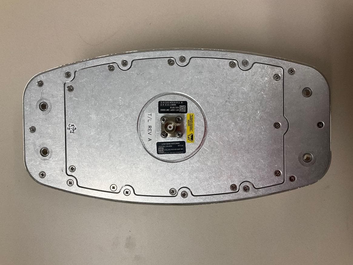
AJK8223587
Jan 23, 2023IRT-4200 SATCOM System
Equipment Class
TNB - Licensed Non-Broadcast Station Transmitter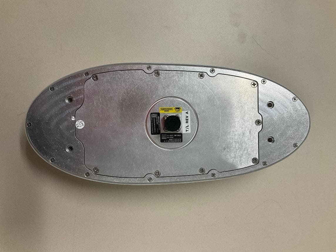
AJK8223586
Jan 23, 2023IRT-4400 SATCOM System
Equipment Class
TNB - Licensed Non-Broadcast Station Transmitter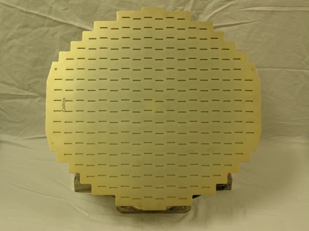
AJK8222259
Nov 11, 2015Weather Radar
Equipment Class
TNB - Licensed Non-Broadcast Station Transmitter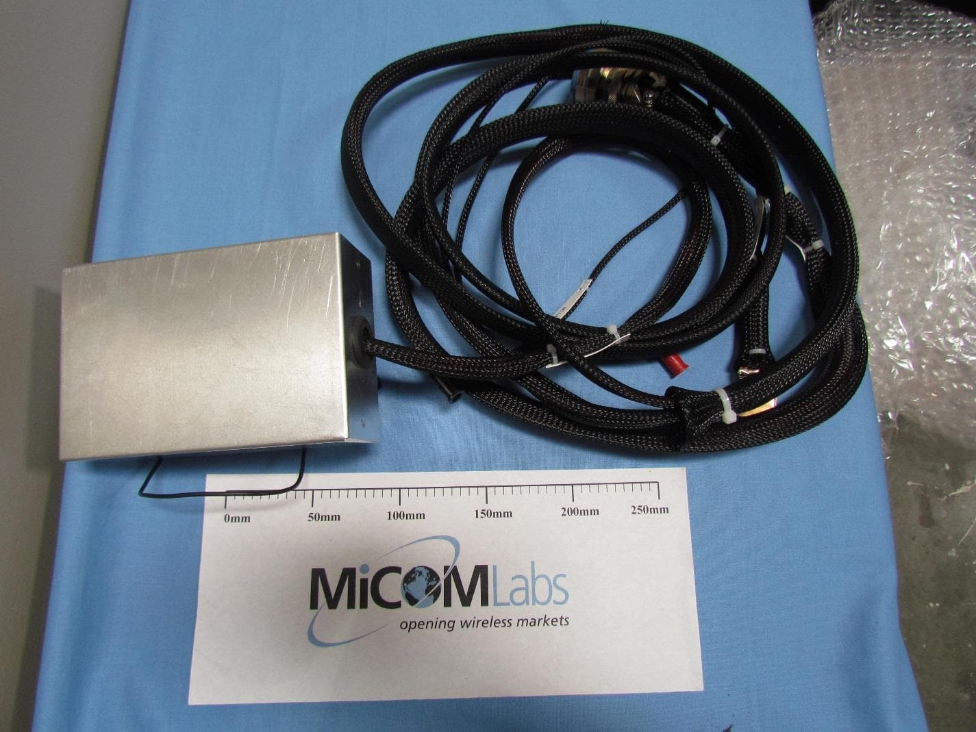
AJK8223132
May 20, 2015Information Management System
Equipment Class
DTS - Digital Transmission System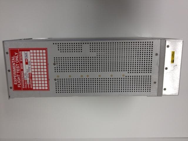
AJK8223075
Mar 04, 2013TCAS II Transmitter/Receiver
Equipment Class
TNB - Licensed Non-Broadcast Station Transmitter