AJK8222231HST-2110 High Speed Satellite Transceiver
Rockwell Collins Inc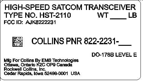
Click to zoom
Application Details
- Equipment Class
- TNB - Licensed Non-Broadcast Station Transmitter
- Date of Grant
- Oct 16, 2006
- Application Purpose
- Original Equipment
- Date of Application
- Aug 06, 2006
- Equipment Note
- HST-2110 High Speed Satellite Transceiver
- Frequency Range
- 1626.50000000 - 1660.50000000
- Company
- Rockwell Collins Inc
- Country
- United States
Documents & Files
Document Text
Text extracted from the exhibit documents filed with the FCC. Open a document above to read the original.
Users Manual
Exhibit H USER’S MANUAL 1.1. Installation and Operation Manuals [2.1033(c)(3)] Rockwell Collins does not supply operating instructions with the HST, which is designed to meet the requirements of ARINC 741 and RTCA DO-210D and is operated by trained pilots as part of the SATCOM system. Rockwell Collins does produce a comprehensive Installation Manual which, pursuant to agreement with FCC staff, is available upon request but is not included in this electronic exhibit.
Block Diagram
Exhibit E Product Description 1. Product Description 1.1. Overview The High Speed data Transceiver (HST), type numbers HST-2110 and HST-2120 are additional units designed to work with the existing SRT-2100 Satellite Data Unit (SDU). A complete SATCOM system consists of the following components: Type Number Name Manufacturer FCC ID SRT-2100 (3 channel version) Satellite Data Unit Rockwell Collins AJK8222023 High Gain Antenna System n/a various n/a Table 1 – List of Equipment The units listed above have previously received FCC Type Certification as necessary. The SRT-2100 requires software modifications to support the addition of the HST-2110 or HST-2120. The modifications do not result in changes that affect previously submitted test data for this unit. The changes necessary to add an HST-2110 or HST-2120 to the existing SRT-2100 System are highlighted in the outlined area of the figure below: Figure 1 - SRT-2100 System with HST The HST-2110 or HST-2120 will add the INMARSAT Swift 64 service to the existing INMARSAT aeronautical services already supported by the SRT-2100 system. By incorporating the Swift 64 service from INMARSAT, the HST High-Speed Transceiver will provide 64 kilobits per second connectivity using the existing SAT-2100 antenna and high- power amplifier. The HST supplies interfaces to Ethernet, ISDN and RS-232 which will provide real time passenger e-mail and Internet access as well as the provisioning for other future high speed data applications such as real time cabin surveillance to the ground, file server, Swift Broadband and integrated information systems cockpit applications. 1.2. HST-2110 and HST-2120 Equipment Specifications CHARACTERISTIC SPECIFICATION Digital interface Crosstalk Bus High-speed ARINC 429 input and output Ethernet User Interface 10 Base T input and output ISDN User Interface 64 kbps ISDN Euro input and output RS-232 User MPDS Interface 115.2 kbps RS -232 input and output RS-232 Data Loader Port 115.2 kbps RS -232 input and output Input characteristics Frequency range 1530.0 to 1559.0 MHz Impedance 50 Ω nominal VSWR 2.0:1 max Signal input level -100 dBm to -60 dBm Output characteristics Frequency range 1626.5 to 1660.5 MHz Impedance 50 Ω nominal Load VSWR 2.0:1 operational, infinite, survival Output power -6.5 dBm to 22 dBm in 0.5 dB increments Table 2 – Equipment Specifications 1.3. HST Hardware Overview The HST product line consists of the following LRUs: • The HST-2110, Collins Part Number 822-2231-020. This unit is designed to operate primary power of 115 VAC, 400Hz. It is similar to the previously Type Certified HST-900 except that it contains a new channel card (with a single RF module) replacing the current channel card. The new channel card refreshes technology and allows for future growth for future Inmarsat services such as SwiftBroadband. • The HST-2110, Collins Part Number 822-2231-010. This unit is designed to operate with 28V DC primary power. It is similar to the previously Type Certified HST-900 except that it contains a new channel card (with a single RF module) replacing the current channel card, and the 28V DC power supply. The new channel card refreshes technology and allows for future growth for future Inmarsat services such as SwiftBroadband. • The HST-2120, Collins Part Number 822-2233-010. This unit is designed to operate primary power of 115 VAC, 400Hz. It is similar to the previously Type Certified HST-900 except that it contains a new channel card, with two RF modules, replacing the current channel card. This unit supports two simultaneous channels of Swift64. The new channel card refreshes technology and allows for future growth for future Inmarsat services such as SwiftBroadband. Figure 2 shows the major functional blocks of the HST-2110 (single channel), Figure 3 shows the major functional blocks of the HST-2120 (dual channel). Figure 2 HST-2110 Block Diagram Figure 3 HST-2120 Block Diagram 1.4. Mechanical Both the HST-2110 and HST-2120 are housed in a 2-MCU-size unit with mounting requirements according to the ARINC 600 specification. The HST chassis is designed for either forced air or convection cooling. The front panel contains a data loader connector used to upload data to the HST and a set of LEDs to indicate unit status. It also contains a “self-test” button and corresponding LED indicators for active operator maintenance. A backplane assembly interfaces the ARINC 600 connector with the power supply, channel card, data processor card, and output amplifier. The HST also contains an ovenized high stability crystal oscillator to provide a stable 10 MHz reference to the channel card. 1.5. Channel Card The Channel Card contains the entire physical layer to L band and the protocols of an Inmarsat Swift64 terminal. In addition to the Inmarsat MISDN and MPDS protocol functionality, the Channel Card interfaces with the Data Processor for command and control functions. The Interfaces between the Channel Card and the Data Processor fall into the broad categories of Operational, BITE, Maintenance, and Test and Approval. Data interfaces to the Channel Card are ISDN BRI S/T for circuit switched data and RS-232 for packet data (MPDS). Analog voice services are not be supported. The Channel Card is designed to be software upgradeable for Inmarsat SwiftBoradband operation when the service becomes available. 1.6. Data Processor The purpose of the Data Processor is twofold: 1.6.1. Control The Data Processor shall mediate between the Channel Card and the SDU, performing protocol conversion as required ensuring proper control of the HST. It shall also provide configuration and testing capabilities. 1.6.2. User Data The Data Processor shall provide data conversion between the ISDN and RS232 on the Channel Card and other interfaces as required (i.e., 10BaseT Ethernet). This may include providing OSI Layer 2 and Layer 3 services. 1.7. Power Supply The Power Supply provides regulated power to the Channel Card, 10 MHz Reference, Output …
Text truncated - open the document above for the full version.
Cover Letter(s)
Exhibit List for HST-2110 High Speed Satellite Transceiver Exhibit A- Nameplate Label and Drawings Exhibit B – Attestation Statement Exhibit C – External Photos Exhibit E – Product Description/Block Diagram Exhibits E1 – Schematics Part 1 Exhibit E2 – Schematics Part 2 Exhibit F- Test Report Exhibit F1 – Spurious Emissions at Antenna Terminal Exhibit F3 – Field Strength of Spurious Emissions Exhibit G – Test Setup Photos Exhibit H- User’s Manual Exhibit I – Internal Photos Exhibit J- Parts List/Tune-Up Info
Cover Letter(s)
_____________________________________________________________________________ FCC Equipment Authorization Application For HST-2110 High Speed Satellite Transceiver FCC ID: AJK8222231 August 07, 2006 NOTICE : The contents of this document are proprietary to Rockwell Collins, Inc. and shall not be disclosed, disseminated, copied, or used except for purposes expressly authorized in writing by Rockwell Collins, Inc. exchanged. Rockwell Collins, Inc. Arlington, Virginia 22209, USA
Cover Letter(s)
1. Technical Report 1.1. Name and Address [2.1033(c)(1)] The name and address of the manufacturer of the HST-21X0 High Speed Satellite Transceiver and applicant for certification is Rockwell Collins, Inc., 1300 Wilson Boulevard, Suite 200, Arlington, Virginia 22209. 1.2. FCC Identifier [2.1033(c)(2)] FCC ID Description AJK8222231 AJK8222233 HIGH-SPEED SATCOM TRANSCEIVER (Type Number HST-2110) HIGH-SPEED SATCOM TRANSCEIVER (Type Number HST-2120) 1.3. Type or Types of Emission [2.1033(c)(4)] The HST utilizes the following types of emissions: Data Rate Symbol Rate Modulation Type Emission Designation 3000 bps 3000 sym/sec Unfiltered BPSK 5K60G1D 134400 bps 33.6k sym/sec 16-QAM 40K0D1D 40K0D1E 40K0D1W Table 1 – Emission Types 1.4. Frequency Range [2.1033(c)(5)] The HST transmitter frequency range is 1626.5 MHz to 1660.5 MHz. The receiver frequency range is 1530 MHz to 1559 MHz. 1.5. Range of Operating Power Values [2.1033(c)(6)] The HST-2110 channel has a maximum transmitter output power of 159 mW (22 dBm) for 134400 bps and 22.4 mW (13.5 dBm) for 3000 bps (measured at the HST output terminals). Due to an internal 3 dB combiner, the HST-2120 has a maximum transmitter output power of 79 mW (19 dBm) for 134400 bps and 11.2 mW (10.5 dBm) for 3000 bps (measured at the HST output terminals). The HST-2110 and HST-2120 carrier transmit output power adjustment range is from 0 dB to –28.5 dB. At a system level, this signal is amplified by the HPA contained within the SRT-2100 and transmitted through the High Gain antenna. The SRT-2100 considers the current antenna gain, and controls the HST output gain in order to maintain the desired EIRP. The 3000 bps registration channel operates at a fixed EIRP of 14 dBW. The 134400 bps data channel is established at an initial EIRP of 22.5 dBW, and may be reduced by 2, 4 or 6 dB, depending on observed link margins. Therefore, the power output at the antenna terminals (equivalent to the HPA output minus coax loss) varies depending on antenna gain, and may approach an absolute maximum of 45 Watts under conditions of low antenna gain. 1.6. Maximum Power Rating [2.1033(c)(7)] According to Section 87.131, UHF aircraft earth stations with emission designator G1D, G1E, and G1W are permitted a maximum of 60 Watts per carrier. Although the HST transmits a signal with emission designator of D1D, D1E and D1W, it operates in the same frequency band and should logically be expected to conform to this requirement. The HST operates as an exciter in the system and does not determine the maximum output power. System gains are controlled by logic in the SRT-2100 to maintain a desired EIRP. The desired EIRP for the 3000 bps control channel is 14 dBW. The initial EIRP for the 134400 bps channel is 22.5 dBW, and may be reduced to lesser levels if link margins warrant. Under conditions of reduced antenna gain, the HPA contained within the SRT-2100 may be driven to its maximum rated output power of 45 Watts (combined output power of all carriers) in order to maintain the desired EIRP. If the antenna gain falls to the extent that the EIRP of all carriers can no longer be maintained without exceeding the rated output power of the HPA, carriers are dropped according to priority to prevent overdriving the HPA. 1.7. DC Voltages and Currents [2.1033(c)(8)] The DC input voltages and currents to the final RF amplifier of the HST-2110 and HST- 2120 are as follows: Unit DC Supply Voltage Maximum Supply Current Typical Measured DC Supply Current HST-2110 or HST-2120 +12 VDC 0.5 A 0.35 A 1.8. Schematics and Circuit Diagrams [2.1033(c)(10)] All RF circuitry is contained on the channel card and RF Output module. The complete schematics for these modules are contained in “Exhibits E1 and E2 – Schematics”. The channel card and amplifier are interconnected as shown in Figures 2 and 3 in “Exhibit E – Product Description”. 1.9. Nameplate Label Drawings [2.1033(c)(11)] The proposed front panel nameplate content and location is contained in “Exhibit A – Nameplate Label Drawings”. 1.10. Equipment Photographs – External [2.1033(c)(12)] Internal and external photographs of the HST-2110 and HST-2120 are contained in “Exhibit C – External and Internal Photos”. 1.11. Digital Modulation System [2.1033(c)(13)] The HST-2110 and HST-2120 each utilize two different modulation types as described below: 3000 BPS Digital Modulation Used for registration and call setup / teardown. Modulation: BPSK Pulse Shape Filtering: None The bit sequence from the FEC encoder modulates an intermediate frequency using BPSK. The intermediate frequency is then up-converted to L-band for transmission. Bit Rate Symbol Rate Modulation Type 3000 3000 BPSK 134400 BPS (64000 BPS User Data Rate) Used for user data communication. Modulation: Square 16-QAM. Pulse Shape Filtering: Square root raised cosine filter with roll-off factor of 0.25. The 4-bit symbol sequence output from the FEC encoder is mapped into a square 16-QAM intermediate frequency and is then up-converted to L-band for transmission. Bit Rate Symbol Rate Modulation Type 134400 33600 16-QAM Note: This channel is commonly referred to as the 64000 bps (64K) channel, as this is the information data rate available to the user. 1.12. Required Measurements [2.1033(c)(14)] The data required by 2.1046 through 2.1057, inclusive, measured in accordance with the procedures set out in 2.1041, is provided in “Exhibit F - Test Report”.
External Photos
Exhibit C External Photos HST-2110/2120 FCC Type Certification Report Exhibit A - Nameplate The following details the front panel nameplate proposed for the HST-2110. Also included is a diagram depicting the nameplate location on the unit. CPN 815-4601-002 Rev: - Rockwell Collins, Inc. CAGEC 4V792 Page A2-2 HST-2110/2120 FCC Type Certification Report Exhibit A - Nameplate HST-2110 Front Panel showing nameplate location CPN 815-4601-002 Rev: - Rockwell Collins, Inc. CAGEC 4V792 Page A2-3 Figure 3 HST-21X0 Assembly
ID Label/Location Info
Exhibit A Nameplate Label Drawings HST-2110/2120 FCC Type Certification Report Exhibit A - Nameplate The following details the front panel nameplate proposed for the HST-2110. Also included is a diagram depicting the nameplate location on the unit. CPN 815-4601-002 Rev: - Rockwell Collins, Inc. CAGEC 4V792 Page A2-2 HST-2110/2120 FCC Type Certification Report Exhibit A - Nameplate HST-2110 Front Panel showing nameplate location CPN 815-4601-002 Rev: - Rockwell Collins, Inc. CAGEC 4V792 Page A2-3
Operational Description
Exhibit E Product Description 1. Product Description 1.1. Overview The High Speed data Transceiver (HST), type numbers HST-2110 and HST-2120 are additional units designed to work with the existing SRT-2100 Satellite Data Unit (SDU). A complete SATCOM system consists of the following components: Type Number Name Manufacturer FCC ID SRT-2100 (3 channel version) Satellite Data Unit Rockwell Collins AJK8222023 High Gain Antenna System n/a various n/a Table 1 – List of Equipment The units listed above have previously received FCC Type Certification as necessary. The SRT-2100 requires software modifications to support the addition of the HST-2110 or HST-2120. The modifications do not result in changes that affect previously submitted test data for this unit. The changes necessary to add an HST-2110 or HST-2120 to the existing SRT-2100 System are highlighted in the outlined area of the figure below: Figure 1 - SRT-2100 System with HST The HST-2110 or HST-2120 will add the INMARSAT Swift 64 service to the existing INMARSAT aeronautical services already supported by the SRT-2100 system. By incorporating the Swift 64 service from INMARSAT, the HST High-Speed Transceiver will provide 64 kilobits per second connectivity using the existing SAT-2100 antenna and high- power amplifier. The HST supplies interfaces to Ethernet, ISDN and RS-232 which will provide real time passenger e-mail and Internet access as well as the provisioning for other future high speed data applications such as real time cabin surveillance to the ground, file server, Swift Broadband and integrated information systems cockpit applications. 1.2. HST-2110 and HST-2120 Equipment Specifications CHARACTERISTIC SPECIFICATION Digital interface Crosstalk Bus High-speed ARINC 429 input and output Ethernet User Interface 10 Base T input and output ISDN User Interface 64 kbps ISDN Euro input and output RS-232 User MPDS Interface 115.2 kbps RS -232 input and output RS-232 Data Loader Port 115.2 kbps RS -232 input and output Input characteristics Frequency range 1530.0 to 1559.0 MHz Impedance 50 Ω nominal VSWR 2.0:1 max Signal input level -100 dBm to -60 dBm Output characteristics Frequency range 1626.5 to 1660.5 MHz Impedance 50 Ω nominal Load VSWR 2.0:1 operational, infinite, survival Output power -6.5 dBm to 22 dBm in 0.5 dB increments Table 2 – Equipment Specifications 1.3. HST Hardware Overview The HST product line consists of the following LRUs: • The HST-2110, Collins Part Number 822-2231-020. This unit is designed to operate primary power of 115 VAC, 400Hz. It is similar to the previously Type Certified HST-900 except that it contains a new channel card (with a single RF module) replacing the current channel card. The new channel card refreshes technology and allows for future growth for future Inmarsat services such as SwiftBroadband. • The HST-2110, Collins Part Number 822-2231-010. This unit is designed to operate with 28V DC primary power. It is similar to the previously Type Certified HST-900 except that it contains a new channel card (with a single RF module) replacing the current channel card, and the 28V DC power supply. The new channel card refreshes technology and allows for future growth for future Inmarsat services such as SwiftBroadband. • The HST-2120, Collins Part Number 822-2233-010. This unit is designed to operate primary power of 115 VAC, 400Hz. It is similar to the previously Type Certified HST-900 except that it contains a new channel card, with two RF modules, replacing the current channel card. This unit supports two simultaneous channels of Swift64. The new channel card refreshes technology and allows for future growth for future Inmarsat services such as SwiftBroadband. Figure 2 shows the major functional blocks of the HST-2110 (single channel), Figure 3 shows the major functional blocks of the HST-2120 (dual channel). Figure 2 HST-2110 Block Diagram Figure 3 HST-2120 Block Diagram 1.4. Mechanical Both the HST-2110 and HST-2120 are housed in a 2-MCU-size unit with mounting requirements according to the ARINC 600 specification. The HST chassis is designed for either forced air or convection cooling. The front panel contains a data loader connector used to upload data to the HST and a set of LEDs to indicate unit status. It also contains a “self-test” button and corresponding LED indicators for active operator maintenance. A backplane assembly interfaces the ARINC 600 connector with the power supply, channel card, data processor card, and output amplifier. The HST also contains an ovenized high stability crystal oscillator to provide a stable 10 MHz reference to the channel card. 1.5. Channel Card The Channel Card contains the entire physical layer to L band and the protocols of an Inmarsat Swift64 terminal. In addition to the Inmarsat MISDN and MPDS protocol functionality, the Channel Card interfaces with the Data Processor for command and control functions. The Interfaces between the Channel Card and the Data Processor fall into the broad categories of Operational, BITE, Maintenance, and Test and Approval. Data interfaces to the Channel Card are ISDN BRI S/T for circuit switched data and RS-232 for packet data (MPDS). Analog voice services are not be supported. The Channel Card is designed to be software upgradeable for Inmarsat SwiftBoradband operation when the service becomes available. 1.6. Data Processor The purpose of the Data Processor is twofold: 1.6.1. Control The Data Processor shall mediate between the Channel Card and the SDU, performing protocol conversion as required ensuring proper control of the HST. It shall also provide configuration and testing capabilities. 1.6.2. User Data The Data Processor shall provide data conversion between the ISDN and RS232 on the Channel Card and other interfaces as required (i.e., 10BaseT Ethernet). This may include providing OSI Layer 2 and Layer 3 services. 1.7. Power Supply The Power Supply provides regulated power to the Channel Card, 10 MHz Reference, Output …
Text truncated - open the document above for the full version.
Test Report
Page 1 of 45 Exhibit F Test Report HST-2110, HST-2120 FCC Type Certification Report CPN 815-4601-002 Rev: - Rockwell Collins, Inc. CAGEC 4V792 Page 2 of 45 HST-2110 and HST-2120 FCC Type Certification Report 815-4601-002 Rev - Rockwell Collins, Inc. 400 Collins Rd NE Cedar Rapids, Iowa 52498 HST-2110, HST-2120 FCC Type Certification Report CPN 815-4601-002 Rev: - Rockwell Collins, Inc. CAGEC 4V792 Page 3 of 45 CAGEC 4V792 HST-2110, HST-2120 FCC Type Certification Report CPN 815-4601-002 Rev: - Rockwell Collins, Inc. CAGEC 4V792 Page 4 of 45 Notices and Signatures This document is a paper representation of the master copy which is maintained in the Product Development Manager (PDM) database. This document was prepared using the following: Microsoft Word 2003 SP2 Visio 5.0 for Microsoft Windows Approval Signatures Name Signature Approved By: R. L. Breitwisch Approved By SCL Approved By SQE HST-2110, HST-2120 FCC Type Certification Report CPN 815-4601-002 Rev: - Rockwell Collins, Inc. CAGEC 4V792 Page 5 of 45 Revision History Ver/Rev Doc Chg # Release Date Originator Reasons for Change 001/- R. L. Breitwisch Original Release 002/- A.P. Mikola Updated per HST-2110/2120 Type Approval HST-2110, HST-2120 FCC Type Certification Report CPN 815-4601-002 Rev: - Rockwell Collins, Inc. CAGEC 4V792 Page 6 of 45 Forward The following information is being submitted in compliance with Part 2 and Part 87 of Title 47, Code of Federal Regulations – Telecommunications, for certification of the Rockwell Collins High Speed Data Transceiver. Type Number: HST-2110 Collins Part Number: 822-2231-xxx FCC ID: AJK8222231 And Type Number: HST-2120 Collins Part Number: 822-2233-xxx FCC ID: AJK8222233 The units tested for the purposes of this report were engineering units representative of production configurations. HST-2110, HST-2120 FCC Type Certification Report CPN 815-4601-002 Rev: - Rockwell Collins, Inc. CAGEC 4V792 Page 7 of 45 Table of Contents Notices and Signatures .................................................................................................4 Approval Signatures......................................................................................................4 Revision History.............................................................................................................5 Forward...........................................................................................................................6 1. Test Procedures and Results.............................................................................9 1.1. Test Procedure and Compliance Matrix ............................................................ 9 1.2. Test Requirements Matrix ................................................................................. 9 1.3. Test Equipment ................................................................................................. 9 1.4. RF Power Output............................................................................................. 10 1.4.1. FCC Requirements...................................................................................... 10 1.4.2. Test Equipment List..................................................................................... 11 1.4.3. Test Setup, Equipment and Results for RF Power Output .......................... 11 1.4.4. Test Results Discussion .............................................................................. 13 1.5. Modulation Characteristics [2.1047(d)]............................................................ 14 1.5.1. FCC Requirements...................................................................................... 14 1.5.2. Test Setup, Equipment and Results for Modulation Characteristics ........... 14 1.5.3. Test Results Discussion .............................................................................. 17 1.6. Occupied Bandwidth ....................................................................................... 18 1.6.1. FCC Requirements...................................................................................... 18 1.6.2. Test Setup, Equipment and Results for Occupied Bandwidth..................... 18 1.6.3. Test Results Discussion .............................................................................. 21 1.7. Spurious Emissions at Antenna Terminals...................................................... 23 1.7.1. FCC Requirements...................................................................................... 23 1.7.3. Test Setup, Equipment and Results for Frequency Spectrum [Section 87.139 (i) (3)] ............................................................................................................ 28 1.7.4. Test Results Discussion .............................................................................. 31 1.8. Field Strength of Spurious Radiation............................................................... 32 1.8.1. FCC Requirements...................................................................................... 32 1.8.2. Test Setup, Equipment and Results for Field Strength of Spurious Radiation [Section 87.139 (i) (1)] .............................................................................................. 33 1.8.3. Test Results Discussion .............................................................................. 35 1.9. Frequency Stability .......................................................................................... 36 1.9.1. FCC Requirements...................................................................................... 36 1.9.2. Test Setup, Equipment and Results for Frequency Stability [Section 87.133] 37 1.9.3. Test Results Discussion .............................................................................. 42 1.10. Priority and Preemption ................................................................................... 42 1.10.1. FCC Requirements ........................................................…
Text truncated - open the document above for the full version.
Test Report
HST-2110/2120 FCC Type Certification Report –F1 HST-2110 AC Spurious Emissions © Copyright 2006 Rockwell Collins, Inc. All rights reserved Page 1 of 22 Exhibit F1 – HST-2110 AC Spurious Emissions at Antenna Terminal Rockwell Collins, Inc. 400 Collins Rd NE Cedar Rapids, Iowa 52498 CAGEC 4V792 HST-2110/2120 FCC Type Certification Report –F1 HST-2110 AC Spurious Emissions © Copyright 2006 Rockwell Collins, Inc. All rights reserved Page 2 of 22 List of Figures Figure 1 – 0 to 1525 MHz........................................................................................... 3 Figure 2 – 1525 to 1559 MHz .................................................................................... 4 Figure 3 – 1559 to 1565 MHz ..................................................................................... 5 Figure 4 – 1565 to 1585 MHz ..................................................................................... 6 Figure 5 – 1585 to 1605 MHz ..................................................................................... 7 Figure 6 – 1605 to 1610 MHz ..................................................................................... 8 Figure 7 – 1610 to 1610.6 MHz.................................................................................. 9 Figure 8 – 1610.6 to 1613.8 MHz............................................................................. 10 Figure 9 – 1613.8 to 1614 MHz ................................................................................ 11 Figure 10 – 1614 to 1624.5 MHz.............................................................................. 12 Figure 11 – 1624.5 to 1625 MHz.............................................................................. 13 Figure 12 – 1625 to 1625.8 MHz.............................................................................. 13 Figure 13 – 1625.8 to 1626 MHz.............................................................................. 15 Figure 14 – 1626 to 1626.5 MHz.............................................................................. 16 Figure 15 – 1626.5 to 1660 MHz.............................................................................. 17 Figure 16 – 1660 to 1670 MHz................................................................................. 18 Figure 17 – 1670 to 1675 MHz................................................................................. 19 Figure 18 – 1675 to 1735 MHz................................................................................. 20 Figure 19 – 1735 to 3000 MHz................................................................................. 21 Figure 20 – 2000 to 22000 MHz............................................................................... 22 HST-2110/2120 FCC Type Certification Report –F1 HST-2110 AC Spurious Emissions Rockwell Collins, Inc. CAGEC 4V792 Page 3 of 22 Figure 1 – 0 to 1525 MHz HST-2110/2120 FCC Type Certification Report – Exhibit F1 HST-2110 AC Spurious Emissions Rockwell Collins, Inc. CAGEC 4V792 Page 4 of 22 Figure 2 – 1525 to 1559 MHz HST-2110/2120 FCC Type Certification Report – Exhibit F1 HST-2110 AC Spurious Emissions Rockwell Collins, Inc. CAGEC 4V792 Page 5 of 22 Figure 3 – 1559 to 1565 MHz HST-2110/2120 FCC Type Certification Report – Exhibit F1 HST-2110 AC Spurious Emissions Rockwell Collins, Inc. CAGEC 4V792 Page 6 of 22 Figure 4 – 1565 to 1585 MHz HST-2110/2120 FCC Type Certification Report – Exhibit F1 HST-2110 AC Spurious Emissions Rockwell Collins, Inc. CAGEC 4V792 Page 7 of 22 Figure 5 – 1585 to 1605 MHz HST-2110/2120 FCC Type Certification Report – Exhibit F1 HST-2110 AC Spurious Emissions Rockwell Collins, Inc. CAGEC 4V792 Page 8 of 22 Figure 6 – 1605 to 1610 MHz HST-2110/2120 FCC Type Certification Report – Exhibit F1 HST-2110 AC Spurious Emissions Rockwell Collins, Inc. CAGEC 4V792 Page 9 of 22 Figure 7 – 1610 to 1610.6 MHz HST-2110/2120 FCC Type Certification Report – Exhibit F1 HST-2110 AC Spurious Emissions Rockwell Collins, Inc. CAGEC 4V792 Page 10 of 22 Figure 8 – 1610.6 to 1613.8 MHz HST-2110/2120 FCC Type Certification Report – Ex…
Text truncated - open the document above for the full version.
Contact Information
Applicant
Thomas A. Voltero(Director & Senior Counsel)
Technical Specifications
| # | Rule Parts | Frequency Range | Power Output | Emission | Tolerance |
|---|---|---|---|---|---|
| 4 | 87 | 1.63 GHz - 1.66 GHz | 159.00 mW | 40K0D1W | 480 Hz |
Other Applications from Rockwell Collins Inc
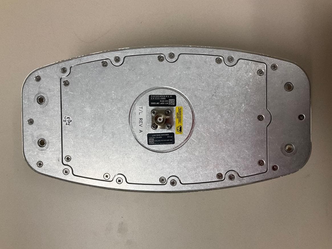
AJK8223587
Jan 23, 2023IRT-4200 SATCOM System
Equipment Class
TNB - Licensed Non-Broadcast Station Transmitter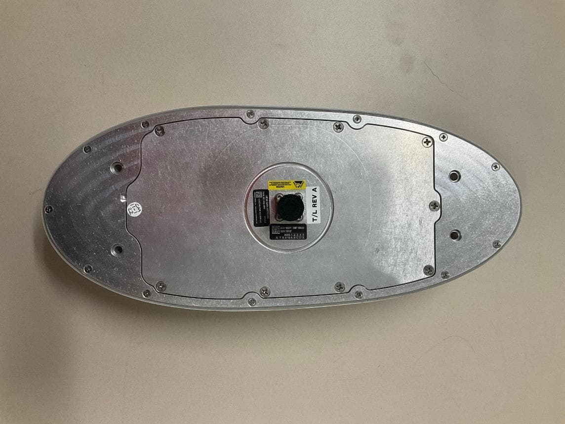
AJK8223586
Jan 23, 2023IRT-4400 SATCOM System
Equipment Class
TNB - Licensed Non-Broadcast Station Transmitter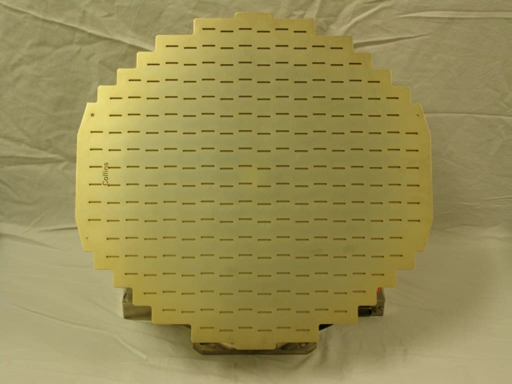
AJK8222259
Nov 11, 2015Weather Radar
Equipment Class
TNB - Licensed Non-Broadcast Station Transmitter
AJK8223132
May 20, 2015Information Management System
Equipment Class
DTS - Digital Transmission System
AJK8223075
Mar 04, 2013TCAS II Transmitter/Receiver
Equipment Class
TNB - Licensed Non-Broadcast Station Transmitter