AJK8222234HST-2120B
Rockwell Collins Inc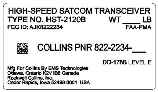
Click to zoom
Application Details
- Equipment Class
- TNB - Licensed Non-Broadcast Station Transmitter
- Date of Grant
- Jul 27, 2008
- Application Purpose
- Original Equipment
- Date of Application
- May 28, 2008
- Equipment Note
- HST-2120B
- Frequency Range
- 1626.50000000 - 1660.50000000
- Company
- Rockwell Collins Inc
- Country
- United States
Documents & Files
Document Text
Text extracted from the exhibit documents filed with the FCC. Open a document above to read the original.
Block Diagram
Page 1 of 7 Exhibit D Product Description NOTICE : The contents of this document are proprietary to Rockwell Collins, Inc. and shall not be disclosed, disseminated, copied, or used except for purposes expressly authorized in writing by Rockwell Collins, Inc. NOTICE : The technical data in this document (or file) is controlled for export under the Export Administration Regulations (EAR), 15 CFR Parts 730-774. Violations of these export laws may be subject to fines and penalties under the Export Administration Act. NOTICE : This document is a paper representation of the master data which is maintained in the Product Data Management (PDM) system. NOTICE : The following software was used to produce this document: Microsoft Word 2003 SP2 NOTICE : © Copyright 2008 Rockwell Collins, Inc. All rights reserved. Rockwell Collins, Inc. 400 Collins Rd. NE Cedar Rapids, Iowa 52498 CAGEC 4V792 HST-2110B, HST-2120B FCC Type Certification Report Rockwell Collins, Inc. - Proprietary Information Page 2 1 Exhibit D – Product Description 1.1 Overview The High Speed data Transceiver (HST), type numbers HST-2110B and HST-2120B are additional units designed to work with the SRT-2100B Satellite Data Unit (SDU). A complete SATCOM system consists of the following components: Table 1 - List of Equipment Type Number Name Manufacturer FCC ID SRT-2100B (3 channel version) Satellite Data Unit Rockwell Collins AJK8221785 High Gain Antenna System n/a various n/a HST-2110B or HST-2120B High Speed Data Transceiver EMS AJK8222232 or AJK8222234 The SRT-2100B requires software and High Power Amplifier modifications to support the addition of the HST-2110B or HST-2120B. These modifications will result in changes that affect previously submitted test data for SRT-2100. The SRT-2100B will require FCC Certification as a result of these changes. The changes necessary to add an HST-2110B or HST-2120B to the existing SRT-2100 System are highlighted in the outlined area of Figure 1 below: HST-2110B, HST-2120B FCC Type Certification Report Rockwell Collins, Inc. - Proprietary Information Page 3 Figure 1 - SRT-2100B System with HST 21X0B The HST-2110B or HST-2120B will add the INMARSAT SwiftBroadband service to the existing INMARSAT aeronautical services and Swift64 high speed service already supported by the SRT-2100 system. By incorporating the SwiftBroadband service from INMARSAT, the HST High-Speed Transceiver will provide up to 432 kilobits per second connectivity using the SAT-2100B antenna and high-power amplifier. The HST-2110B and HST-2120B transmit low level L-band signal to the SRT-2100B, which has a secondary input to its internal High Power Amplifier (HPA). The HPA is a broadband linear amplifier which simultaneously amplifies the classic Aero-H carriers generated internally to the SRT-2100B, as well as the L-band carrier(s) generated by the HST-2110B or HST-2120B. The HST-2110B and HST-2120B receivers are independent of the SRT-2100B. The output of the LNA/Diplexer typically passes through a passive L-band RF splitter and is routed to both the SRT-2100B and HST-2110B (or HST-2120B) receiver inputs. The HST supplies interfaces to Ethernet, ISDN and RS-232 which will provide real time passenger e-mail and Internet access as well as the high speed data applications such as real time cabin surveillance to the ground, file server, SwiftBroadband, Swift 64 and integrated information systems cockpit applications. HST-2110B, HST-2120B FCC Type Certification Report Rockwell Collins, Inc. - Proprietary Information Page 4 1.2 HST-2110B and HST-2120B Equipment Specifications Table 2 - Equipment Specifications CHARACTERISTIC SPECIFICATION Digital interface Crosstalk Bus High-speed ARINC 429 input and output Ethernet User Interface 10 Base T input and output ISDN User Interface 64 kbps ISDN Euro input and output (HST-2110B) 128 kbps ISDN Euro input and output (HST-2120B) RS-232 User MPDS Interface 115.2 kbps RS -232 input and output RS-232 Data Loader Port 115.2 kbps RS -232 input and output Input characteristics Frequency range 1525.0 to 1559.0 MHz Impedance 50 Ω nominal VSWR 2.0:1 max Signal input level -100 dBm to -60 dBm Output characteristics Frequency range 1626.5 to 1660.5 MHz Impedance 50 Ω nominal Load VSWR 2.0:1 operational, infinite, survival Output power -6.5 dBm to 22 dBm in 0.5 dB increments HST-2110B, HST-2120B FCC Type Certification Report Rockwell Collins, Inc. - Proprietary Information Page 5 1.3 HST Hardware Overview The HST product line consists of the following LRUs: • The HST-2110B, Collins Part Number 822-2232-020. This unit is designed to operate primary power of 115 VAC, 400Hz power source. It is similar to the previously Type Certified HST-2110 except that it contains new software that supports both Swift 64 and SwiftBroadband services. • The HST-2110B, Collins Part Number 822-2232-010. This unit is designed to operate with 28V DC power source. It is similar to the previously Type Certified HST-2110 except that it contains new software that supports both Swift 64 and SwiftBroadband services. • The HST-2120B, Collins Part Number 822-2234-010. This unit is designed to operate with 28V DC power source. It is similar to the previously Type Certified HST-2120 except that it contains new software that supports both Swift 64 and SwiftBroadband services This unit supports two simultaneous channels of Swift64 or one channel of SwiftBroadband. Figure 2 shows the major functional blocks of the HST-2110B (single channel), Figure 3 shows the major functional blocks of the HST-2120B (dual channel). Figure 2 - HST-2110B Block Diagram HST-2110B, HST-2120B FCC Type Certification Report Rockwell Collins, Inc. - Proprietary Information Page 6 Figure 3 - HST-2120B Block Diagram 1.4 Mechanical Both the HST-2110B and HST-2120B are housed in a 2-MCU-size unit with mounting requirements according to the ARINC 600 specification. The HST chassis is designed for either forced air or convection cooling. The front panel contains a data lo…
Text truncated - open the document above for the full version.
External Photos
Page 1 of 4 Exhibit C Equipment Photographs: External View NOTICE : The contents of this document are proprietary to Rockwell Collins, Inc. and shall not be disclosed, disseminated, copied, or used except for purposes expressly authorized in writing by Rockwell Collins, Inc. NOTICE : The technical data in this document (or file) is controlled for export under the Export Administration Regulations (EAR), 15 CFR Parts 730-774. Violations of these export laws may be subject to fines and penalties under the Export Administration Act. NOTICE : This document is a paper representation of the master data which is maintained in the Product Data Management (PDM) system. NOTICE : The following software was used to produce this document: Microsoft Word 2003 SP2 NOTICE : © Copyright 2008 Rockwell Collins, Inc. All rights reserved. Rockwell Collins, Inc. 400 Collins Rd. NE Cedar Rapids, Iowa 52498 CAGEC 4V792 HST-2110B, HST-2120B FCC Type Certification Report Rockwell Collins, Inc. - Proprietary Information Page 2 of 4 The following details the front panel nameplate proposed for the HST-2120B. A diagram depicting the nameplate location on the unit is also included. Figure 1 – Nameplate HST-2110B, HST-2120B FCC Type Certification Report Rockwell Collins, Inc. - Proprietary Information Page 3 of 4 Figure 2 – HST-2120B Front Panel showing nameplate location HST-2110B, HST-2120B FCC Type Certification Report Rockwell Collins, Inc. - Proprietary Information Page 4 of 4 Figure 3 – HST-21X0 Assembly
ID Label/Location Info
Page 1 of 3 Exhibit A Nameplate Label Drawings NOTICE : The contents of this document are proprietary to Rockwell Collins, Inc. and shall not be disclosed, disseminated, copied, or used except for purposes expressly authorized in writing by Rockwell Collins, Inc. NOTICE : The technical data in this document (or file) is controlled for export under the Export Administration Regulations (EAR), 15 CFR Parts 730-774. Violations of these export laws may be subject to fines and penalties under the Export Administration Act. NOTICE : This document is a paper representation of the master data which is maintained in the Product Data Management (PDM) system. NOTICE : The following software was used to produce this document: Microsoft Word 2003 SP2 NOTICE : © Copyright 2008 Rockwell Collins, Inc. All rights reserved. Rockwell Collins, Inc. 400 Collins Rd. NE Cedar Rapids, Iowa 52498 CAGEC 4V792 HST-2110B, HST-2120B FCC Type Certification Report Rockwell Collins, Inc. - Proprietary Information Page 2 of 3 Exhibit A – Nameplate Drawing and Location The following details the front panel nameplate proposed for the HST-2120B. A diagram depicting the nameplate location on the unit is also included. Figure 1 – Nameplate HST-2110B, HST-2120B FCC Type Certification Report Rockwell Collins, Inc. - Proprietary Information Page 3 of 3 Figure 2 – HST-2120B Front Panel showing nameplate location
Test Report
Exhibit F3 Field Strength of Spurious Radiation NOTICE: The contents of this document are proprietary to Rockwell Collins, Inc. and shall not be disclosed, disseminated, copied, or used except for purposes expressly authorized in writing by Rockwell Collins, Inc. NOTICE: The technical data in this document (or file) is controlled for export under the Export Administration Regulations (EAR), 15 CFR Parts 730-774. Violations of these export laws may be subject to fines and penalties under the Export Administration Act. NOTICE: The following software was used to produce this document: Microsoft Word 2003 SP2 NOTICE: © Copyright 2008 Rockwell Collins, Inc. All rights reserved. Rockwell Collins, Inc. 400 Collins Rd. NE Cedar Rapids, Iowa 52498 CAGEC 4V792 Page 1 HST-2110B, HST-2120B FCC Type Certification Report 1 Exhibit F3 – Field Strength of Spurious Radiation The measurements in this section have been resubmitted from Rockwell Collins’ previous FCC Equipment Authorization Application for HST-2110 (FCC ID: AJK8222231) and HST-2120 (FCC ID: AJK8222233). The internal hardware of the HST-2110B and HST-2120B are the same as the HST-2110 and HST-2120. Although some RF emission differences are expected (caused by the new RF waveform to support the SwiftBroadband service), these differences are present at the transmitter output terminal and not from spurious radiation exiting the chassis of the HST-2110B and HST-2120B. Transmitter emission results are provided elsewhere in this report. Therefore, the field strength of spurious radiation test results are not impacted by the addition of SwiftBroadband. The test results in this section have been extracted from the report documenting the testing of the equipment to RTCA DO-160D, Section 21, Category M. This test measures the emissions radiated from the equipment case and any interconnecting cables. Rockwell Collins, Inc. - Proprietary Information Page 2 of 8 HST-2110B, HST-2120B FCC Type Certification Report Figure 1 - Radiated Emissions - Monopole Antenna 2-30 MHz Figure 2 - Radiated Emissions - Horizontal Bicon Antenna 30-200 MHz Rockwell Collins, Inc. - Proprietary Information Page 3 of 8 HST-2110B, HST-2120B FCC Type Certification Report Figure 3 - Radiated Emissions - Vertical Bicon Antenna 30-200 MHz Figure 4 - Radiated Emissions - Horizontal Horn Antenna 200-1000 MHz Rockwell Collins, Inc. - Proprietary Information Page 4 of 8 HST-2110B, HST-2120B FCC Type Certification Report Figure 5 - Radiated Emissions - Vertical Horn Antenna 200-1000 MHz Figure 6 - Radiated Emissions - Horizontal Horn Antenna 1000-3000 MHz Rockwell Collins, Inc. - Proprietary Information Page 5 of 8 HST-2110B, HST-2120B FCC Type Certification Report Figure 7- Radiated Emissions - Vertical Horn Antenna 1000-3000 MHz Figure 8 - Radiated Emissions - Horizontal Horn Antenna 1000-18000 MHz Rockwell Collins, Inc. - Proprietary Information Page 6 of 8 HST-2110B, HST-2120B FCC Type Certification Report Figure 9 - Radiated Emissions - Vertical Horn Antenna 1000-18000 MHz Figure 10 - Radiated Emissions Test Setup – MPB Rockwell Collins, Inc. - Proprietary Information Page 7 of 8 HST-2110B, HST-2120B FCC Type Certification Report Figure 11 - Radiated Emissions Test Setup – MPB Figure 12 - Radiated Emissions Test Setup - MPB Rockwell Collins, Inc. - Proprietary Information Page 8 of 8
Test Setup Photos
Page 1 Exhibit G Test Setup Photos NOTICE : The contents of this document are proprietary to Rockwell Collins, Inc. and shall not be disclosed, disseminated, copied, or used except for purposes expressly authorized in writing by Rockwell Collins, Inc. NOTICE : The technical data in this document (or file) is controlled for export under the Export Administration Regulations (EAR), 15 CFR Parts 730-774. Violations of these export laws may be subject to fines and penalties under the Export Administration Act. NOTICE : This document is a paper representation of the master data which is maintained in the Product Data Management (PDM) system. NOTICE : The following software was used to produce this document: Microsoft Word 2003 SP2 NOTICE : © Copyright 2008 Rockwell Collins, Inc. All rights reserved. Rockwell Collins, Inc. 400 Collins Rd. NE Cedar Rapids, Iowa 52498 CAGEC 4V792 HST-2110B, HST-2120B FCC Type Certification Report Rockwell Collins, Inc. - Proprietary Information Page 2 of 3 Figure 1 - Radiated Emissions Test Setup – MPB Figure 2 - Radiated Emissions Test Setup – MPB HST-2110B, HST-2120B FCC Type Certification Report Rockwell Collins, Inc. - Proprietary Information Page 3 of 3 Figure 3 - Radiated Emissions Test Setup - MPB
Contact Information
Applicant
Thomas A. Voltero(Director & Senior Counsel)
Technical Specifications
| # | Rule Parts | Frequency Range | Power Output | Emission | Tolerance |
|---|---|---|---|---|---|
| 19 | 87 | 1.63 GHz - 1.66 GHz | 79.00 mW | 200KG7W | 480 Hz |
Other Applications from Rockwell Collins Inc
AJK8223587
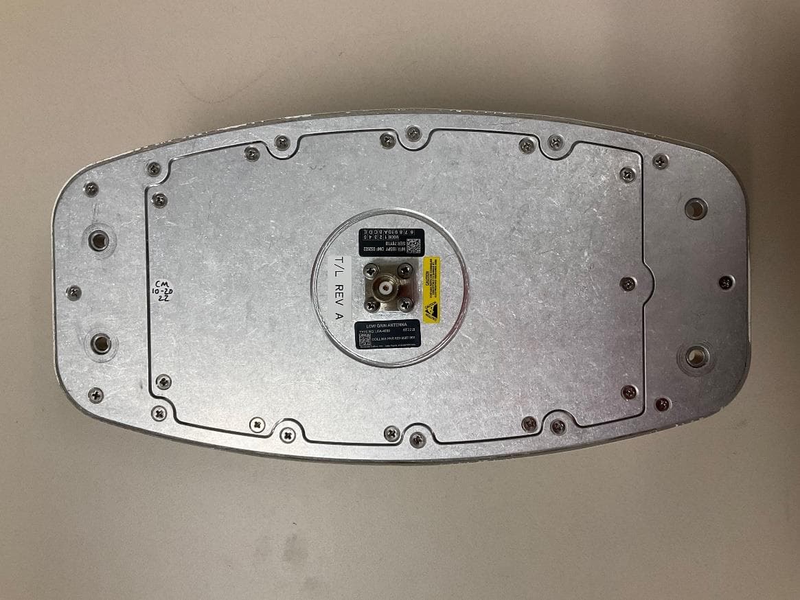
Jan 23, 2023IRT-4200 SATCOM System
Equipment Class
TNB - Licensed Non-Broadcast Station Transmitter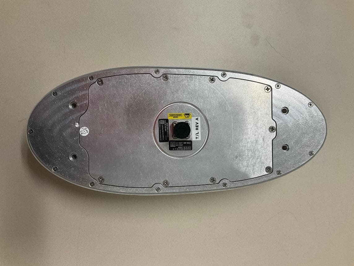
AJK8223586
Jan 23, 2023IRT-4400 SATCOM System
Equipment Class
TNB - Licensed Non-Broadcast Station Transmitter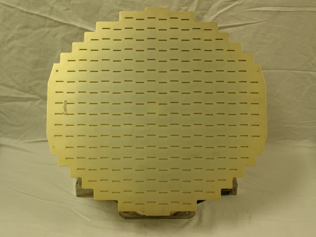
AJK8222259
Nov 11, 2015Weather Radar
Equipment Class
TNB - Licensed Non-Broadcast Station Transmitter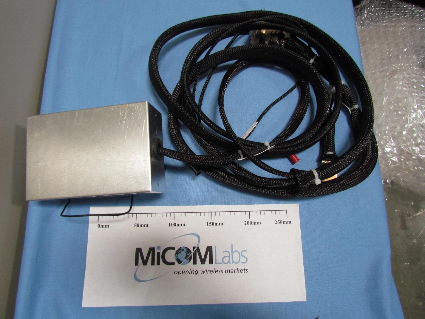
AJK8223132
May 20, 2015Information Management System
Equipment Class
DTS - Digital Transmission System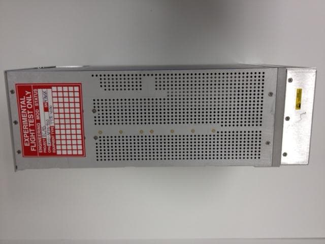
AJK8223075
Mar 04, 2013TCAS II Transmitter/Receiver
Equipment Class
TNB - Licensed Non-Broadcast Station Transmitter