ALZM2PMV-PAC
Multi-Voice Radio LLC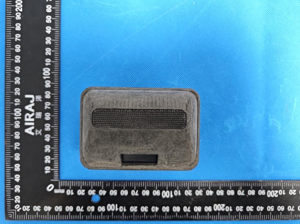
Click to zoom
Application Details
- Equipment Class
- DSS - Part 15 Spread Spectrum Transmitter
- Date of Grant
- Aug 30, 2023
- Application Purpose
- Original Equipment
- Date of Application
- Aug 30, 2023
- Equipment Note
- MV-PAC
- Frequency Range
- 902.82000000 - 926.90000000
- Company
- Multi-Voice Radio LLC
- Country
- United States
Documents & Files
Document Text
Text extracted from the exhibit documents filed with the FCC. Open a document above to read the original.
Users Manual
Use Included USB-C cables and wall charger Plug USB-C cable into the Bottom of the PAC. There will be a "click" when fully inserted. The PAC is charging when • Pulsing Red. • Pulsing Red and Green Solid Green Light indicates Charge is complete Thing to check: • One Unit has a "M" in the status area. Only one PAC has the "M". • Stay within line of sight with all Units. • Check that battery level is above 10%. • Bend the mic boom so it is rotated down far enough to activate the mic. Solutions: 1) Turn off the Unit with the issue. Turn it back on again. This can be done when the system is in use. 2) Reset the entire system. Make sure all Units are off before turning back on. Product Description The Multi-Voice Radio combines conference communication with wireless radio. This full duplex system allows hands free communication on a secure signal with a easy to use design Measurements Length: 3.5 in Height: 1.4 in Width: 2.4 in Weight: 20 oz Signal Frequency: 902-928 MHz Frequency Hopping Spread Spectrum Output Power: Over 500mW Range: Up To 3/4 Mile Line of Sight Proprietary Encryption Battery 10 Hour Operation Temp: -20c +60c Rechargeable Lithium-polymer 1600 mAh UL 1642, Compliance to US/CANADA This device complies with part 15 of the FCC rules. Operation is subject to the following two conditions: (1) This device does not cause harmful interference, and (2) this device must accept any interference received, including interference that may cause undesired operation. Note: This e quipment has been tested and found to comply with the limits for a Class B digital device, pursuant to Part 15 of the FCC Rules. These limits are designed to provide reasonable protection against harmful interference in a residential installa tion. This equipment g enerates, uses and can radiate radio frequency energy and, if not installed and used in accordance with the instructions, may cause harmful inter ference to radio communications. However, there is n o guarantee that interference will not occur in a particular installa tion. If this equipment does cause harmful interference to radio or television recep tion, w hich can be determined by turning the equipment off and on, the user is en couraged to try to correct the interference by one or more of the following measures: • Reorient or relocate the receiving antenna. • Increase the separation between the equipment and receiver. • Connect the equipment into an outlet on a circuit different from that to which the re ceiver is connected. • Consult the dealer or an experienced radio/TV technician for help. Warning: Changes or modifications made to this equipment not expressly approved by Multi-Voice Radio may void the user's authority to operate the equipment. This Class B digital device complies with Canadian ICES-003. Cet appareil numerique de la classe Best conforme a la norme NMB-003 du Canada. Le present appareil est conforme aux CNR d'lndustrie Canada applicables aux appa reils radio exempts de licence. L'exploitation est autorisee aux deux conditions suiva ntes : (1) l'appareil ne doit pas produire de brouillage, et (2) l'utilisateur de l'appareil doit accepter tout brouillage radioelectrique subi, meme si le brouillage est suscepti ble d'en compromettre le foncti onnement. FCC ID: ALZM2P IC: Model : MV2P x:z. ->))..., ·-· MULTIVOICE Standard Quickstart Guide MV-PAC Beltpack & Headset Industrial/Sports BUTTONS usb-c MUL TIVOICE, MV-ONE,and the MULTIVOICE marks and logos are each trademarks of MUL TIVOICE. (800)-604-0737 I www.MULTIVOICE.com I © MUL TIVOICE 2016 I R1 .0 2023 FCC Caution This device complies with part 15 of the FCC Rules. Operation is subject to the following two conditions: (1) This device may not cause harmful interference, and (2) this device must accept any interference received, including interference that may cause undesired operation. Any Changes or modifications not expressly approved by the party responsible for compliance could void the user's authority to operate the equipment. Note: This equipment has been tested and found to comply with the limits for a Class B digital device, pursuant to part 15 of the FCC Rules. These limits are designed to provide reasonable protection against harmful interference in a residential installation. This equipment generates uses and can radiate radio frequency energy and, if not installed and used in accordance with the instructions, may cause harmful interference to radio communications. However, there is no guarantee that interference will not occur in a particular installation. If this equipment does cause harmful interference to radio or television reception, which can be determined by turning the equipment off and on, the user is encouraged to try to correct the interference by one or more of the following measures: - Reorient or relocate the receiving antenna. - Increase the separation between the equipment and receiver. - Connect the equipment into an outlet on a circuit different from that to which the receiver is connected. - Consult the dealer or an experienced radio/TV technician for help. The device has been evaluated to meet general RF exposure requirement. The device can be used in portable exposure condition without restriction. FCC RF Exposure Information and Statement The SAR limit of USA (FCC) is 1.6 W/kg averaged over one gram of tissue. Device types MV-Pak(FCC ID: ALZM2P) has also been tested against this SAR limit. The highest SAR value reported under this standard during product certification for use at the body is 1.546W/kg. This device was tested for typical body-worn operations with the back of the handset kept 0mm from the body. To maintain compliance with FCC RF exposure requirements, use accessories that maintain a 0mm separation distance between the user's body and the back of the handset. The use of belt clips, holsters and similar accessories should not contain metallic components in its assembly. The use of accessories that do not satisfy these requirements…
Text truncated - open the document above for the full version.
Attestation Statements
Multi-Voice Radio LLC U.S. Agent Designation for Service of Process (Applicant and U.S. Agent are Separate Parties) TO: Federal Communications Commission Authorization and Evaluation Division 7435 Oakland Mills Road Columbia, MD 21046, USA ATTENTION: FCC Certification – Section 2.911(d)(7) Information Designated U.S. Agent Company Name: Multi-Voice Radio LLC FRN: 0021402482 Contact Name: Dustin Fraser Address: 266e 900s, Mapleton, Utah, United States 84664 Telephone No: 801-636-9149 Email: [email protected] This letter is to confirm that we (Multi-Voice Radio LLC) have accepted the responsibility to act as the Designated U.S. Agent for Service of Process as required by section 47 CFR 2.911(d)(7) on behalf of the Applicant noted below. U.S. Agent Signature: Date: 2023-08-22 Signed by (Printed Name/Title): Dustin Fraser /Vice President The Applicant acknowledges that they must maintain an agent for no less than one year after terminating all marketing and importation OR the conclusion of any Commission-related proceeding involving the equipment. The applicant further acknowledges their responsibility to inform the FCC whenever the Designated U.S. Agent information above changes. Applicant Company name: Multi-Voice Radio LLC FCC ID: ALZM2P Contact Name: Dustin Fraser Address: 266e 900s, Mapleton, Utah, United States 84664 Telephone No: 801-636-9149 Email: [email protected] Applicant Signature: Date: 2023-08-22 Signed by (Printed Name/Title): Dustin Fraser /Vice President
Attestation Statements
Multi-Voice Radio LLC 2023.08.22 Eurofins Electrical and Electronic Testing NA, Inc. 914 West Patapsco Avenue Baltimore, MD 21230 RE: Attestation Statements Part 2.911(d)(5)(i) request for FCC ID: ALZM2P [Multi-Voice Radio LLC] (“the applicant”) certifies that the equipment for which authorization is sought is not “covered” equipment prohibited from receiving an equipment authorization pursuant to section 2.903 of the FCC rules. Sincerely, (Applicant signature) (Applicant printed name) Dustin Fraser Multi-Voice Radio LLC 2023.08.22 Eurofins Electrical and Electronic Testing NA, Inc. 914 West Patapsco Avenue Baltimore, MD 21230 RE: Attestation Statements Part 2.911(d)(5)(ii) request for FCC ID: ALZM2P [Multi-Voice Radio LLC] (“the applicant”) certifies that, as of the date of the filing of the application, the applicant is not identified on the Covered List as an entity producing “covered” equipment. Sincerely, (Applicant signature) (Applicant printed name) Dustin Fraser
Cover Letter(s)
Multi-Voice Radio LLC 2023.08.22 Eurofins Electrical and Electronic Testing NA, Inc. 914 W. Patapsco Avenue Baltimore, MD 21230 USA RE: CONFIDENTIALITY REQUEST FOR EUT NAME: MV-PAC Trademark: N/A MODEL : MV2P FCC ID : ALZM2P To Whom It May Concern: This letter serves as an official request for confidentiality under sections 0.457 and 0.459 of CFR 47. We have requested that the - Block Diagram - Schematics - Operational Description required to be submitted with this application be permanently withheld from public review. The above materials contain trade secrets and proprietary information not customarily released to the public. The public disclosure of these materials may be harmful to the applicant and provide unjustified benefits to its competitors. Please contact me if there is any information you may need. Sincerely, Client’s signature: Client’s name / title : Dustin Fraser / Vice President Contact information / address: 266e 900s, Mapleton, Utah, United States 84664
Cover Letter(s)
Multi-Voice Radio LLC 2023.08.22 Eurofins Electrical and Electronic Testing NA, Inc. 914 W. Patapsco Avenue Baltimore, MD 21230 USA RE: LETTER OF AGENT AUTHORIZATION To Whom It May Concern: We, the undersigned, hereby authorize Shenzhen BCTC Testing Co., Ltd to act on our behalf in all matters relating to application for equipment authorization, including the signing of all documents relating to these matters. We also hereby certify that no party to the application authorized hereunder is subject to the denial of benefits, including FCC benefits, pursuant to Section 5301 of the Anti-Drug Abuse Act of 1988, 21 U.S.C.853(a). This agreement expires one year from the current date. Sincerely, Client’s signature: Client’s name / title : Dustin Fraser / Vice President Contact information / address: 266e 900s, Mapleton, Utah, United States 84664
External Photos
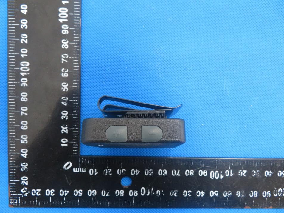
Appendix Photographs External Photos
ID Label/Location Info
Size:20*10mm MV-PAC FCC ID: ALZM2P Label location
Internal Photos
Internal Photos Antenna Antenna Antenna
RF Exposure Info
No.:BCTC/RF-EMC-005 Page 1 of 83 Edition:B.0 TEST REPORT Shenzhen BCTC Testing Co., Ltd. Report No.: BCTC2308023906E Applicant: Multi-Voice Radio LLC Product Name: MV-PAC Model/Type Ref.: MV2P Tested Date: 2023-08-10 to 2023-08-18 Issued Date: 2023-08-22 Report No:BCTC2308023906E No.:BCTC/RF-EMC-005 Page 2 of 83 Edition:B.0 FCC ID: ALZM2P The test report is effective only with both signature and specialized stamp. This result(s) shown in this report refer only to the sample(s) tested. Without written approval of Shenzhen BCTC Testing Co., Ltd, this report can’t be reproduced except in full. The tested sample(s) and the sample information are provided by the client. Product Name: MV-PAC Trademark: N/A Model/Type Ref.: MV2P Applicant: Multi-Voice Radio LLC Address: 266e 900s, Mapleton, Utah, United States 84664 Manufacturer: Multi-Voice Radio LLC Address: 266e 900s, Mapleton, Utah, United States 84664 Prepared By: Shenzhen BCTC Testing Co., Ltd. Address: 1-2/F., Building B, Pengzhou Industrial Park, No.158, Fuyuan 1st Road, Zhancheng, Fuhai Subdistrict, Bao'an District, Shenzhen, Guangdong, China Sample Received Date: 2023-06-14 Sample tested Date: 2023-08-10 to 2023-08-18 Issue Date: 2023-08-22 SAR Max. Values is: 1.308 W/kg (1g) for Body Test Standards: IEEE Std C95.1, 2019/ IEEE Std 1528™-2013/FCC Part 2.1093 Test Results: PASS Remark: This is SAR test report Tested by: Approved by: Hubery Cai/Project Handler Zero Zhou/Reviewer Report No:BCTC2308023906E No.:BCTC/RF-EMC-005 Page 3 of 83 Edition:B.0 Table Of Content Test Report Declaration Page 1. Version .................................................................................................................. 5 2. Test Standards ...................................................................................................... 6 3. Test Summary ....................................................................................................... 7 4. SAR Limits............................................................................................................. 8 5. Measurement Uncertainty ..................................................................................... 9 6. Product Information and Test Setup .................................................................... 10 6.1 Product Information ............................................................................................... 10 6.2 Test Setup Configuration ....................................................................................... 11 6.3 Support Equipment ................................................................................................ 11 6.4 Test Environment .................................................................................................. 11 7. Test Facility and Test Instrument Used ............................................................... 12 7.1 Test Facility ........................................................................................................... 12 7.2 Test Instrument Used ............................................................................................ 12 8. Specific Absorption Rate (SAR) .......................................................................... 14 8.1 Introduction ............................................................................................................ 14 8.2 SAR Definition ....................................................................................................... 14 9. SAR Measurement System ................................................................................. 15 9.1 The Measurement System ..................................................................................... 15 9.2 Probe ..................................................................................................................... 15 9.3 Probe Calibration Process ..................................................................................... 17 9.4 Phantom ................................................................................................................ 18 9.5 Device Holder ........................................................................................................ 18 10. Tissue Simulating Liquids .................................................................................... 19 10.1 Composition of Tissue Simulating Liquid ............................................................. 19 10.2 Limit ..................................................................................................................... 20 10.3 Tissue Calibration Result ..................................................................................... 21 11. System Check ..................................................................................................... 22 11.1 Purpose of System Performance Check .............................................................. 22 11.2 System Setup ...................................................................................................... 22 11.3 Validation Results ................................................................................................ 23 12. EUT Testing Position ........................................................................................... 24 Body-worn Position ...................................................................................................... 24 13. SAR Measurement Procedures ........................................................................... 25 13.1 Measurement Procedures ................................................................................... 25 13.2 Spatial Peak SAR Evaluation .............................................................................. 25 13.3 Area & Zoom Scan Procedures ........................................................................... 26 13.4 Volume Scan Procedures ................................................................................…
Text truncated - open the document above for the full version.
RF Exposure Info
Report No:BCTC2308023906E No.:BCTC/RF-EMC-005 Page 61 of 83 Edition:B.0 Report No:BCTC2308023906E No.:BCTC/RF-EMC-005 Page 62 of 83 Edition:B.0 Report No:BCTC2308023906E No.:BCTC/RF-EMC-005 Page 63 of 83 Edition:B.0 Report No:BCTC2308023906E No.:BCTC/RF-EMC-005 Page 64 of 83 Edition:B.0 Report No:BCTC2308023906E No.:BCTC/RF-EMC-005 Page 65 of 83 Edition:B.0 Report No:BCTC2308023906E No.:BCTC/RF-EMC-005 Page 66 of 83 Edition:B.0 Report No:BCTC2308023906E No.:BCTC/RF-EMC-005 Page 67 of 83 Edition:B.0 Report No:BCTC2308023906E No.:BCTC/RF-EMC-005 Page 68 of 83 Edition:B.0 Report No:BCTC2308023906E No.:BCTC/RF-EMC-005 Page 69 of 83 Edition:B.0 Report No:BCTC2308023906E No.:BCTC/RF-EMC-005 Page 70 of 83 Edition:B.0 Report No:BCTC2308023906E No.:BCTC/RF-EMC-005 Page 71 of 83 Edition:B.0 Report No:BCTC2308023906E No.:BCTC/RF-EMC-005 Page 72 of 83 Edition:B.0 Report No:BCTC2308023906E No.:BCTC/RF-EMC-005 Page 73 of 83 Edition:B.0 Report No:BCTC2308023906E No.:BCTC/RF-EMC-005 Page 74 of 83 Edition:B.0 Report No:BCTC2308023906E No.:BCTC/RF-EMC-005 Page 75 of 83 Edition:B.0 Report No:BCTC2308023906E No.:BCTC/RF-EMC-005 Page 76 of 83 Edition:B.0 Report No:BCTC2308023906E No.:BCTC/RF-EMC-005 Page 77 of 83 Edition:B.0 Report No:BCTC2308023906E No.:BCTC/RF-EMC-005 Page 78 of 83 Edition:B.0 Report No:BCTC2308023906E No.:BCTC/RF-EMC-005 Page 79 of 83 Edition:B.0 Report No:BCTC2308023906E No.:BCTC/RF-EMC-005 Page 80 of 83 Edition:B.0 17. EUT Photographs EUT Front View EUT Back View Report No:BCTC2308023906E No.:BCTC/RF-EMC-005 Page 81 of 83 Edition:B.0 Antenna View BT ANT-A BT ANT-B RFID ANT Report No:BCTC2308023906E No.:BCTC/RF-EMC-005 Page 82 of 83 Edition:B.0 18. EUT Test Setup Photographs Body mode Exposure Conditions Test distance: 0mm Back Front Report No:BCTC2308023906E No.:BCTC/RF-EMC-005 Page 83 of 83 Edition:B.0 STATEMENT 1. The equipment lists are traceable to the national reference standards. 2. The test report can not be partially copied unless prior written approval is issued from our lab. 3. The test report is invalid without stamp of laboratory. 4. The test report is invalid without signature of person(s) testing and authorizing. 5. The test process and test result is only related to the Unit Under Test. 6. The quality system of our laboratory is in accordance with ISO/IEC17025. 7. If there is any objection to report, the client should inform issuing laboratory within 15 days from the date of receiving test report. Address: 1-2/F., Building B, Pengzhou Industrial Park, No.158, Fuyuan 1st Road, Zhancheng, Fuhai Subdistrict, Bao’an District, Shenzhen, Guangdong, China TEL:400-788-9558 1) C.: 518103 FAX:0755-33229357 Website:http://www.chnbctc.com E-Mail:[email protected] ※※※※※ END ※※※※※
Test Report
No.:BCTC/RF-EMC-007 Page: 1 of 81 Edition:B.0 TEST REPORT Shenzhen BCTC Testing Co., Ltd. Report No.: BCTC2306157018-1E Applicant: Multi-Voice Radio LLC Product Name: MV-PAC Model/Type reference: MV2P Tested Date: 2023-06-14 to 2023-08-04 Issued Date: 2023-08-04 Report No.: BCTC2306157018-1E No.:BCTC/RF-EMC-007 Page: 2 of 81 Edition:B.0 FCC ID: ALZM2P The test report is effective only with both signature and specialized stamp. This result(s) shown in this report refer only to the sample(s) tested. Without written approval of Shenzhen BCTC Testing Co., Ltd, this report can’t be reproduced except in full. The tested sample(s) and the sample information are provided by the client. Product Name: MV-PAC Trademark: N/A Model/Type Reference: MV2P Prepared For: Multi-Voice Radio LLC Address: 266e 900s, Mapleton, Utah, United States 84664 Manufacturer: Multi-Voice Radio LLC Address: 266e 900s, Mapleton, Utah, United States 84664 Prepared By: Shenzhen BCTC Testing Co., Ltd. Address: 1-2/F., Building B, Pengzhou Industrial Park, No.158, Fuyuan 1st Road, Zhancheng, Fuhai Subdistrict, Bao'an District, Shenzhen, Guangdong, China Sample Received Date: 2023-06-14 Sample tested Date: 2023-06-14 to 2023-08-04 Issue Date: 2023-08-04 Report No.: BCTC2306157018-1E Test Standards FCC Part15.247 ANSI C63.10-2013 Test Results PASS Remark: This is Bluetooth Classic radio test report, the Bluetooth IC tested is CSR8670. Tested by: Approved by: Lei Chen/Project Handler Zero Zhou/Reviewer Report No.: BCTC2306157018-1E No.:BCTC/RF-EMC-007 Page: 3 of 81 Edition:B.0 Table Of Content Test Report Declaration Page 1. Version .................................................................................................................. 5 2. Test Summary ....................................................................................................... 6 3. Measurement Uncertainty ..................................................................................... 7 4. Product Information And Test Setup ..................................................................... 8 4.1 Product Information ............................................................................................... 8 4.2 Test Setup Configuration ...................................................................................... 8 4.3 Support Equipment ............................................................................................... 9 4.4 Channel List .......................................................................................................... 9 4.5 Test Mode ........................................................................................................... 10 4.6 Table Of Parameters Of Text Software Setting ................................................... 10 5. Test Facility And Test Instrument Used ............................................................... 11 5.1 Test Facility ......................................................................................................... 11 5.2 Test Instrument Used .......................................................................................... 11 6. Conducted Emissions .......................................................................................... 13 6.1 Block Diagram Of Test Setup .............................................................................. 13 6.2 Limit .................................................................................................................... 13 6.3 Test procedure .................................................................................................... 13 6.4 EUT operating Conditions ................................................................................... 13 6.5 Test Result .......................................................................................................... 14 7. Radiated emissions ............................................................................................. 16 7.1 Block Diagram Of Test Setup .............................................................................. 16 7.2 Limit .................................................................................................................... 17 7.3 Test procedure .................................................................................................... 18 7.4 EUT operating Conditions ................................................................................... 19 7.5 Test Result .......................................................................................................... 19 8. Radiated Band Emission Measurement And Restricted Bands Of Operation ..... 25 8.1 Block Diagram Of Test Setup .............................................................................. 25 8.2 Limit .................................................................................................................... 25 8.3 Test procedure .................................................................................................... 26 8.4 EUT operating Conditions ................................................................................... 26 8.5 Test Result .......................................................................................................... 27 9. Spurious RF Conducted Emissions ..................................................................... 28 9.1 Block Diagram Of Test Setup .............................................................................. 28 9.2 Limit .................................................................................................................... 28 9.3 Test procedure .................................................................................................... 28 9.4 Test Result .......................................................................................................... 29 10. 20 dB Bandwidth ..................................................................................…
Text truncated - open the document above for the full version.
Test Report
Report No.: BCTC2306157018-1E No.:BCTC/RF-EMC-007 Page: 55 of 81 Edition:B.0 -20dB Bandwidth NVNT 3-DH1 2480MHz Report No.: BCTC2306157018-1E No.:BCTC/RF-EMC-007 Page: 56 of 81 Edition:B.0 11. Maximum Peak Output Power 11.1 Block Diagram Of Test Setup 11.2 Limit FCC Part15 (15.247) , Subpart C Section Test Item Limit Frequency Range (MHz) Result 15.247(b)(1) Peak Output Power 0.125 watt or 21dBm 2400-2483.5 PASS 11.3 Test procedure 1. Remove the antenna from the EUT and then connect a low RF cable from the antenna port to the spectrum. 2. Set the spectrum analyzer: RBW = 3MHz. VBW = 3MHz. Sweep = auto; Detector Function = Peak. 3. Keep the EUT in transmitting at lowest, medium and highest channel individually. Record the max value. 11.4 Test Result Condition Mode Frequency (MHz) Conducted Power (dBm) Limit (dBm) Verdict NVNT 1-DH1 2402 7.79 21 Pass NVNT 1-DH1 2441 8.06 21 Pass NVNT 1-DH1 2480 8.12 21 Pass NVNT 2-DH1 2402 6.22 21 Pass NVNT 2-DH1 2441 6.92 21 Pass NVNT 2-DH1 2480 7.11 21 Pass NVNT 3-DH1 2402 6.62 21 Pass NVNT 3-DH1 2441 7.2 21 Pass NVNT 3-DH1 2480 7.38 21 Pass Report No.: BCTC2306157018-1E No.:BCTC/RF-EMC-007 Page: 57 of 81 Edition:B.0 Test Graphs Power NVNT 1-DH1 2402MHz Power NVNT 1-DH1 2441MHz Report No.: BCTC2306157018-1E No.:BCTC/RF-EMC-007 Page: 58 of 81 Edition:B.0 Power NVNT 1-DH1 2480MHz Power NVNT 2-DH1 2402MHz Report No.: BCTC2306157018-1E No.:BCTC/RF-EMC-007 Page: 59 of 81 Edition:B.0 Power NVNT 2-DH1 2441MHz Power NVNT 2-DH1 2480MHz Report No.: BCTC2306157018-1E No.:BCTC/RF-EMC-007 Page: 60 of 81 Edition:B.0 Power NVNT 3-DH1 2402MHz Power NVNT 3-DH1 2441MHz Report No.: BCTC2306157018-1E No.:BCTC/RF-EMC-007 Page: 61 of 81 Edition:B.0 Power NVNT 3-DH1 2480MHz Report No.: BCTC2306157018-1E No.:BCTC/RF-EMC-007 Page: 62 of 81 Edition:B.0 12. Hopping Channel Separation 12.1 Block Diagram Of Test Setup 12.2 Limit Frequency hopping systems shall have hopping channel carrier frequencies separated by a minimum of 25 kHz or the 20 dB bandwidth of the hopping channel, whichever is greater. Alternatively, frequency hopping systems operating in the 2400-2483.5 MHz band may have hopping channel carrier frequencies that are separated by 25 kHz or two-thirds of the 20 dB bandwidth of the hopping channel, whichever is greater, provided the systems operate with an output power no greater than 0.125W. 12.3 Test procedure 1. Remove the antenna from the EUT and then connect a low RF cable from the antenna port to the spectrum. 2. Set the spectrum analyzer: RBW = 30kHz. VBW = 100kHz , Span = 2.0MHz. Sweep = auto; Detector Function = Peak. Trace = Max hold. 3. Allow the trace to stabilize. Use the marker-delta function to determine the separation between the peaks of the adjacent channels. The limit is specified in one of the subparagraphs of this Section Submit this plot. 12.4 Test Result Condition Mode Hopping Freq1 (MHz) Hopping Freq2 (MHz) HFS (MHz) Limit (MHz) Verdict NVNT 1-DH1 2401.976 2402.974 0.998 0.819 Pass NVNT 1-DH1 2441.008 2442.006 0.998 0.853 Pass NVNT 1-DH1 2479.008 2480.012 1.004 0.828 Pass NVNT 2-DH1 2402.014 2403.012 0.998 0.864 Pass NVNT 2-DH1 2441.006 2442.008 1.002 0.821 Pass NVNT 2-DH1 2479.01 2480.012 1.002 0.812 Pass NVNT 3-DH1 2402.01 2403.014 1.004 0.801 Pass NVNT 3-DH1 2441.004 2442.012 1.008 0.797 Pass NVNT 3-DH1 2479.01 2480.012 1.002 0.801 Pass Report No.: BCTC2306157018-1E No.:BCTC/RF-EMC-007 Page: 63 of 81 Edition:B.0 Test Graphs CFS NVNT 1-DH1 2402MHz CFS NVNT 1-DH1 2441MHz Report No.: BCTC2306157018-1E No.:BCTC/RF-EMC-007 Page: 64 of 81 Edition:B.0 CFS NVNT 1-DH1 2480MHz CFS NVNT 2-DH1 2402MHz Report No.: BCTC2306157018-1E No.:BCTC/RF-EMC-007 Page: 65 of 81 Edition:B.0 CFS NVNT 2-DH1 2441MHz CFS NVNT 2-DH1 2480MHz Report No.: BCTC2306157018-1E No.:BCTC/RF-EMC-007 Page: 66 of 81 Edition:B.0 CFS NVNT 3-DH1 2402MHz CFS NVNT 3-DH1 2441MHz Report No.: BCTC2306157018-1E No.:BCTC/RF-EMC-007 Page: 67 of 81 Edition:B.0 CFS NVNT 3-DH1 2480MHz Report No.: BCTC2306157018-1E No.:BCTC/RF-EMC-007 Page: 68 of 81 Edition:B.0 13. Number Of Hopping Frequency 13.1 Block Diagram Of Test Setup 13.2 Limit Frequency hopping systems in the 2400-2483.5 MHz band shall use at least 15 channels. 13.3 Test procedure 1. Remove the antenna from the EUT and then connect a low RF cable from the antenna port to the spectrum. 2. Set the spectrum analyzer: RBW = 100kHz. VBW = 300kHz. Sweep = auto; Detector Function = Peak. Trace = Max hold. 3. Allow the trace to stabilize. It may prove necessary to break the span up to sections. in order to clearly show all of the hopping frequencies. The limit is specified in one of the subparagraphs of this Section. 4. Set the spectrum analyzer: Start Frequency = 2.4GHz, Stop Frequency = 2.4835GHz. Sweep=auto; 13.4 Test Result Condition Mode Hopping Number Limit Verdict NVNT 1-DH1 79 15…
Text truncated - open the document above for the full version.
Contact Information
Applicant
Dustin Fraser
Test Firm
Shenzhen BCTC Testing Co., Ltd.Sally He
[email protected]15999690624
Technical Specifications
| # | Rule Parts | Frequency Range | Power Output |
|---|---|---|---|
| 3 | 15C | 902.82 MHz - 926.9 MHz | 234.91 mW |
Other Applications from Multi-Voice Radio LLC
ALZMV2RX
Sep 04, 2023MULTIVOICE Coach to Player receive only device
Equipment Class
DSS - Part 15 Spread Spectrum Transmitter
ALZMV2
Jun 22, 2020Wireless Communication Headset
Equipment Class
DTS - Digital Transmission System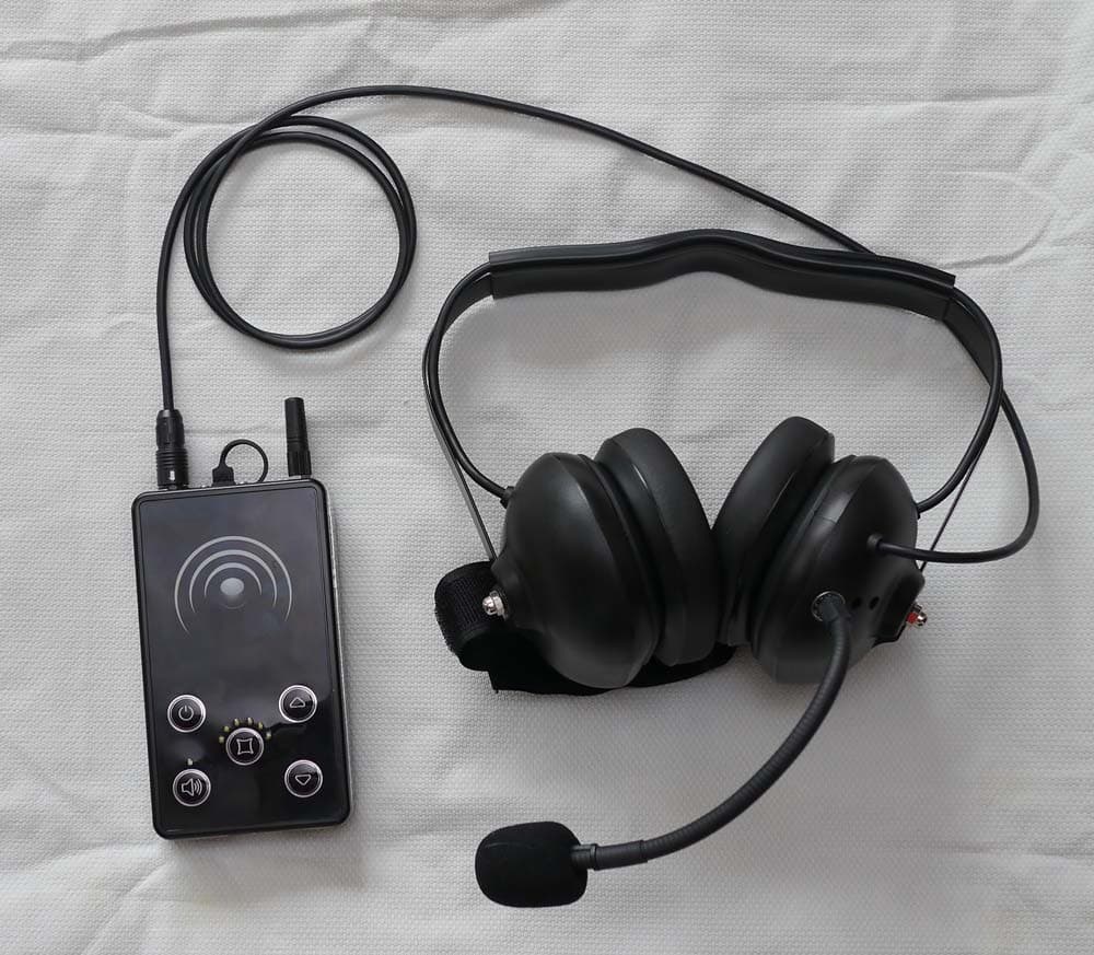
ALZMVR900
May 07, 2012Frequency Hopping Spread Spectrum
Equipment Class
DSS - Part 15 Spread Spectrum Transmitter