ALZMVR900Frequency Hopping Spread Spectrum
Multi-Voice Radio LLC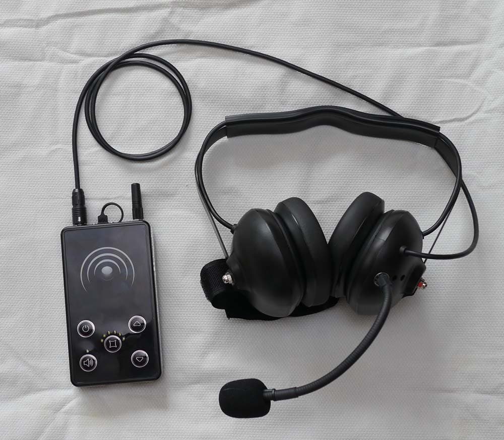
Click to zoom
Application Details
- Equipment Class
- DSS - Part 15 Spread Spectrum Transmitter
- Date of Grant
- May 07, 2012
- Application Purpose
- Original Equipment
- Date of Application
- May 07, 2012
- Equipment Note
- Frequency Hopping Spread Spectrum
- Frequency Range
- 902.80000000 - 926.90000000
- Company
- Multi-Voice Radio LLC
- Country
- United States
Documents & Files
Document Text
Text extracted from the exhibit documents filed with the FCC. Open a document above to read the original.
Users Manual
Rev 1.1 5/3/2012 MVR900 Multi-Voice Radio LLC. 266E 900S Mapleton, UT 84664 (885) 685-8487 • [email protected] www.multivoiceradio.com Compliance to US/CANADA This device complies with part 15 of the FCC rules and with RSS 210 of Industry Canada. Operation is subject to the following two conditions: (1) This device does not cause harmful interference, and (2) this device must accept any interference received, including interference that may cause undesired operation. Note: This equipment has been tested and found to comply with the limits for a Class B digital device, pursuant to Part 15 of the FCC Rules. These limits are designed to provide reasonable protection against harmful interference in a residential installation. This equipment generates, uses and can radiate radio frequency energy and, if not installed and used in accordance with the instructions, may cause harmful interference to radio communications. However, there is no guarantee that interference will not occur in a particular installation. If this equipment does cause harmful interference to radio or television reception, which can be determined by turning the equipment off and on, the user is encouraged to try to correct the interference by one or more of the following measures: • Reorient or relocate the receiving antenna. • Increase the separation between the equipment and receiver. • Connect the equipment into an outlet on a circuit different from that to which the receiver is connected. • Consult the dealer or an experienced radio/TV technician for help. Warning: Changes or modifications made to this equipment not expressly approved by Multi-Voice Radio may void the user’s authority to operate the equipment. This Class B digital device complies with Canadian ICES-003. Cet appareil numérique de la classe B est conforme à la norme NMB-003 du Canada. Le présent appareil est conforme aux CNR d'Industrie Canada applicables aux appareils radio exempts de licence. L'exploitation est autorisée aux deux conditions suivantes : (1) l'appareil ne doit pas produire de brouillage, et (2) l'utilisateur de l'appareil doit accepter tout brouillage radioélectrique subi, même si le brouillage est susceptible d'en compromettre le fonctionnement. FCC ID: ALZMVR900 IC: 10263A-MVR900 Model: MVR900 The Multi-Voice Radio MVR900 System provides advanced full duplex communication. MVR900 Users Guide Rev 1.1 5/3/2012 MVR900 Multi-Voice Radio LLC. 266E 900S Mapleton, UT 84664 (885) 685-8487 • [email protected] www.multivoiceradio.com Product Description The Multi-Voice Radio combines conference communication with wireless radio. This full duplex system allows hands free communication on a secure signal for up to 8 people. Additional units may be added as listen only or push to talk devices. Specifications Required Accessory The MVR900 requires a headset for operation. The headset requirements are: an electret microphone with Impedance between 1KΩ and 5 KΩ, a speaker with impedance between 8 Ω and 50Ω, a hirose HR30-6P-6S71 connector. To see the available headsets visit our website at www.multivoiceradio.com Keypad Description Power ON/OFF Hold the button for 3 seconds to turn the device ON. Hold the button for 3 seconds to turn the device OFF. Volume UP Volume DOWN Mute Press to toggle the microphone off and on. When the device is in the optional PPT mode the button becomes the ppt activation. Channel / Sync Press switch between 6 channels. This button also acts as the sync button during setup. Measurements Length: 5.2 in Height: 3.0 in Width: 1.0 in Antenna: 1.3 In Weight: 10.9 oz Signal Frequency: 902-928 MHz Maximum Output Power: 500mW Range: Up To 3/4 Mile Line of Sight Frequency Hopping Spread Spectrum Proprietary Encryption Battery 14 Hour Operation Rechargeable Lithium-Ion 6000 mAh Mute LED: Indicates the mute is toggled ON Channel LED: Indicates what channel the user is on. Rev 1.1 5/3/2012 MVR900 Multi-Voice Radio LLC. 266E 900S Mapleton, UT 84664 (885) 685-8487 • [email protected] www.multivoiceradio.com Operating Modes Setup Leave all devices off. Choose one device as the master. On this device hold the channel/sync button down. After a few seconds the LEDs will turn on, this indicates the master is in sync mode. Continue to hold the channel/sync button. After the master is in sync mode with the LEDs on, take each additional device within 10 feet of the master and hold the channel/sync button down until the lights start to flash. Release the button. After all additional devices have finished the procedure above. Release the button on the master device. To Enable Push to Talk mode. After the radio is on, press and hold the mute button and the up arrow button at the same time until the LEDs turn off. To return to Full duplex mode, press and hold the mute button and the down arrow button at the same time until the LEDs turn off. Operation To turn on the device press and hold the Power button until a LED turns on. The devices will remember the group it was synchronized too and connect to the group automatically. Adjust volume to a comfortable level. The setup process will need to be redone if the following situations occur: The master is not turned on or missing from the group, a device needs to be removed from the group, a device needs to be added to the group. No part of this document may be reproduced or transmitted (in electronic or paper version, photocopy) without Multi-Voice Radio LLC. consent. This document is subject to change without notice. All trademarks mentioned in this guide are the property of their respective owner. Full Duplex (Primary) Microphone is always on. User can communicate hands free. Each radio with this mode takes 1 of 8 available communication slots. Push To Talk (Optional) User must push a button to activate microphone. This option needs at least one slot to be unused. The number of unused slots determines the number of PTT users that can talk at the same time. Unlimited number of radios …
Text truncated - open the document above for the full version.
Cover Letter(s)
April 11 2012 RE: Signature Authorization for FCC and Industry Canada Certifications To Whom It May Concern: The purpose of this letter is to allow Ron Fraser, of Multi-Voice Radio LLC. the authorization to sign any documents concerning FCC and Industry Canada certifications. Thank you, Dustin Fraser Vice President Multi-Voice Radio LLC. 801-636-9104 www.multivoiceradio.com • [email protected] • 855-685-8487
Cover Letter(s)
April11,2012 Equipment Autorisation Division FederalCommunications Commission 7435 Oakland Mills Road Columbia, MD 21046 FCC ID:_ALZMVR900_ Product Name:_MVR900_ Request for Confidentiality Pursuant to Sections 0.457 and 0.459 of the commissions rules, we hereby request that the following documents be held confidential: • Schematics • Block diagram • Theory of Operation These materials contain trade secrets and proprietary information and are not customarily released to the public. The public disclosure of this information might be harmful to the company and provide unjustified benefits to our competitors. Dated 11th Dayof April 2012 this By:£-· Signature Ron Fraser Printed Title: President On behalf of: Multi•Voice Radio LLC Telephone: (855) 685-8487
External Photos
Front View of the EUT Back View of the EUT Top View of the EUT View of the EUT with Headset Attached
Internal Photos
View of the EUT with Housing Opened View of the EUT Housing Open with Batteries Removed Showing Front Side of the PCB View of the Front Side of the PCB View of the Bottom of the PCB with RF Shield in Place View of the Bottom of the PCB with RF Shield Removed
RF Exposure Info
RF Exposure Evaluation (MPE) Per IC requirements, SARS testing is not required when maximum average power ≤ 60/fGHz mW. For 915MHz, the maximum average power will have to be under 65.57mWatts. The MVR900 has an average power well under the above limit with an on/off time ratio of < 1/8. 8 X 65.57mWatts = 524milliwatts which is greater than 27dBm. All peak power measurements were under the 27dBm limit. Dated this 26 Day of April 20 12 By: Ron Fraser Signature Printed Title: President Telephone: 855 685-8487 www.multivoiceradio.com • [email protected] • 855-685-8487
Test Report
Nemko-CCL, Inc. 1940 West Alexander Street Salt Lake City, UT 84119 801-972-6146 Test Report Certification Test Of: MVR900 FCC ID: ALZMVR900 Test Specification: FCC PART 15, Subpart C Test Report Serial No: 204821-3.1 Applicant: Multi-Voice Radio 266 E 900 S Mapleton, UT 84664 Dates of Test: April 4 and 5, 2012 Issue Date: April 10, 2012 Accredited Testing Laboratory By: NVLAP Lab Code 100272-0 Nemko-CCL, Inc. TEST REPORT: 204821-3.1 FCC ID#: ALZMVR900 Page 2 of 54 CERTIFICATION OF ENGINEERING REPORT This report has been prepared by Nemko-CCL, Inc. to document compliance of the device described below with the requirements of Federal Communications Commission (FCC) Part 15, Subpart C. This report may be reproduced in full. Partial reproduction may only be made with the written consent of the laboratory. The results in this report apply only to the sample tested. - Applicant: Multi-Voice Radio - Manufacturers: Precision Assembly and Newonics, Inc. - Brand Name: Multi-Voice Radio - Model Number: MVR900 - FCC ID Number: ALZMVR900 On this 10 th day of April 2012, I, individually and for Nemko-CCL, Inc., certify that the statements made in this engineering report are true, complete, and correct to the best of my knowledge, and are made in good faith. Although NVLAP has recognized that the Nemko-CCL, Inc. EMC testing facilities are in good standing, this report must not be used to claim product certification, approval, or endorsement by NVLAP, NIST, or any agency of the federal government. Nemko-CCL, Inc. Tested by: Norman P. Hansen EMC Technician Nemko-CCL, Inc. TEST REPORT: 204821-3.1 FCC ID#: ALZMVR900 Page 3 of 54 TABLE OF CONTENTS PAGE SECTION 1.0 CLIENT INFORMATION .................................................................................4 SECTION 2.0 EQUIPMENT UNDER TEST (EUT) ..................................................................5 SECTION 3.0 TEST SPECIFICATION, METHODS & PROCEDURES .............................9 SECTION 4.0 OPERATION OF EUT DURING TESTING ..................................................16 SECTION 5.0 SUMMARY OF TEST RESULTS ...................................................................17 SECTION 6.0 MEASUREMENTS, EXAMINATIONS AND DERIVED RESULTS ..........18 APPENDIX 1 TEST PROCEDURES AND TEST EQUIPMENT ..........................................36 APPENDIX 2 PHOTOGRAPHS ................................................................................................41 APPENDIX 3 MANUFACTURER’S STATEMENT/ATTESTATION .................................54 Nemko-CCL, Inc. TEST REPORT: 204821-3.1 FCC ID#: ALZMVR900 Page 4 of 54 SECTION 1.0 CLIENT INFORMATION 1.1 Applicant: Company Name: Multi-Voice Radio 266 E 900 S Mapleton, UT 84664 Contact Name: Dustin Fraser Title: Vice President 1.2 Manufacturer: Company Name: Precision Assembly 1315 West 400 South Orem, UT 84058 Company Name: Newonics, Inc. 1883 South 5070 Wet Salt Lake City, UT 84104 Nemko-CCL, Inc. TEST REPORT: 204821-3.1 FCC ID#: ALZMVR900 Page 5 of 54 SECTION 2.0 EQUIPMENT UNDER TEST (EUT) 2.1 Identification of EUT: Brand Name: Multi-Voice Radio Model Number: MVR900 Serial Number: Engineering Unit Country of Manufacture: U.S.A. 2.2 Description of EUT: The MVR900 is a wireless communication device operating in the 902 – 928 MHz band that allows for group communications. The MVR900 may be used hands free or may be used as a push to talk device. Ports are provided for connection of a headset and an external power source/battery charger. The MVR900 is powered by 2 SAM i9100 Li-Ion batteries. The MVR900 was tested using 2 different antennas, a Mobil-Advance Industrial Co. Ltd. M020030916 and a 128AM-002 antenna. The MVR900 is a frequency hopping spread spectrum device using 50 channels between 902.8 MHz and 926.9 MHz. See the plots of the channels below. dBm 30 20 10 0 -10 -20 -30 -40 -50 -60 -70 MVR900 Trace A Start: 902.0000 MHzStop: 910.7000 MHz Res BW: 100 kHzVid BW: 300 kHzSweep: 5.00 ms 4/5/2012 10:53:56 AMESU-40CF: 903.267628 MHz Trace Alower channels Mkr Trace X-Axis Value 1 1 Trace A 902.7808 MHz 11.80 dBm 2 2 Trace A 903.2966 MHz 11.86 dBm 3 3 Trace A 903.7288 MHz 11.79 dBm 4 4 Trace A 904.1192 MHz 12.03 dBm 5 5 Trace A 904.6351 MHz 11.97 dBm 6 6 Trace A 905.0813 MHz 12.01 dBm 7 7 Trace A 905.4856 MHz 12.30 dBm 8 8 Trace A 905.9457 MHz 12.27 dBm 9 9 Trace A 906.8101 MHz 12.09 dBm 10 10 Trace A 907.2563 MHz 12.06 dBm 11 11 Trace A 907.6885 MHz 12.06 dBm 12 12 Trace A 908.1346 MHz 11.85 dBm 13 13 Trace A 908.6087 MHz 12.20 dBm 14 14 Trace A 909.0548 MHz 12.31 dBm 15 15 Trace A 909.5428 MHz 12.16 dBm 16 16 Trace A 910.0029 MHz 12.14 dBm 17 17 Trace A 910.4630 MHz 12.13 dBm Nemko-CCL, Inc. TEST REPORT: 204821-3.1 FCC ID#: ALZMVR900 Page 6 of 54 dBm 30 20 10 0 -10 -20 -30 -40 -50 -60 -70 MVR900 Trace A Start: 910.7000 MHzStop: 919.4000 MHz Res BW: 100 kHzVid BW: 300 kHzSweep: 5.00 ms 4/5/2012 10:58:24 AMESU-40CF: 903.267628 MHz Trace Amiddle channels Mkr Trace X-Axis Value 1 1 Trace A 911.2716 MHz 12.02 dBm 2 2 Trace A 911.7736 MHz 12.14 dBm 3 3 Trace A 912.1500 MHz 12.17 dBm 4 4 Trace A 912.6659 MHz 12.22 dBm 5 5 Trace A 913.0981 MHz 12.22 dBm 6 6 Trace A 913.4885 MHz 12.29 dBm 7 7 Trace A 913.9625 MHz 12.39 dBm 8 8 Trace A 914.4226 MHz 12.28 dBm 9 9 Trace A 915.2731 MHz 12.25 dBm 10 10 Trace A 915.7332 MHz 12.36 dBm 11 11 Trace A 916.2212 MHz 12.39 dBm 12 12 Trace A 916.6115 MHz 12.38 dBm 13 13 Trace A 917.1135 MHz 12.49 dBm 14 14 Trace A 917.5596 MHz 12.55 dBm 15 15 Trace A 917.9918 MHz 12.28 dBm 16 16 Trace A 918.4659 MHz 12.42 dBm 17 17 Trace A 918.8423 MHz 12.49 dBm 18 18 Trace A 919.3163 MHz 12.28 dBm dBm 30 20 10 0 -10 -20 -30 -40 -50 -60 -70 MVR900 Trace A Start: 919.4000 MHzStop: 928.0000 MHz Res BW: 100 kHzVid BW: 300 kHzSweep: 5.00 ms 4/5/2012 11:02:26 AMESU-40CF: 903.267628 MHz Trace Aupper channels Mkr Trace X-Axis Value 1 1 Trace A 920.1994 MHz 12.62 dBm 2 2 Trace A 920.6679 MHz 12.51 dBm 3 3 Trace A 921.1228 MHz 12.48 dBm 4 4 Trace A 921.5776 MHz 12.59 dBm 5 5 Trace A 922.018…
Text truncated - open the document above for the full version.
Test Setup Photos
Front View Radiated Disturbance Worst Case Configuration Back View Radiated Disturbance Worst Case Configuration Front View Conducted Disturbance Worst Case Configuration Back View Conducted Disturbance Worst Case Configuration
Contact Information
Applicant
Dustin Fraser
Technical Contact
Multi-Voice RadioDustin Fraser
[email protected]801-636-9149
266 E900 S · Mapleton, Utah · United States
Non-Technical Contact
Multi-Voice RadioRon Fraser
[email protected]801-636-9149
Test Firm
VPI TechnologyJason Stewart
[email protected]801-495-2310
Technical Specifications
| # | Rule Parts | Frequency Range | Power Output |
|---|---|---|---|
| 1 | 15C | 902.8 MHz - 926.9 MHz | 306.20 mW |
Other Applications from Multi-Voice Radio LLC
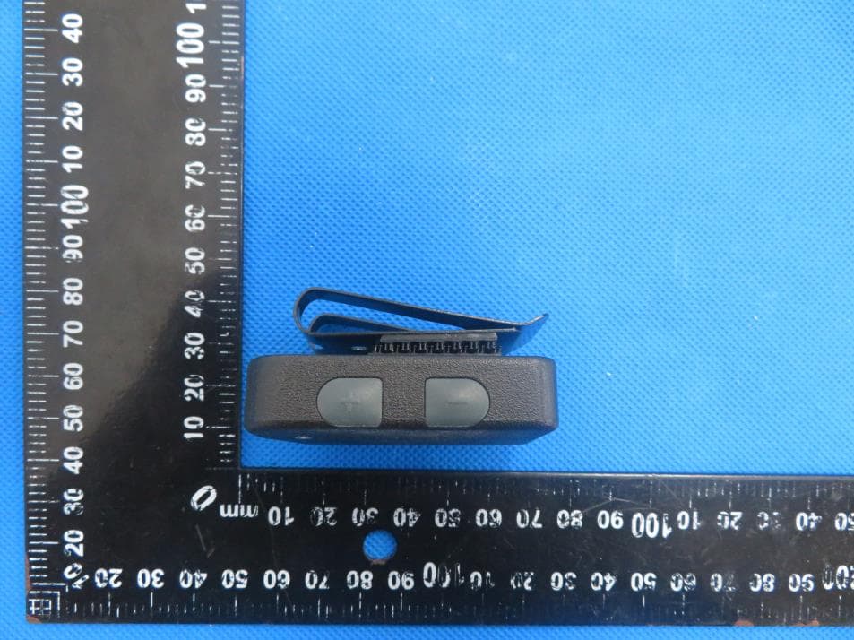
ALZMV2RX
Sep 04, 2023MULTIVOICE Coach to Player receive only device
Equipment Class
DSS - Part 15 Spread Spectrum Transmitter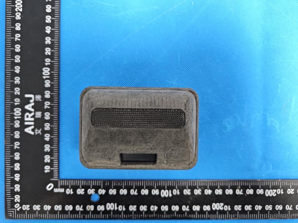
ALZM2P
Aug 30, 2023MV-PAC
Equipment Class
DSS - Part 15 Spread Spectrum Transmitter
ALZMV2
Jun 22, 2020Wireless Communication Headset
Equipment Class
DTS - Digital Transmission System