AMPJ71HColor Monitor
Jean Co Ltd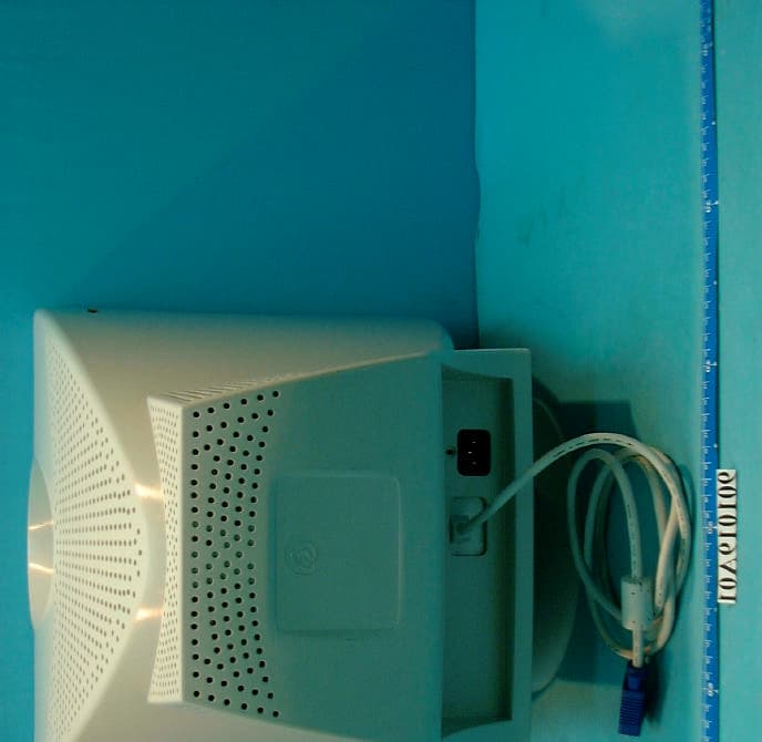
Click to zoom
Application Details
- Equipment Class
- JBP - Part 15 Class B Computing Device Peripheral
- Date of Grant
- Nov 05, 2001
- Application Purpose
- Original Equipment
- Date of Application
- Nov 05, 2001
- Equipment Note
- Color Monitor
- Company
- Jean Co Ltd
- Country
- Taiwan
Documents & Files
Document Text
Text extracted from the exhibit documents filed with the FCC. Open a document above to read the original.
Users Manual
Operation Instructions Thank you for purchasing this monitor, a high-resolution multi-scan color monitor. Please read this guide thoroughly before installation. FCC RADIO FREQUENCY INTERFERENCE STATEMENT WARNING: (FOR FCC CERTIFIED MODELS) This monitor has been tested and found compliant with the limits for a Class B digital device, pursuant to part 15 of the FCC Rules. These limits are designed to provide proper protection against harmful interference to a residential installation. This monitor generates, uses, and can radiate radio frequency energy. Harmful interference to radio communication may be led as a result if it‘s not properly installed and used. However, there is no guarantee that interference will not occur in a particular installation. If this monitor does cause serious interference to radio or television reception, resetting the monitor may determine it. Moreover, users are encouraged to correct interference by doing one or more of the following: ! Reorient or relocate the receiving antenna. ! Move the monitor and the receiver further away from each other. ! Connect the monitor into an outlet on a circuit different from that to which the receiver is connected. ! Consult your local dealer or an qualified technician. FCC Warning: To assure a continued FCC compliance, a user must use a grounded power supply cord and the provided shielded video interface cable with bonded ferrite cores. Also, any unauthorized changes or modifications to this monitor would void the user‘s authority to operate this device. Note: If necessary, shielded interface cables and A.C. power cord must be used to meet the emission level limits. EMI Certification The Class B digital apparatus meets all requirements of the Canadian Interference-Causing Equipment Regulation. Cet appareil numérique de classe B respecte toutes les exigences du Règlement sur le matériel brouilleur du Canada. Content First Step ......................................................................................1 Quick Installation.........................................................................1 Front Panel Control .....................................................................2 Rear Exterior................................................................................2 Feature .........................................................................................3 Using OSD function ....................................................................3 OSD Funtion ................................................................................4 Timing Mode ...............................................................................5 Technical Information .................................................................6 Safety Precautions .......................................................................7 Care and Maintenance .................................................................8 1 First Step Thank you for purchasing this monitor of high performance! This monitor package comes with: # Video cable with 15 pin D-SUB connector. # Power cable. # User guidebook or CD-ROM (You’re reading now) Quick Installation 1. Connect video cable Make sure both the monitor and computer are powered OFF. Connect the video cable to the computer, then to the monitor. 2. Connect power cord Connect the power cord to a properly grounded AC outlet, then to the monitor. 3. Power-ON computer and monitor 4. Windows users :Setting the Timing Mode (Resolution and Refresh Rate) Example: 800 x 600 @ 75 Hz Resolution Right-click on the Windows desktop > Porperties > Settings > “Desktop Area”. Set the resolution. Refresh Rate (vertical frequency) See your graphic card’s user guide for instructions. Power-ON the computer, then Power-ON the monitor. D-Sub Power 2 Front Panel Control ❻ ❺ ❹ ❸ ❷ ❶ ❶ POWER ON/OFF SWITCH ❹ INCREASE BUTTON ❷ POWER ON/OFF INDICATOR ❺ DECREASE BUTTON ❸ FUNCTION ❻ FUNCTION Rear Exterior ❼ ❽ ❼ AC SOCKET ❽ 15 PIN D-TYPE CONNECTOR 1 2 3 Feature This monitor has an adapted advance CPU to control the Contrast, Brightness, Zoom, H-phase, H-size, V-center, V-Size, Pincushion, Trapezoid, Parallelogram, Pin-balance, Rotation, Color temperature, Morie, Language, Degauss. Using OSD function Press function buttons to activate OSD functions and adjust with 3 33 34 44 4 to change function parameter. 2 1 4 OSD Function ICON ITEM DESCRIPTION CONTRAST Increases/decreases video gain. BRIGHTNESS Increases/decreases raster black level. ZOOM Zoom In or Zoom Out the video pattern. HORIZONTAL POSITION Adjusts the H-phase of the picture. HORIZONTAL SIZE Adjusts the H-width of the picture. VERTICAL POSITION Adjusts the vertical placement of the picture . VERTICAL SIZE Adjusts the vertical size of the picture . MEMORY RECALL When use PRESET MODE press - or + to recall the factory default . PINCUSHION Controls the side distortion. TRAPEZIOD Controls the top of the H-width equal to the bottom of the picture . PARALLELOGRAM Controls the vertical line on both sides to become slope and symmetry. PIN-BALANCE Controls the vertical line on both sides to become parabola and symmetry. TILT Controls the tilt of the display image . COLOR Selects color temperature & adjust user color mode. DEGAUSS Degausses the screen. LANGUAGE Multi-language select. Use - and + key to select OSD display language. OSD POSITION Adjust OSD Position. MESSAGE Shows current horizontal & vertical frequency & mode type. 5 Timing Mode Timing modes of 70KHz Industry 640 x 350 @ 70HZ Industry 640 x 480 @ 60HZ VESA 720 x 400 @ 70HZ VESA 640 x 480 @ 75HZ VESA 720 x 400 @ 85HZ VESA 640 x 480 @ 85HZ VESA 800 x 600 @ 72HZ VESA 800 x 600 @ 75HZ VESA 1024 x 768 @ 60HZ VESA 800 x 600 @ 85HZ VESA 1024 x 768 @ 75HZ VESA 1024 x 768 @ 85HZ 6 Technical Information Technical Specification CRT Size Viewable Size Dot Pitch Deflection 17-Inch Flat Type (Flat tube model) 17-Inch Flat Square Type (Traditional Model) 16” Flat 0.25mm / Traditional 0.27mm 90° Input Signal Video Signal Syn…
Text truncated - open the document above for the full version.
External Photos
(Photo 1) FCC IDAMPJ71H (Photo 2) FCC IDAMPJ71H 1
ID Label/Location Info
75 90 R 5.25 This device complies with Part 15 of the FCC Rules. Operation is subject to the following two conditions: (1) this device may not cause harmful interference, and (2) this device must accept any interference received, including interference that may cause undesired operation. Certified to comply with DHHS Rules 21 CFR Subchapter J applicable at the date of manufacture. Complies with Canadian ICES-003 Class B. Conforme a la NMB-003 Class B. Date of Mfg.:Serial No.: MODEL NAME: JD177TF9 Type No.: J71H Rating: 100-240V~ 60/50Hz 2.5A As an ENERGY STAR R Partner, JEAN CO., LTD. has determined that this product meets the ENERGY STAR R guidelines for energy efficiency. FCC ID: AMPJ71H MADE IN TAIWAN JEAN COMPANY LTD. 7F,2, Rei Kuang Road, Nei Hu, Taipei Taiwan E137379 LISTED 6K28 UL1950 R NEUTRAL SET LABEL 20551XXXXX JD177TF9 1:190.10.23mm X 1
ID Label/Location Info
(Fig. 1) FCC ID: AMPJ71H FCC LABEL LOCATION The label will be permanently affixed at a conspicuous location on the device. Label
Internal Photos
(Photo 3) FCC IDAMPJ71H (Photo 4) FCC IDAMPJ71H 1 (Photo 5) FCC IDAMPJ71H 4 (Photo 6) FCC IDAMPJ71H 2 3
Internal Photos
(Photo 7) FCC IDAMPJ71H (Photo 8) FCC IDAMPJ71H (Photo 9) FCC IDAMPJ71H (Photo 10) FCC IDAMPJ71H (Photo 11) FCC IDAMPJ71H 5
Test Report
FCC ID: AMPJ71H Report No.: F901019A011Issued: Oct. 23, 2001 FCC TEST REPORT REPORT NO.: F901019A01 MODEL NO.: JT177XX TYPE NO.: J71H RECEIVED: Oct. 19, 2001 TESTED: Oct. 19, 2001 APPLICANT:JEAN CO., LTD. ADDRESS: 7F, 2, REI KUANG ROAD, NEI HU, TAIPEI, TAIWAN, R.O.C. ISSUED BY:Advance Data Technology Corporation LAB LOCATION:47 14th Lin, Chiapau Tsun, Linko, Taipei, Taiwan, R.O.C. This test report consists of 19 pages in total. It may be duplicated completely for legal use with the approval of the applicant. It should not be reproduced except in full, without the written approval of our laboratory. The client should not use it to claim product endorsement by CNLA, NVLAP or any government agencies. The test results in the report only apply to the tested sample. The test results in this report are traceable to the national or international standards. 0528 Lab Code: 200102-0 FCC ID: AMPJ71H Report No.: F901019A012Issued: Oct. 23, 2001 Table of Contents 1CERTIFICATION............................................................................................. 3 2SUMMARY OF TEST RESULTS..................................................................... 4 3GENERAL INFORMATION ............................................................................. 5 3.1GENERAL DESCRIPTION OF EUT ............................................................... 5 3.2DESCRIPTION OF TEST MODES ................................................................. 5 3.3DESCRIPTION OF SUPPORT UNITS............................................................ 6 4EMISSION TEST ............................................................................................ 7 4.1CONDUCTED EMISSION MEASUREMENT .................................................. 7 4.1.1 LIMITS OF CONDUCTED EMISSION MEASUREMENT ............................... 7 4.1.2 TEST INSTRUMENTS .................................................................................... 7 4.1.3 TEST PROCEDURE ....................................................................................... 8 4.1.4 DEVIATION FROM TEST STANDARD ........................................................... 8 4.1.5 TEST SETUP .................................................................................................. 8 4.1.6 EUT OPERATING CONDITIONS.................................................................... 9 4.1.7 TEST RESULTS............................................................................................ 10 4.2RADIATED EMISSION MEASUREMENT ..................................................... 13 4.2.1 LIMITS OF RADIATED EMISSION MEASUREMENT .................................. 13 4.2.2 TEST INSTRUMENTS .................................................................................. 14 4.2.3 TEST PROCEDURE ..................................................................................... 14 4.2.4 DEVIATION FROM TEST STANDARD ......................................................... 15 4.2.5 TEST SETUP ................................................................................................ 15 4.2.6 EUT OPERATING CONDITIONS.................................................................. 15 4.2.7 TEST RESULTS............................................................................................ 16 5PHOTOGRAPHS OF THE TEST CONFIGURATION ................................... 18 6APPENDIX - INFORMATION ON THE TESTING LABORATORIES............. 20 FCC ID: AMPJ71H Report No.: F901019A013Issued: Oct. 23, 2001 1 CERTIFICATION PRODUCT:Color Monitor BRAND NAME:JEAN MODEL NO:JT177XX TYPE NO:J71H TEST ITEM:ENGINEERING SAMPLE APPLICANT:JEAN CO., LTD. STANDARDS:FCC Part 15, Subpart B, Class B CISPR 22: 1997, Class B ANSI C63.4-1992 We, Advance Data Technology Corporation, hereby certify that one sample (model: JT177TF9 ) of the designation has been tested in our facility on Oct. 19, 2001. The test record, data evaluation and Equipment Under Test (EUT) configurations represented herein are true and accurate accounts of the measurements of the sample's EMC characteristics under the conditions herein specified. FCC ID: AMPJ71H Report No.: F901019A014Issued: Oct. 23, 2001 2 SUMMARY OF TEST RESULTS The EUT has been tested according to the following specifications: StandardTest TypeResultRemarks Conducted TestPASS Meets Class B Limit Minimum passing margin is – 10.07 dB at 21.706 MHz FCC Part 15, Subpart B, Class B / CISPR 22: 1997, Class B Radiated TestPASS Meets Class B Limit Minimum passing margin is –2.8 dB at 195.08 MHz NOTE: For conducted emission test, the test limit used is according to FCC Part 15.107. In this part, conducted emission test for telecom port is not mentioned and therefore this item is not tested. FCC ID: AMPJ71H Report No.: F901019A015Issued: Oct. 23, 2001 3 GENERAL INFORMATION 3.1 GENERAL DESCRIPTION OF EUT PRODUCTCOLOR MONITOR MODEL NO.JT177XX TYPE NO.J71H POWER SUPPLY Switching 100-240V, 2.5A, 50/60Hz Power Cord Non-shielded, AC 3-pin (1.8m) DATA CABLENonshielded (1.5m) with one ferrite core NOTE:The EUT is a 17” COLOR MONITOR with resolution up to 1280 x 1024. The "X" in the model could be defined as A~Z, 0~9 or blank according to different customer’s requirement or marketing differentiation. During the test, the model: JT177TF9 was chosen as a representative model and its data was recorded in this report. For a more detailed features description, please refer to the manufacturer's specifications or the User's Manual. 3.2 DESCRIPTION OF TEST MODES The EUT was pre-tested under the following resolution and horizontal synchronization speed mode: ♦ 1280 x 1024 (60Hz/64kHz) ♦ 1024 x 768 (85Hz/69kHz) ♦ 640 x 480 (60Hz/31.5kHz) The worst emission level was found when the EUT was tested under 1280x1024 (64kHz) resolution, therefore the test data of this mode is recorded in the report. The test mode with worst EMI was chosen for all immunity test items and current harmonic and flicker tests. FCC ID: AMPJ71H Report No.: F901019A016Issued: Oct…
Text truncated - open the document above for the full version.
Test Setup Photos
FCC ID: AMPJ71H Report No.: F901019A0117Issued: Oct. 23, 2001 5 PHOTOGRAPHS OF THE TEST CONFIGURATION CONDUCTED EMISSION TEST FCC ID: AMPJ71H Report No.: F901019A0118Issued: Oct. 23, 2001 RADIATED EMISSION TEST
Contact Information
Applicant
Tony Tsai(Senior Manager of R&D Electrical)
886 2 8792-1188Fax: 886 2 8792-1166
Test Firm
Bureau Veritas CPS (H.K.) Ltd. Taoyuan BranchRichard Chen
Technical Specifications
| # | Rule Parts | Frequency Range | Power Output |
|---|---|---|---|
| 1 | 15B | - | - |
Other Applications from Jean Co Ltd
AMPT51B
Dec 18, 200215" LCD TV Monitor
Equipment Class
JBP - Part 15 Class B Computing Device Peripheral
AMPT81B
Nov 19, 200218" LCD TV Monitor
Equipment Class
JBP - Part 15 Class B Computing Device Peripheral
AMPL81B
Dec 16, 2001LCD Monitor
Equipment Class
JBP - Part 15 Class B Computing Device Peripheral
AMPL71B
Nov 25, 2001LCD Monitor
Equipment Class
JBP - Part 15 Class B Computing Device Peripheral
AMPR90A
Jul 02, 2001Projector
Equipment Class
JBP - Part 15 Class B Computing Device Peripheral