AMPT51B15" LCD TV Monitor
Jean Co Ltd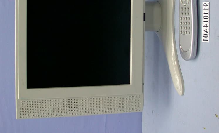
Click to zoom
Application Details
- Equipment Class
- JBP - Part 15 Class B Computing Device Peripheral
- Date of Grant
- Dec 18, 2002
- Application Purpose
- Original Equipment
- Date of Application
- Dec 18, 2002
- Equipment Note
- 15" LCD TV Monitor
- Company
- Jean Co Ltd
- Country
- Taiwan
Documents & Files
Document Text
Text extracted from the exhibit documents filed with the FCC. Open a document above to read the original.
External Photos
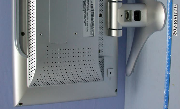
(Photo 1) FCC ID:AMPT51B (Photo 2) FCC ID: AMPT51B
ID Label/Location Info
(Fig. 1) FCC ID: AMPT51B FCC LABEL LOCATION The label will be permanently affixed at a conspicuous location on the device. Label
Internal Photos
(Photo 3) FCC ID: AMPT51B (Photo 4) FCC ID:AMPT51B (Photo 5) FCC ID:AMPT51B (Photo 6) FCC ID: 2 (Photo 7) FCC ID:AMPT51B 1 3 4 5 (Photo 8) FCC ID:AMPT51B (Photo 9) FCC ID:AMPT51B 7 8 9 (Photo 10 ) FCC ID:AMPT51B (Photo 11) FCC ID:AMPT51B 10 (Photo 12 ) FCC ID:AMPT51B (Photo 13 ) FCC ID:AMPT51B (Photo 14 ) FCC ID:AMPT51B 11
Internal Photos
(Photo 14 ) FCC ID:AMPT51B 11 (Photo 15 ) FCC ID:AMPT51B (Photo 16 ) FCC ID:AMPT51B (Photo 17 ) FCC ID:AMPT51B 12 13 (Photo 18 ) FCC ID:AMPT51B (Photo 19 ) FCC ID:AMPT51B (Photo 20 ) FCC ID:AMPT51B 14 (Photo 21 ) FCC ID:AMPT51B 14 15 (Photo 22 ) FCC ID:AMPT51B (Photo 23 ) FCC ID:AMPT51B 16 (Photo 24 ) FCC ID:AMPT51B 16 (Photo 25 ) FCC ID:AMPT51B
Internal Photos
(Photo 26 ) FCC ID:AMPT51B (Photo 27 ) FCC ID:AMPT51B (Photo 28 ) FCC ID:AMPT51B (Photo 29 ) FCC ID:AMPT51B (Photo 30 ) FCC ID:AMPT51B (Photo 31 ) FCC ID:AMPT51B (Photo 32 ) FCC ID:AMPT51B (Photo 33 ) FCC ID:AMPT51B (Photo 34 ) FCC ID:AMPT51B (Photo 35 ) FCC ID:AMPT51B (Photo 36 ) FCC ID:AMPT51B (Photo 37 ) FCC ID:AMPT51B
Internal Photos
(Photo 38 ) FCC ID:AMPT51B (Photo 39 ) FCC ID:AMPT51B (Photo 40 ) FCC ID:AMPT51B 6 (Photo 41 ) FCC ID: AMPT51B (Photo 42 ) FCC ID:AMPT51B (Photo 43 ) FCC ID:AMPT51B (Photo 44 ) FCC ID:AMPT51B (Photo 45 ) FCC ID:AMPT51B (Photo 46 ) FCC ID:AMPT51B (Photo 47 ) FCC ID:AMPT51B (Photo 48 ) FCC ID:AMPT51B
Operational Description
FCC ID: AMPT51B Report No.: F911014A0110Issued: Oct. 22, 2002 4.1.6 EUT OPERATING CONDITIONS a. Turned on the power of all equipment. b. PC ran a test program to enable all functions. c. PC read and wrote messages from FDD and HDD. d. DVD sent video messages (color bar 75/7.5/75/7.5 and 1 kHz audio signal) to EUT. (Mode 2,3) e. PC sent “H” messages to 15” LCD TV MONITOR (EUT) and displayed “H” patterns on its screen. (Mode 1) f. PC sent "H" messages to modem. g. PC sent "H" messages to printer, and the printer printed them on paper. h. PC sent audio messages to EUT’s int. speaker. i. Steps c-i were repeated.
Parts List/Tune Up Info
Federal Communications Commission Date: Nov. 05, 2002 Authorization and Evaluation Division 7435 Oakland Mills Rd. Columbia, MD. 21046 Attention: Authorization and Evaluation Division Subject: RFI related modifications incorporated into unit with - FCC ID: AMPT51B Dear Sirs: This letter serves as our declaration that all modifications listed below were implemented in the sample submitted for testing. We further declare that the same modifications will be implemented into all production units to enhance compliance of the units to FCC limits. The modifications include the following: 1) Added 1 ferrite core from power board to main board with one turn ( see photo 7 ) 2) Added 1 finger & 1 piece of copper foil on the back of cover of EUT ( see photo 6 ) 3) Added 3 pieces of aluminum foil and 1 piece of copper foil on the back cover of main- board ( see photo 7 ) 4) Added 1 piece of aluminum foil and 1 piece copper foil from the cover of main-board to cover of panel ( see photo 7 ) 5) Added 1 ground wire from OSD board to panel case ( see photo 7 ) 6) 3 capacitor on the board of YCbCr port ( see photo 40 ) 7) |Added 2 cores from speaker to main-board with one turn for each (see photo 9) 8) Added 1 piece aluminum foil covered the transformer of tuner (see photo 9) 9) Added 1 gasket on the S-Video port . ( see photo 9 ) 10) Added 3 gasket and 4 fingers on the rear side of main-board ( see photo 11 ) 11) Added 6 gasket on the rear side of panel ( see photo 14 ) 12) Added 2 plane cores on the cable of the panel ( see photo 17 ) 13) Added 2 piece of aluminum foil on the rear side of panel cover (see photo 17) 14) Added 2 piece of copper foil on the tuner box ( see photo 20 & 21 ) 15) Added 2 shielded wire from tuner box connected to main-board ( see photo 21 ) 16) Added 2 gasket on the front and rear side of the tuner board ( see photo 23 & 24 ) If you have any further questions or comments regarding the above, please don't hesitate to contact Ms. Sharon Hsiung of ADT Lab. at fax No.:886-2-2602-2943 or E-mail: [email protected] Sincerely yours, ---------------------------- Sophy Kuo/ Safety Deputy Manager Jean Co., Ltd.
Test Report
FCC ID: AMPT51B Report No.: F911014A011Issued: Oct. 22, 2002 FCC TEST REPORT REPORT NO.:F911014A01 MODEL NO.:JC166H12U TYPE NO.:T51B RECEIVED:Oct. 14, 2002 TESTED:Oct. 17 ~ 18, 2002 APPLICANT: JEAN CO., LTD. ADDRESS: 7F ,2 , Rei Kuang Road, Nei Hu, Taipei, Taiwan, R.O.C ISSUED BY: Advance Data Technology Corporation LAB LOCATION: 47 14th Lin, Chiapau Tsun, Linko, Taipei, Taiwan, R.O.C. This test report consists of 29 pages in total. It may be duplicated completely for legal use with the approval of the applicant. It should not be reproduced except in full, without the written approval of our laboratory. The client should not use it to claim product endorsement by CNLA, NVLAP or any government agencies. The test results in the report only apply to the tested sample. The test results in the report only apply to the tested sample. 0528 ILAC MRA Lab Code: 200102-0 FCC ID: AMPT51B Report No.: F911014A012Issued: Oct. 22, 2002 Table of Contents 1CERTIFICATION............................................................................................. 3 2SUMMARY OF TEST RESULTS .................................................................... 4 3GENERAL INFORMATION ............................................................................. 5 3.1GENERAL DESCRIPTION OF EUT ................................................................5 3.2DESCRIPTION OF TEST MODES ..................................................................5 3.3DESCRIPTION OF SUPPORT UNITS ............................................................7 4EMISSION TEST ............................................................................................ 8 4.1CONDUCTED EMISSION MEASUREMENT...................................................8 4.1.1 LIMITS OF CONDUCTED EMISSION MEASUREMENT ................................8 4.1.2 TEST INSTRUMENTS.....................................................................................8 4.1.3 TEST PROCEDURE........................................................................................9 4.1.4 DEVIATION FROM TEST STANDARD............................................................9 4.1.5 TEST SETUP...................................................................................................9 4.1.6 EUT OPERATING CONDITIONS ..................................................................10 4.1.7 TEST RESULTS (A)....................................................................................... 11 4.1.8 TEST RESULTS (B).......................................................................................13 4.1.9 TEST RESULTS (C) ......................................................................................15 4.2RADIATED EMISSION MEASUREMENT......................................................17 4.2.1 LIMITS OF RADIATED EMISSION MEASUREMENT ...................................17 4.2.2 TEST INSTRUMENTS...................................................................................17 4.2.3 TEST PROCEDURE......................................................................................18 4.2.4 DEVIATION FROM TEST STANDARD..........................................................18 4.2.5 TEST SETUP.................................................................................................18 4.2.6 EUT OPERATING CONDITIONS ..................................................................18 4.2.7 TEST RESULTS (A).......................................................................................19 4.2.8 TEST RESULTS (B).......................................................................................21 4.2.9 TEST RESULTS (C) ......................................................................................23 5PHOTOGRAPHS OF THE TEST CONFIGURATION ................................... 25 6APPENDIX - INFORMATION ON THE TESTING LABORATORIES ............ 29 FCC ID: AMPT51B Report No.: F911014A013Issued: Oct. 22, 2002 1 CERTIFICATION PRODUCT:15” LCD TV MONITOR BRAND NAME:JEAN MODEL NO.:JC166H12U TYPE NO.:T51B TEST ITEM:ENGINEERING SAMPLE APPLICANT:JEAN CO., LTD. STANDARDS:FCC Part 15, Subpart B, Class B CISPR 22: 1997, Class B ANSI C63.4-1992 We, Advance Data Technology Corporation, hereby certify that one sample of the designation has been tested in our facility on Oct. 17 ~ 18, 2002. The test record, data evaluation and Equipment Under Test (EUT) configurations represented herein are true and accurate accounts of the measurements of the sample's EMC characteristics under the conditions herein specified. CHECKED BY: , DATE: Oct. 22, 2002 APPROVED BY: ( Kathy Tseng ) , DATE: Oct. 22, 2002 (Fred Chen, Manager ) FCC ID: AMPT51B Report No.: F911014A014Issued: Oct. 22, 2002 2 SUMMARY OF TEST RESULTS The EUT has been tested according to the following specifications: StandardTest TypeResultRemarks Conducted TestPASS Meets Class B Limit Minimum passing margin is –3.84 dB at 0.150 MHz FCC Part 15, Subpart B, Class B CISPR 22: 1997, Class B ANSI C63.4-1992 Radiated TestPASS Meets Class B Limit Minimum passing margin is –3.00 dB at 715.99 MHz FCC ID: AMPT51B Report No.: F911014A015Issued: Oct. 22, 2002 3 GENERAL INFORMATION 3.1 GENERAL DESCRIPTION OF EUT PRODUCT15” LCD TV MONITOR MODEL NO.JC166H12U TYPE NO.T51B POWER SUPPLY Switching 100-240, 1.2A, 50-60Hz Power cord Non-shielded AC (1.8m, 3-pin) DATA CABLE VGA Cable shielded (1.5m) with 2 ferrite cores NOTE: The EUT is a 15” LCD TV MONITOR attached with a remove controller, with resolution up to 1024x768. It has monitor as well as TV function. This report covers monitor function only. Its TV function test data is covered in another test report no.: F911014A01A. For a more detailed features description, please refer to the manufacturer's specifications or the User's Manual. 3.2 DESCRIPTION OF TEST MODES The EUT was pre-tested under the following resolution and horizontal synchronization speed mode: z 1024 x 768 (75Hz/60kHz) z 800 x 600 (75Hz/47kHz) z 640 x 480 (60Hz/31.5kHz) The worst emission level wa…
Text truncated - open the document above for the full version.
Test Setup Photos
FCC ID: AMPT51B Report No.: F911014A0126Issued: Oct. 22, 2002 5 PHOTOGRAPHS OF THE TEST CONFIGURATION CONDUCTED EMISSION TEST (for Mode 1) FCC ID: AMPT51B Report No.: F911014A0127Issued: Oct. 22, 2002 CONDUCTED EMISSION TEST (for Mode 2, 3) FCC ID: AMPT51B Report No.: F911014A0128Issued: Oct. 22, 2002 RADIATED EMISSION TEST (for Mode 1) FCC ID: AMPT51B Report No.: F911014A0129Issued: Oct. 22, 2002 RADIATED EMISSION TEST (for Mode 2, 3)
Contact Information
Applicant
Tony Tsai(Senior Manager of R&D Electrical)
886 2 8792-1188Fax: 886 2 8792-1166
Test Firm
Bureau Veritas CPS (H.K.) Ltd. Taoyuan BranchTommy Wu
Technical Specifications
| # | Rule Parts | Frequency Range | Power Output |
|---|---|---|---|
| 1 | 15B | - | - |
Other Applications from Jean Co Ltd
AMPT81B
Nov 19, 200218" LCD TV Monitor
Equipment Class
JBP - Part 15 Class B Computing Device Peripheral
AMPL81B
Dec 16, 2001LCD Monitor
Equipment Class
JBP - Part 15 Class B Computing Device Peripheral
AMPL71B
Nov 25, 2001LCD Monitor
Equipment Class
JBP - Part 15 Class B Computing Device Peripheral
AMPJ71H
Nov 05, 2001Color Monitor
Equipment Class
JBP - Part 15 Class B Computing Device Peripheral
AMPR90A
Jul 02, 2001Projector
Equipment Class
JBP - Part 15 Class B Computing Device Peripheral