ARA-COMPACT2XBase Station Transceiver
Telrad Networks Ltd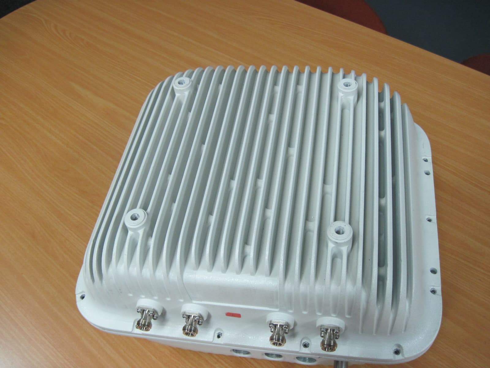
Click to zoom
Application Details
- Equipment Class
- TNB - Licensed Non-Broadcast Station Transmitter
- Date of Grant
- Jul 20, 2014
- Application Purpose
- Original Equipment
- Date of Application
- Jul 20, 2014
- Equipment Note
- Base Station Transceiver
- Frequency Range
- 2501.00000000 - 2685.00000000
- Company
- Telrad Networks Ltd
- Country
- Israel
Documents & Files
Document Text
Text extracted from the exhibit documents filed with the FCC. Open a document above to read the original.
Users Manual
System Manual BreezeCOMPACT - Release 5.0 Release Version:5.0 May 2014 i Legal Rights BreezeCOMPACT System Manual Legal Rights © Copyright 2014 Telrad Networks Ltd. All rights reserved. The material contained herein is proprietary, privileged, and confidential and owned by Telrad Networks or its third party licensors. No disclosure thereof shall be made to third parties without the express written permission of Telrad Networks Ltd. Telrad Networks Ltd. reserves the right to alter the equipment specifications and descriptions in this publication without prior notice. No part of this publication shall be deemed to be part of any contract or warranty unless specifically incorporated by reference into such contract or warranty. Trade Names BreezeCOM ® , WALKair ® , WALKnet ® , BreezeMAX ® , BreezeLITE ® , BreezePHONE ® , 4Motion ® , and/or other products andTelrad Networks/or services referenced here in are either registered trademarks, trademarks or service marks of Telrad Networks Ltd. All other names are or may be the trademarks of their respective owners. “WiMAX Forum” is a registered trademark of the WiMAX Forum. “WiMAX,” the WiMAX Forum logo, “WiMAX Forum Certified”, and the WiMAX Forum Certified logo are trademarks of the WiMAX Forum. Statement of Conditions The information contained in this manual is subject to change without notice. Telrad Networks Ltd. shall not be liable for errors contained herein or for incidental or consequential damages in connection with the furnishing, performance, or use of this manual or equipment supplied with it. Warranties and Disclaimers All Telrad Networks Ltd. (“Telrad Networks“) products purchased from Telrad Networks or through any of Telrad Networks's authorized resellers are subject to the following warranty and product liability terms and conditions. Exclusive Warranty (a) Telrad Networks warrants that the Product hardware it supplies and the tangible media on which any software is installed, under normal use and conditions, will be free from significant defects in materials and workmanship for a period of fourteen (14) months from the date of shipment of a given Product to Purchaser (the "Warranty Period"). Telrad Networks will, at its sole option and as Purchaser's sole remedy, repair or replace any defective Product in accordance with Telrad Networks' standard R&R procedure. (b) With respect to the Firmware, Telrad Networks warrants the correct functionality according to the attached documentation, for a period of fourteen (14) month from invoice date (the "Warranty Period")". During the Warranty Period, Telrad Networks may release to its Customers firmware updates, which include additional performance improvements and/or bug fixes, upon availability (the "Warranty"). Bug fixes, temporary patches and/or workarounds may be supplied as Firmware updates. Additional hardware, if required, to install or use Firmware updates must be purchased by the Customer. Telrad will be obligated to support solely the two (2) most recent Software major releases. TELRAD NETWORKS SHALL NOT BE LIABLE UNDER THIS WARRANTY IF ITS TESTING AND EXAMINATION DISCLOSE THAT THE ALLEGED DEFECT IN THE PRODUCT DOES NOT EXIST OR WAS CAUSED BY PURCHASER'S OR ANY THIRD PERSON'S MISUSE, NEGLIGENCE, IMPROPER INSTALLATION OR IMPROPER TESTING, UNAUTHORIZED ATTEMPTS TO REPAIR, OR ANY OTHER CAUSE BEYOND THE RANGE OF THE INTENDED USE, OR BY ACCIDENT, FIRE, LIGHTNING OR OTHER HAZARD. ii Legal Rights BreezeCOMPACT System Manual Disclaimer (a) The Software is sold on an "AS IS" basis. Telrad Networks, its affiliates or its licensors MAKE NO WARRANTIES, WHATSOEVER, WHETHER EXPRESS OR IMPLIED, WITH RESPECT TO THE SOFTWARE AND THE ACCOMPANYING DOCUMENTATION. TELRAD NETWORKS SPECIFICALLY DISCLAIMS ALL IMPLIED WARRANTIES OF MERCHANTABILITY AND FITNESS FOR A PARTICULAR PURPOSE AND NON-INFRINGEMENT WITH RESPECT TO THE SOFTWARE. UNITS OF PRODUCT (INCLUDING ALL THE SOFTWARE) DELIVERED TO PURCHASER HEREUNDER ARE NOT FAULT-TOLERANT AND ARE NOT DESIGNED, MANUFACTURED OR INTENDED FOR USE OR RESALE IN APPLICATIONS WHERE THE FAILURE, MALFUNCTION OR INACCURACY OF PRODUCTS CARRIES A RISK OF DEATH OR BODILY INJURY OR SEVERE PHYSICAL OR ENVIRONMENTAL DAMAGE ("HIGH RISK ACTIVITIES"). HIGH RISK ACTIVITIES MAY INCLUDE, BUT ARE NOT LIMITED TO, USE AS PART OF ON-LINE CONTROL SYSTEMS IN HAZARDOUS ENVIRONMENTS REQUIRING FAIL-SAFE PERFORMANCE, SUCH AS IN THE OPERATION OF NUCLEAR FACILITIES, AIRCRAFT NAVIGATION OR COMMUNICATION SYSTEMS, AIR TRAFFIC CONTROL, LIFE SUPPORT MACHINES, WEAPONS SYSTEMS OR OTHER APPLICATIONS REPRESENTING A SIMILAR DEGREE OF POTENTIAL HAZARD. TELRAD NETWORKS SPECIFICALLY DISCLAIMS ANY EXPRESS OR IMPLIED WARRANTY OF FITNESS FOR HIGH RISK ACTIVITIES. (b) PURCHASER'S SOLE REMEDY FOR BREACH OF THE EXPRESS WARRANTIES ABOVE SHALL BE REPLACEMENT OR REFUND OF THE PURCHASE PRICE AS SPECIFIED ABOVE, AT TELRAD NETWORKS'S OPTION. TO THE FULLEST EXTENT ALLOWED BY LAW, THE WARRANTIES AND REMEDIES SET FORTH IN THIS AGREEMENT ARE EXCLUSIVE AND IN LIEU OF ALL OTHER WARRANTIES OR CONDITIONS, EXPRESS OR IMPLIED, EITHER IN FACT OR BY OPERATION OF LAW, STATUTORY OR OTHERWISE, INCLUDING BUT NOT LIMITED TO WARRANTIES, TERMS OR CONDITIONS OF MERCHANTABILITY, FITNESS FOR A PARTICULAR PURPOSE, SATISFACTORY QUALITY, CORRESPONDENCE WITH DESCRIPTION, NON-INFRINGEMENT, AND ACCURACY OF INFORMATION GENERATED. ALL OF WHICH ARE EXPRESSLY DISCLAIMED. TELRAD NETWORKS' WARRANTIES HEREIN RUN ONLY TO PURCHASER, AND ARE NOT EXTENDED TO ANY THIRD PARTIES. TELRAD NETWORKS NEITHER ASSUMES NOR AUTHORIZES ANY OTHER PERSON TO ASSUME FOR IT ANY OTHER LIABILITY IN CONNECTION WITH THE SALE, INSTALLATION, MAINTENANCE OR USE OF ITS PRODUCTS. Limitation of Liability (a) TELRAD NETWORKS SHALL NOT BE LIABLE TO THE PURCHASER OR TO ANY THIRD PARTY, FOR ANY LOSS OF PROFITS, LOSS OF USE, INTERRUPTION OF BUSINESS OR FOR ANY INDIRECT, SPECIAL, INCIDENTAL, PUNITIVE OR CONSEQUENTIAL DAMAGES OF ANY KIND, WHETHER ARISING UNDER BREACH OF CONTRACT, TORT (IN…
Text truncated - open the document above for the full version.
Operational Description
Breeze Compact 2.5G Base station is a high capacity, IP services oriented Broadband Wireless Access system. Breeze Compact 2.5G is digital modulated TDD system covering 2496 MHz up to 2690 range. The system contains an all outdoor base station unit. The basic base station system configuration is contains power supply, MODEM and based on RF IC radio. The following describes the transmit path and receive path of the Breeze Compact 2.5G. Note: The ODU consists of four identical RF radio paths based on two identical RF IC chipsets, all paths terminated with antenna ports. Only two radio paths that based on one RF IC are described in the detailed block diagram. The DC voltage applied to the final RF amplifying device is 28VDC. Transmit mode: The signal flow in transmit mode is as follows: The IQ signal passes from the Modem to radio part, and converted to required RF frequency by RF IC then the signal passes thru combo Balun+BPF, GVA-63+ and MGA635P8 amplifiers, amplified again by MGA-22033, then passes thru cable to high power card and amplified again by BLF6G27-10G and BLF7G27L-90P. The amplified signal passes thru circulator and cavity filter (2496- 2690MHz) directly to antenna port. Receive mode: The signal flow in the receive mode is as follows: The unit antenna receives the signal. The received signal passes thru cavity filter (2496-2690MHz), circulator and TX/RX switch. The LNA MGA635P8, combo Balun+BPF directly to the RF IC, converted to IQ signal and directed to the Modem.
Parts List/Tune Up Info
Breeze COMPACT June 25, 2014 CMP3000-B41-2496-2690MHz FCC ID: ARA-COMPACT2X Frequency and power determination before shipment: Before the product shipment from the factory, the units pass automatic calibration sequence tests where the unit is calibrated (including power out) and frequency is tested. Base station installation. The user configures the unit according to licensed frequencies (user may have several frequencies) Power Tune-up Procedure The output power of the unit is controlled by software. There is no hardware adjustment for power setting. When the system operator need to change the power setting at the Base Station , change can be made through the software commands from the remote Operation & Control center or from the local PC. Tolerance rated power: ±1dB The output power level at the highest and the lowest channel frequency is Automatically limited by the software in order to meet the spurious r equirement at the band edge frequencies.
RF Exposure Info
2 1 cm mW R.F Exposure/Safety Calculation for CMP3000-B41-2496-2690 MHz The E.U.T. is pole mounted. Calculation of Maximum Permissible Exposure (MPE) Based on Section 1.1307(b)(1) Requirements (a) FCC limit at 2496-2690 MHz is: Using table 1 of Section 1.1310 limit for general population/uncontrolled exposures, the above level is an average over 30 minutes. (b) The power density produced by the E.U.T. is P t - Transmitted Peak Power (worst case) G T - Antenna Gain, dBi R- Distance from Transmitter S- MPE =1 2 4R GP S tt π = π4 tt GP R= (c) The calculated minimum distance between the EUT antenna and the general public is: Operation Frequency Modulation MIMO Pt MIMO Pt Antenna Type G T G T R (MHz) (dBm) (mW) (dBi) numeric (cm) 2498.50 QPSK 44.73 29717 External 18.0 63.1 386.3 16QAM 44.77 29992 External 18.0 63.1 388.1 64QAM 44.68 29377 External 18.0 63.1 384.1 2593.00 QPSK 44.43 27733 External 18.0 63.1 373.2 16QAM 44.50 28184 External 18.0 63.1 376.2 64QAM 44.41 27606 External 18.0 63.1 372.3 2687.50 QPSK 44.56 28576 External 18.0 63.1 378.8 16QAM 44.67 29309 External 18.0 63.1 383.6 64QAM 44.58 28708 External 18.0 63.1 379.7 5MHz Bandwidth, MIMO Operation Operation Frequency Modulation MIMO Pt MIMO Pt Antenna Type G T G T R (MHz) (dBm) (mW) (dBi) numeric (cm) 2501.00 QPSK 44.62 28973 External 18.0 63.1 381.4 16QAM 44.73 29717 External 18.0 63.1 386.3 64QAM 44.47 27990 External 18.0 63.1 374.9 2593.00 QPSK 44.54 28445 External 18.0 63.1 377.9 16QAM 44.71 29580 External 18.0 63.1 385.4 64QAM 44.39 27479 External 18.0 63.1 371.5 2685.00 QPSK 44.38 27416 External 18.0 63.1 371.0 16QAM 44.50 28184 External 18.0 63.1 376.2 64QAM 44.25 26607 External 18.0 63.1 365.5 10MHz Bandwidth, MIMO Operation
Test Report
Test Report E137671.00 Telrad Networks Ltd. Page 1 of 163 FCC ACC M Ver 1.1 05Mayl 2000 DATE: 10 July 2014 I.T.L. (PRODUCT TESTING) LTD. FCC Radio Test Report for Telrad Networks Ltd. Equipment under test: BreezeCompact 3000 Base Station CMP3000-B41-2496-2690MHz Written by: _____________________________ D. Shidlowsky, Documentation Approved by: _____________________________ A. Sharabi, Test Engineer Approved by: For/ _________________________ I. Raz, EMC Laboratory Manager This report must not be reproduced, except in full, without the written permission of I.T.L. (Product Testing) Ltd. This report relates only to items tested. Test Report E137671.00 Telrad Networks Ltd. Page 2 of 163 FCC ACC M Ver 1.1 05Mayl 2000 Measurement/Technical Report for Telrad Networks Ltd. BreezeCompact 3000 Base Station CMP3000-B41-2496-2690MHz FCC ID: ARA-COMPACT2X This report concerns: Original Grant: X Class II change: Class I change: Equipment type: Licensed Non-Broadcast Transmitter Limits used: 47CFR Part 27 Measurement procedure used is ANSI C63.4-2003. Substitution Method used as in ANSI/TIA-603-C: 2004 Application for Certification Applicant for this device: prepared by: (different from "prepared by") David Shidlowsky Klara Milman ITL (Product Testing) Ltd. Telrad Networks Ltd. Kfar Bin Nun 1 Batsheva St., P.O.B 6118 D.N. Shimshon 9978000 Lod 711600 Israel Israel e-mail [email protected] Tel: +972-73-246-7651 Fax: +972-73-246-7504 e-mail: [email protected] Test Report E137671.00 Telrad Networks Ltd. Page 3 of 163 FCC ACC M Ver 1.1 05Mayl 2000 TABLE OF CONTENTS 1. GENERAL INFORMATION ------------------------------------------------------------------------------- 5 1.1 Administrative Information ................................................................................. 5 1.2 List of Accreditations ......................................................................................... 6 1.3 Product Description ........................................................................................... 7 1.4 Test Methodology .............................................................................................. 7 1.5 Test Facility ....................................................................................................... 7 1.6 Measurement Uncertainty ................................................................................. 8 2. SYSTEM TEST CONFIGURATION --------------------------------------------------------------------- 9 2.1 Justification ........................................................................................................ 9 2.2 EUT Exercise Software ..................................................................................... 9 2.3 Special Accessories .......................................................................................... 9 2.4 Equipment Modifications ................................................................................... 9 2.5 Configuration of Tested System ...................................................................... 10 3. TEST SET-UP PHOTOS ---------------------------------------------------------------------------------- 11 4. MAXIMUM PEAK OUTPUT POWER 5 MHZ BANDWIDTH ------------------------------------- 14 4.1 Test Specification ............................................................................................ 14 4.2 Test procedure ................................................................................................ 14 4.1 Test Results..................................................................................................... 15 4.2 Test Equipment Used ...................................................................................... 35 5. MAXIMUM PEAK OUTPUT POWER 10 MHZ BANDWIDTH ----------------------------------- 36 5.1 Test Specification ............................................................................................ 36 5.2 Test procedure ................................................................................................ 36 5.3 Test Results..................................................................................................... 37 5.4 Test Equipment Used. ..................................................................................... 56 6. SPECTRAL POWER DENSITY 5 MHZ BANDWIDTH -------------------------------------------- 57 6.1 Test Specification ............................................................................................ 57 6.2 Test procedure ................................................................................................ 57 6.3 Test Results..................................................................................................... 57 6.4 Test Equipment Used. ..................................................................................... 78 7. SPECTRAL POWER DENSITY 10 MHZ BANDWIDTH ------------------------------------------ 79 7.1 Test Specification ............................................................................................ 79 7.2 Test procedure ................................................................................................ 79 7.3 Test Results..................................................................................................... 79 7.1 Test Equipment Used. ................................................................................... 100 8. OCCUPIED BANDWIDTH 5 MHZ BANDWIDTH ------------------------------------------------- 101 8.1 Test Specification .......................................................................................... 101 8.2 Test Procedure .............................................................................................. 101 8.3 Test Results................................................................................................... 101 8.4 Test Equipment Used. ................................................................................... 106 9. OCCUPIED BANDWIDTH 1…
Text truncated - open the document above for the full version.
Contact Information
Applicant
Yishai Amsterdamer(VP R&D)
Test Firm
Israel Testing LaboratoriesIIan Cohen
Technical Specifications
| # | Rule Parts | Frequency Range | Power Output | Emission | Tolerance |
|---|---|---|---|---|---|
| 2 | 27 | 2.50 GHz - 2.69 GHz | 29.717 W | 10M0W7D | 400 Hz |
Other Applications from Telrad Networks Ltd

ARA-CPE12350
Feb 08, 2021CPE12350
Equipment Class
CBD - Citizens Band Category A and B Devices
ARA-CPE12000PRO3X
Jun 02, 2020LTE Outdoor CPE12000
Equipment Class
CBD - Citizens Band Category A and B Devices
ARA-CPE8KPRO3XA
May 20, 2020LTE Outdoor CBRS and CPE
Equipment Class
CBD - Citizens Band Category A and B Devices
ARA-2D1VWIFIAP
Jun 29, 2015DM-CPE7000-Indoor-2D-1V-WiFi-AP
Equipment Class
DTS - Digital Transmission System
ARA-COMPACT23X
Jun 24, 2015BreezeCompact 3000 Base Station
Equipment Class
TNB - Licensed Non-Broadcast Station Transmitter