AU792U04A22740Dual Band CDMA Wireless Modem
Multi Tech Systems Inc
Click to zoom
Application Details
- Equipment Class
- PCB - PCS Licensed Transmitter
- Date of Grant
- Feb 10, 2004
- Application Purpose
- Original Equipment
- Date of Application
- Feb 10, 2004
- Equipment Note
- Dual Band CDMA Wireless Modem
- Frequency Range
- 824.70000000 - 848.31000000
- Company
- Multi Tech Systems Inc
- Country
- United States
Documents & Files
Document Text
Text extracted from the exhibit documents filed with the FCC. Open a document above to read the original.
Users Manual
SocketModem ™ CDMA Embedded Data/Fax Wireless Modem MTSMMC-C – Global CDMA 2000 1xRTT, 800/1900 MHz Developer’s Guide Global SocketModem CDMA Developer’s Guide MTSMMC-C – CDMA 2000 1xRTT, 800/1900 MHz PN S000298A, Version A Copyright This publication may not be reproduced, in whole or in part, without prior expressed written permission from Multi-Tech Systems, Inc. All rights reserved. Copyright © 2003, by Multi-Tech Systems, Inc. Multi-Tech Systems, Inc. makes no representations or a warranty with respect to the contents hereof and specifically disclaims any implied warranties of merchantability or fitness for any particular purpose. Furthermore, Multi-Tech Systems, Inc. reserves the right to revise this publication and to make changes from time to time in the content hereof without obligation of Multi-Tech Systems, Inc. to notify any person or organization of such revisions or changes. Revisions Revision LevelDate Description A06/09/03Initial release. Patents This device covered by the following patent: 5,673,268 Trademarks Multi-Tech Trademarks: SocketModem, Multi-Tech, and the Multi-Tech logo. All other products and technologies are the trademarks or registered trademarks of their respective holders. World Headquarters Multi-Tech Systems, Inc. 2205 Woodale Drive Mounds View, Minnesota 55112 Phone: 763-785-3500 or 800-328-9717 Fax: 763-785-9874 Technical Support CountryBy EmailBy Phone France:[email protected](33) 1-64 61 09 81 India: [email protected] (124) 6340778 U.K.:[email protected](44) 118 959 7774 U.S. and Canada: [email protected](800) 972-2439 Rest of the World: [email protected](763) 717-5863 Internet Address: http://www.multitech.com Table of Contents Multi-Tech Systems, Inc. SocketModem CDMA Developer’s Guide3 Table of Contents CHAPTER 1 – PRODUCT DESCRIPTION AND SPECIFICATIONS .......................................................... 4 P RODUCT DESCRIPTION...............................................................................................................................4 A PPLICATIONS.............................................................................................................................................. 4 P RODUCT FEATURES.................................................................................................................................... 5 F EATURE DETAILS........................................................................................................................................ 5 D EVELOPER’S KIT........................................................................................................................................ 5 T ECHNICAL SPECIFICATIONS......................................................................................................................... 6 R ELATED MANUALS...................................................................................................................................... 6 A DDITIONAL INFORMATION............................................................................................................................ 6 CHAPTER 2 – MECHANICAL SPECIFICATIONS ...................................................................................... 7 P HYSICAL DIMENSIONS................................................................................................................................. 7 P IN CONFIGURATIONS.................................................................................................................................. 8 Pin Descriptions...................................................................................................................................... 8 CHAPTER 3 – ELECTRICAL CHARACTERISTICS ................................................................................... 9 I/O E LECTRICAL CHARACTERISTICS.............................................................................................................. 9 P OWER CONSUMPTION................................................................................................................................. 9 H ANDLING PRECAUTIONS............................................................................................................................. 9 CHAPTER 4 – SOCKETMODEM INTERFACES....................................................................................... 10 F LASHING LED .......................................................................................................................................... 10 RF I NTERFACE........................................................................................................................................... 10 RF Connector ....................................................................................................................................... 10 T RANSMITTER SPECIFICATIONS................................................................................................................... 10 R ECEIVER SPECIFICATIONS........................................................................................................................ 11 CHAPTER 5 – SOCKETMODEM TEST BOARD ...................................................................................... 12 S ERIAL TEST/DEMO BOARD COMPONENTS.................................................................................................. 12 S ERIAL TEST/DEMO BOARD BLOCK DIAGRAM.............................................................................................. 13 CHAPTER 6 – APPLICATION CONSIDERATIONS.................................................................................. 14 G ENERAL GUIDELINES FOR THE USE OF THE SOCKETMODEM....................................................................... 14 Hardware and RF ................................................................................................................................. 14 The Antenna ......................…
Text truncated - open the document above for the full version.
External Photos
MTSMC-C FCC ID: AU792U04A22740 External photos MTSMC-C – Top view MTSMC-C FCC ID: AU792U04A22740 External photos MTSMC-C – Bottom view MTSMC-C FCC ID: AU792U04A22740 External photos MTSMC-C in test fixture – Top view MTSMC-C FCC ID: AU792U04A22740 External photos MTSMC-C in test fixture – Bottom view
ID Label/Location Info
Label location
Internal Photos
MTSMC-C FCC ID: AU792U04A22740 Internal photos MTSMC-C – PCB Top view MTSMC-C FCC ID: AU792U04A22740 Internal photos MTSMC-C – PCB Bottom view WAVECOM FCC ID: O9EQ2438 EUT Photographs © 2003 PCTEST Lab. Dual-Band Wireless Module Model: Q2438
RF Exposure Info
INSTALLATION AND INSTRUCTION MANUAL INCLUDING HUMAN EXPOSURE STATEMENT As required by § 2.1033(c)(3), here is a part of the User's Guide and Technical Manual"that describes modem features, installation, and operation. Also provided, in User’s Manual, is a statement addressing human exposure to radio frequency radiation. This information is necessary to ensure that equipment installers, operators and users are made aware of the dangers of exposure to radio frequency radiation and that the Modem is installed and operated in compliance with 47 CFR Part 24, Subpart E and 47 CFR Part 22, Subpart H of the FCC Rules and Regulations. Pursuant to § 24.52 RF hazards, all emissions from the Modem, both fundamental and unwanted, are subject to the radio frequency radiation exposure requirements given in § 1.1307(b), § 2.1091 and § 2.1093, as appropriate. For fixed transmitters, § 1.1307(b) requires the preparation of an Environmental Assessment (EA) if the transmitter would cause human exposure to levels of radio frequency radiation in excess of the applicable limits given in § 1.1310. However, determination of compliance with these limits and preparation of an EA if they are exceeded is required only for licensed PCS facilities, operations and transmitters with the following characteristics: 1. Personal Communications Services (part 24) Broadband PCS (subpart E): non-building-mounted antennas: height above ground level to lowest point of antenna < 10 m and total power of all channels > 2000 W ERP (3280 W EIRP) Building-mounted antennas: total power of all channels > 2000 W ERP (3280 W EIRP) 2. Cellular Radiotelephone Service (subpart H of part 22). Non-building-mounted antennas: height above ground level to lowest point of antenna < 10 m and total power of all channels > 1000 W ERP (1640 W EIRP) Building-mounted antennas: total power of all channels > 1000 W ERP (1640 W EIRP) Fixed" in this context means that the device is physically secured at one location and is not able to be easily moved to another location. Since the modem transmits on a single channel with a maximum peak output power of 0.224 W (23.5 dBm) at 1900 MHz and 0.224 W (23.5 dBm) at 850 MHz nominal, the maximum specified antenna gain of 13.5dBi / 8.93dBD results by using maximum permissible Exposure for general population of 1 mW/cm² / 0,57 mW/cm², below the level which would trigger a routine environmental evaluation. Therefore, in fixed applications, the modem is categorically excluded from performance of a routine environmental evaluation or preparation of an EA. In § 2.1091(b), a mobile device is defined as a transmitting device designed to be used in other than fixed locations and to generally be used in such a way that a separation distance of at least 20 centimeters is normally maintained between the transmitter's antenna and the body of the user or nearby persons. In accordance with § 2.1091(c), mobile PCS devices are categorically excluded from routine environmental evaluation for RF exposure prior to equipment authorization or use if their e.r.p is less than 3 W (34.8dBm) for 1900 MHz operations and 1.5 W for 850 MHz operations. The Modem user’s manual requires a separation distance of at least 20 cm between the unit's antenna and the body of the user and nearby persons for all uses and applications, both mobile and fixed. Furthermore, for mobile applications, the maximum e.i.r.p. will not exceed 2 W (33 dBm), in accordance with the requirements of § 24.232(b). Therefore, for mobile applications, the modem is categorically excluded from a routine environmental evaluation for RF exposure. In all applications and uses, compliance with current FCC RF regulations limiting human exposure to radio frequency exposure is dependent upon installation, operation and use of the equipment in accordance with all instructions provided. HUMAN EXPOSURE COMPLIANCE STATEMENT Pursuant to 47 CFR § 24.52 of the FCC Rules and Regulations, personal communications services (PCS) equipment is subject to the radio frequency radiation exposure requirements specified in § 1.1307(b), § 2.1091 and § 2.1093, as appropriate. Wavecom, Inc. certifies that it has determined that the Modem complies with the RF hazard requirements applicable to broadband PCS equipment operating under the authority of 47 CFR Part 24, Subpart E and 47 CFR Part 22, of the FCC Rules and Regulations. This determination is dependent upon installation, operation and use of the equipment in accordance with all instructions provided. The Modem is designed for and intended to be used in fixed and mobile applications. "Fixed" means that the device is physically secured at one location and is not able to be easily moved to another location. "Mobile" means that the device is designed to be used in other than fixed locations and generally in such a way that a separation distance of at least 20 cm is normally maintained between the transmitter's antenna and the body of the user or nearby persons. The Modem is not designed for or intended to be used in portable applications (within 20 cm of the body of the user) and such uses are strictly prohibited. To ensure that the Modem complies with current FCC regulations limiting both maximum RF output power and human exposure to radio frequency radiation, a separation distance of at least 20 cm must be maintained between the unit's antenna and the body of the user and any nearby persons at all times and in all applications and uses. Additionally, in mobile applications, maximum antenna gain must not exceed 9.5 dBi for 1900 MHz operations and 8.26dBD for 850 MHz operations. CALCULATIONS: Limit for 1900MHz fixed operation: 1mW/cm2 @ 20cm=5W (37dBm) Ant. Gain = 37dBm – measured cond. Power = 37-23.5 = 13.5dBi Limit for 1900MHz mobile operation: 2W (33dBm) EIRP Ant. Gain = 33dBm – measured cond. Power = 33-23.5 = 9.5dBi Limit for 850MHz fixed operation: 0.57mW/cm2 @ 20cm=2.865W (34.57dBm) Ant. Gain = 34.57dBm – measured cond. Power = 34.57-23.5 = 11.07dB…
Text truncated - open the document above for the full version.
Test Report
FCC Test Report Test report no.: EMC_609FCC22-24_2004_MTSMC-C FCC Part 22,24 / RSS 133 Model: MTSMC-C FCC ID: AU792U04A22740 IC ID: 125A-0010 TTI-P-G 081/94-A0 Accredited according to ISO/IEC 17025 Bluetooth Qualification Test Facility (BQTF) FCC listed # 101450 IC recognized # 3925 CETECOM Inc. 411 Dixon Landing Road Milpitas, CA 95035 U.S.A. Phone: + 1 (408) 586 6200 Fax: + 1 (408) 586 6299 E-mail: [email protected] http://www.cetecom.com CETECOM Inc. is a Delaware Corporation with Corporation number: 2113686 Board of Directors: Dr. Harald Ansorge, Dr. Klaus Matkey, Hans Peter May V1.1 2003-03-01 The BLUETOOTH trademarks are owned by Bluetooth SIG, Inc., U.S.A. and licensed to CETECOM Inc. © Copyright by CETECOM Test report no.: EMC_609FCC22-24_2004_MTSMC-C Issue date: 2004-01-30 Page 2 (47) Table of Contents 1 General information 1.1 Notes 1.2 Testing laboratory 1.3 Details of applicant 1.4 Application details 1.5 Test item 1.6 Test standards 2 Technical test 2.1 Summary of test results 2.2 Test report 1 General information 1.1 Notes The test results of this test report relate exclusively to the test item specified in 1.5. The CETECOM Inc. does not assume responsibility for any conclusions and generalisations drawn from the test results with regard to other specimens or samples of the type of the equipment represented by the test item. The test report may only be reproduced or published in full. Reproduction or publication of extracts from the report requires the prior written approval of the CETECOM Inc. TEST REPORT PREPARED BY: EMC Engineer: Harpreet Sidhu 1.2 Testing laboratory CETECOM Inc. 411 Dixon Landing Road, Milpitas, CA-95035, USA Phone: +1 408 586 6200 Fax: +1 408 586 6299 E-mail: [email protected] Internet: www.cetecom.com Test report no.: EMC_609FCC22-24_2004_MTSMC-C Issue date: 2004-01-30 Page 3 (47) 1.3 Details of applicant Name : Multi-Tech Systems, Inc Street : 2205 Woodale Drive City / Zip Code : Mounds View, MN 55112 Country : USA Contact : Terry Boe Telephone : +1 763-717-5506 Tele-fax : +1 763-717-5814 e-mail : [email protected] 1.4 Application details Date of receipt test item : 2004-01-15 Date of test : 2004-01-16/20/23/27 1.5 Test item Manufacturer : Applicant Marketing Name : ModemModule CDMA Model No. : MTSMC-C Description : 850/1900 CDMA Modem FCC-ID : AU792U04A22740 IC-ID : 125A-0010 Additional information Frequency : 825.25MHz – 847.75MHz for Cellular 850, 1851.25MHz – 1908.75MHz for PCS 1900 Type of modulation : CDMA Number of channels : 833(Cellular)/1199 (PCS) Antenna : External Power supply : 5 - 32VDC Output power : 24.4dBm (275.42mW) max. ERP measured in Cellular 850 21.56dBm (143.21mW) max. EIRP measured in PCS 1900 Extreme temp. Tolerance : Lower:-30 o C Upper: +70 o C 1.6 Test standards FCC Part 22,24 / RSS133 r1 Note: All radiated measurements were made in all three orthogonal planes. The values reported are the maximum values. The EUT (850/1900 CDMA Modem) carries pre-certified Wavecom module model# Wismo Quik Q2438 with FCC ID: O9EQ2438. This test report covers full radiated testing as per FCC 22/24 on CDMA module. Test report no.: EMC_609FCC22-24_2004_MTSMC-C Issue date: 2004-01-30 Page 4 (47) 2 Technical test 2.1 Summary of test results No deviations from the technical specification(s) were ascertained in the course of the tests Performed. Only radiated test included in this report. Final Verdict: (only “passed” if all single measurements are “passed”) Passed Technical responsibility for area of testing: 2004-01-30 EMC & Radio Lothar Schmidt (Technical Manager) Date Section Name Signature Responsible for test report and project leader: 2004-01-30 EMC & Radio Harpreet Sidhu (EMC Engineer) Date Section Name Signature Test report no.: EMC_609FCC22-24_2004_MTSMC-C Issue date: 2004-01-30 Page 5 (47) 2.2 Test report TEST REPORT Test report no.: EMC_609FCC22-24_2004_MTSMC-C Model: MTSMC-C Test report no.: EMC_609FCC22-24_2004_MTSMC-C Issue date: 2004-01-30 Page 6 (47) TEST REPORT REFERENCE PARAMETER TO BE MEASURED PARAGRAPH PAGE POWER OUTPUT § 22.913(a) / § 24.232 (b) 7 EMISSION LIMITS TRANSMITTER §2.1051 / §24.238 15 RECEIVER RADIATED EMISSIONS § 2.1053 / RSS-133 39 CONDUCTED EMISSIONS § 15.107/207 45 TEST EQUIPMENT AND ANCILLARIES USED FOR TESTS 46 Test report no.: EMC_609FCC22-24_2004_MTSMC-C Issue date: 2004-01-30 Page 7 (47) POWER OUTPUT § 22.913(a) / § 24.232 (b) Summary: During the process of testing, the EUT was controlled via Rhode & Schwarz Universal Radio Communication tester (CMU 200) to ensure max. Power transmission and proper modulation. This paragraph contains peak output power, EIRP & ERP measurements for the EUT. In all cases, the peak output power is within the specified limits. Method of Measurements: The EUT was set up for the max. Output power with pseudo random data modulation. The power was measured with R&S Spectrum Analyzer ESIB 40 (peak) These measurements were done at 3 frequencies, 825.25 MHz, 836.5 MHz and 847.75 MHz (bottom, middle and top of operational frequency range) for Cellular 850 1851.25 MHz, 1880.0 MHz and 1908.75 MHz (bottom, middle and top of operational frequency range) for PCS 1900 For these measurements an antenna with 0 dBi gain was used. The use of an antenna up to 3 dBi gain is possible and still having the necessary margin to the limits. ERP (Cellular-850) §22.913(a) Limits: Burst Peak ERP ≤38.45dBm (7W) EIRP Frequency (MHz) Burst Peak (dBm) EIRP ERP 825.25 24.56 22.46 836.5 26.5 24.4 847.75 25.48 23.38 Measurement uncertainty ±0.5 dB ANALYZER SETTINGS: RBW = VBW = 3MHz Test report no.: EMC_609FCC22-24_2004_MTSMC-C Issue date: 2004-01-30 Page 8 (47) EIRP (Cellular-850) §22.913(a) CHANNEL 8 -20 -10 0 10 20 30 40 Level [dBm] 820.25M824M826M828M830.25M Frequency [Hz] Marker: 824.879259 MHz 24.56 dBm Test report no.: EMC_609FCC22-24_2004_MTSMC-C Issue date: 2004-01-30 Page 9 (47) EIRP (Cellular-850) §22.913(a) CHANNEL 383 -20 -10 0 10 20 30 40 Level [dBm] 831.5M834M836M838M841.5M …
Text truncated - open the document above for the full version.
Test Report
STATEMENT This test report# 22/24.231007415.O9E is valid for all conducted measurements required as per FCC parts 22 & 24 for FCC ID: AU792U04A22740. The FCC ID mentioned within the test report belongs to CDMA module used in this application. PCTEST PT. 22/24 REPORT FCC MEASUREMENT REPORT Reviewed By: Quality Manager Test Report S/N: 22/24.231007415.O9E Test Dates: Oct. 24-27, 2003 EUT Type: Dual-Band CDMA Wireless Module FCC ID: O9EQ2438 Page 1 of 17 © 2003 PCTEST ENGINEERING LABORATORY, INC. PCTEST Engineering Laboratory, Inc. 6660-B Dobbin Road • Columbia, MD 21045 • U.S.A. TEL (410) 290-6652 • FAX (410) 290-6654 http://www.pctestlab.com CERTIFICATE OF COMPLIANCE FCC Part 24 & 22 Certification WAVECOM, INC. Dates of Tests: Oct. 24-27, 2003 4810 Eastgate Mall, 2 nd Floor Test Report S/N: 22/24.231007415.O9E San Diego, CA 92121 Test Site: PCTEST Lab, Columbia MD FCC ID O9EQ2438 APPLICANT WAVECOM, INC. Classification: PCS Licensed Transmitter (PCB) FCC Rule Part(s): §24(E), §22(H); §2 EUT Type: Dual-Band CDMA Wireless Module Model: Q2438 Tx Frequency Range: 824.70 – 848.31MHz (CDMA) / 1851.25MHz – 1908.75MHz (PCS CDMA) Rx Frequency Range: 869.70 – 893.31MHz (CDMA) / 1931.25MHz – 1988.75MHz (PCS CDMA) Max. RF Output Power: 23.5 dBm Conducted Emission Designator(s): 1M25F9W (CDMA) This equipment has been shown to be capable of compliance with the applicable technical standards as indicated in the measurement report and was tested in accordance with the measurement procedures specified in §2.947. I attest to the accuracy of data. All measurements reported herein were performed by me or were made under my supervision and are correct to the best of my knowledge and belief. I assume full responsibility for the completeness of these measurements and vouch for the qualifications of all persons taking them. Grant conditions: Modular device. Output power is conducted. This device is authorized for mobile use only. The maximum antenna gain should not exceed 6 dBi. The antenna(s) used for this transmitter must be installed to provide a separation distance of at least 20 cm from all persons and must not be co-located or operating in conjunction with any other antenna or transmitter. Users and installers must be provided with antenna installation instructions and transmitter operating conditions for satisfying RF exposure compliance. PCTEST certifies that no party to this application has been denied the FCC benefits pursuant to Section 5301 of the Anti-Drug Abuse Act of 1988, 21 U.S.C. 862. PCTEST PT. 22/24 REPORT FCC MEASUREMENT REPORT Reviewed By: Quality Manager Test Report S/N: 22/24.231007415.O9E Test Dates: Oct. 24-27, 2003 EUT Type: Dual-Band CDMA Wireless Module FCC ID: O9EQ2438 Page 2 of 17 © 2003 PCTEST ENGINEERING LABORATORY, INC. TABLE OF CONTENTS ATTACHMENT A: COVER LETTER(S) ATTACHMENT B: ATTESTATION STATEMENT(S) ATTACHMENT C: TEST REPORT 1.1 SCOPE 3 2.1 INTRODUCTION 4 3.1 INSERTS 5 4.1 DESCRIPTION OF TESTS 6-9 5.1 FREQUENCY STABILITY 10-13 6.1 PLOTS OF EMISSIONS 14 7.1 LIST OF TEST EQUIPMENT 15 8.1 SAMPLE CALCULATIONS 16 9.1 CONCLUSION 17 ATTACHMENT D: TEST PLOTS ATTACHMENT E: FCC ID LABEL / LOCATION ATTACHMENT F: TEST SETUP PHOTOGRAPHS ATTACHMENT G: EUT PHOTOGRAPHS ATTACHMENT H: BLOCK DIAGRAM(S) ATTACHMENT I: SCHEMATIC DIAGRAM(S) ATTACHMENT J: OPERATIONAL / CIRCUIT DESCRIPTION ATTACHMENT K: PARTS LIST/TUNE UP PROCEDURE ATTACHMENT L: USER’S MANUAL ATTACHMENT M: MPE REPORT PCTEST PT. 22/24 REPORT FCC MEASUREMENT REPORT Reviewed By: Quality Manager Test Report S/N: 22/24.231007415.O9E Test Dates: Oct. 24-27, 2003 EUT Type: Dual-Band CDMA Wireless Module FCC ID: O9EQ2438 Page 3 of 17 © 2003 PCTEST ENGINEERING LABORATORY, INC. MEASUREMENT REPORT 1.1 Scope Measurement and determination of electromagnetic emissions (EME) of radio frequency devices including intentional and/or unintentional radiators for compliance with the technical rules and regulations of the Federal Communications Commission. §2.1033 General Information Applicant Name: WAVECOM, INC. Address: 4810 Eastgate Mall, 2 nd Floor San Diego, CA 92121 • FCC ID: O9EQ2438 • Quantity: Quantity production is planned • Emission Designators: 1M25F9W (CDMA) • Tx Freq. Range: 824.70 – 848.31 MHz (CDMA) 1851.25 – 1908.75 MHz (PCS CDMA) • Rx Freq. Range: 869.70 – 893.31 MHz (CDMA) 1931.25 – 1988.75 MHz (PCS CDMA) • Max. RF Output Power: 23.5 dBm Conducted • FCC Classification(s): PCS Licensed Transmitter (PCB) • Equipment (EUT) Type: Dual-Band CDMA Wireless Module • Modulation(s): CDMA • Frequency Tolerance: ± 0.00025% (2.5 ppm) • FCC Rule Part(s): § 24(E), §22H • Dates of Tests: Oct. 24-27, 2003 • Place of Tests: PCTEST Lab, Columbia, MD U.S.A. • Test Report S/N: 22/24.231007415.O9E PCTEST PT. 22/24 REPORT FCC MEASUREMENT REPORT Reviewed By: Quality Manager Test Report S/N: 22/24.231007415.O9E Test Dates: Oct. 24-27, 2003 EUT Type: Dual-Band CDMA Wireless Module FCC ID: O9EQ2438 Page 4 of 17 © 2003 PCTEST ENGINEERING LABORATORY, INC. 2.1 INTRODUCTION These measurement tests were conducted at PCTEST Engineering Laboratory, Inc. facility in New Concept Business Park, Guilford Industrial Park, Columbia, Maryland. The site address is 6660-B Dobbin Road, Columbia, MD 21045. The test site is one of the highest points in the Columbia area with an elevation of 390 feet above mean sea level. The site coordinates are 39° 11'15" N latitude and 76° 49'38" W longitude. The facility is 1.5 miles North of the FCC laboratory, and the ambient signal and ambient signal strength are approximately equal to those of the FCC laboratory. There are no FM or TV transmitters within 15 miles of the site. The detailed description of the measurement facility was found to be in compliance with the requirements of § 2.948 according to ANSI C63.4 on October 19, 1992. Measurement Procedure The radiated and spurious measurements were made outdoors at a 3-meter test range (see Figure2). The equipment under test is placed on a wooden turntable 3-meters from the receive ant…
Text truncated - open the document above for the full version.
Test Setup Photos
MTSMC-C FCC ID: AU792U04A22740 Test setup photos Test setup – Radiated Emissions MTSMC-C FCC ID: AU792U04A22740 Test setup photos Test setup – Radiated Emissions with Laptop
Contact Information
Applicant
Tim Gunn(Director of Certifications and Product Support)
Test Firm
Cetecom Inc.Lothar Schmidt
Technical Specifications
| # | Rule Parts | Frequency Range | Power Output | Emission | Tolerance |
|---|---|---|---|---|---|
| 2 | 22H | 824.7 MHz - 848.31 MHz | 224.00 mW | 1M25F9W | 0.11 ppm |
Other Applications from Multi Tech Systems Inc
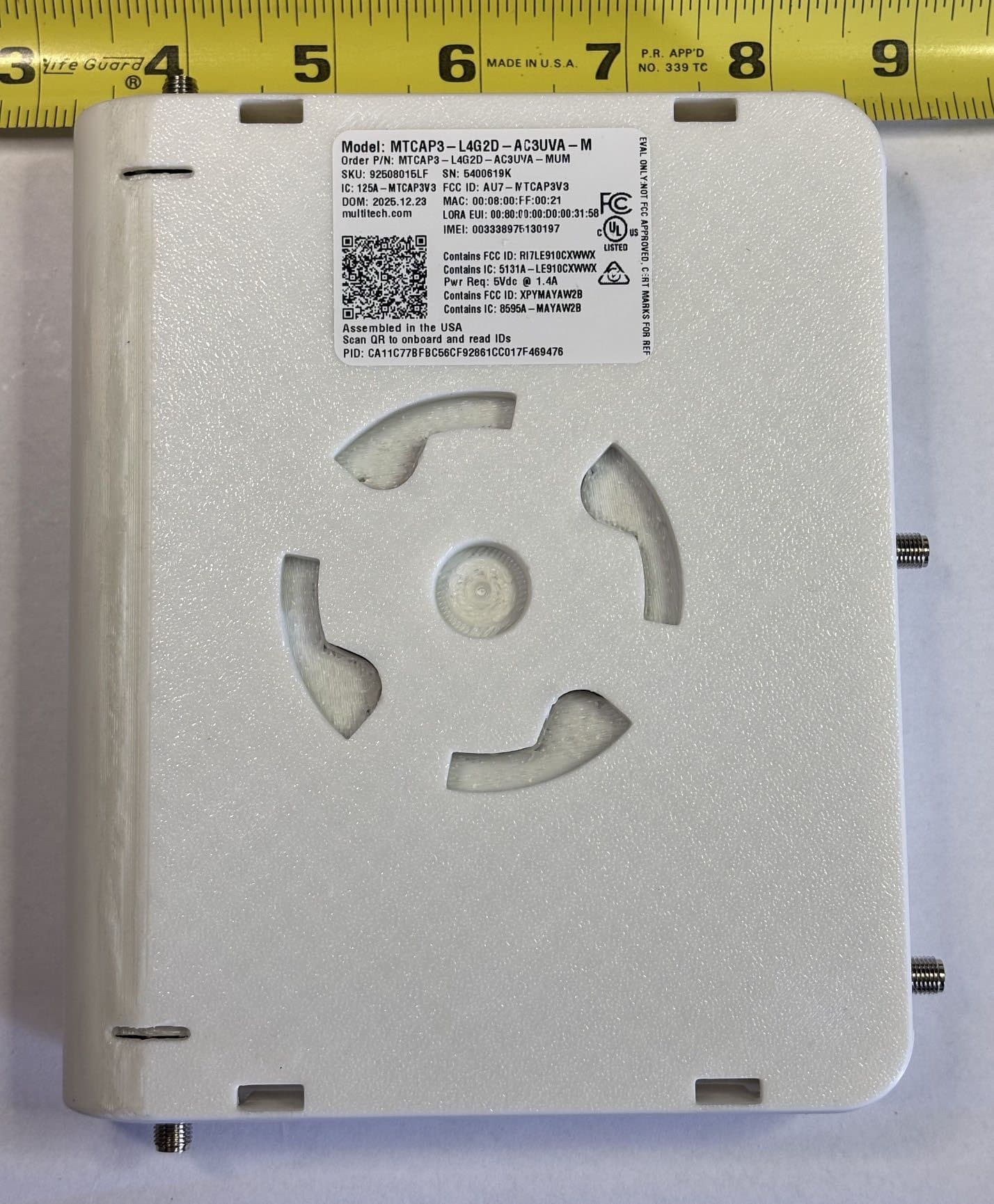
AU7-MTCAP3V3
Jun 17, 2026MTCAP3-L4G2D-AC3UVA-M, MTCAP3-L4G2D-AC3UWA-M
Equipment Class
DTS - Digital Transmission System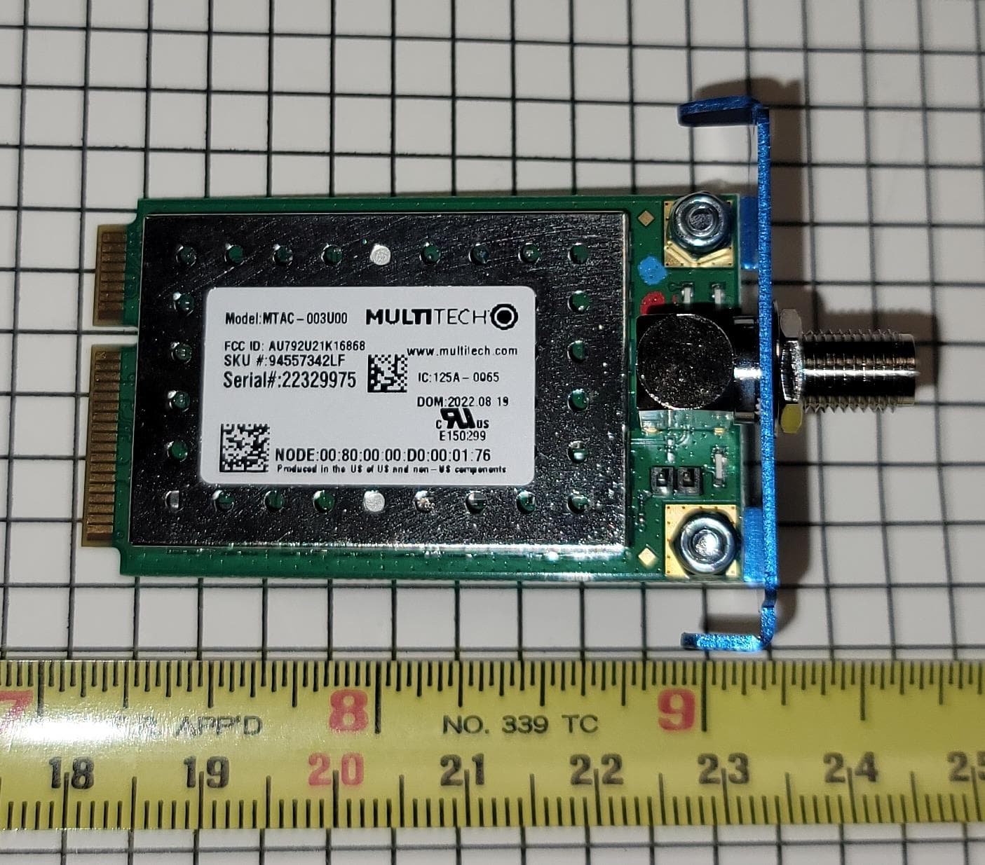
AU792U21K16868
Sep 24, 2023MTAC-003U00
Equipment Class
DTS - Digital Transmission System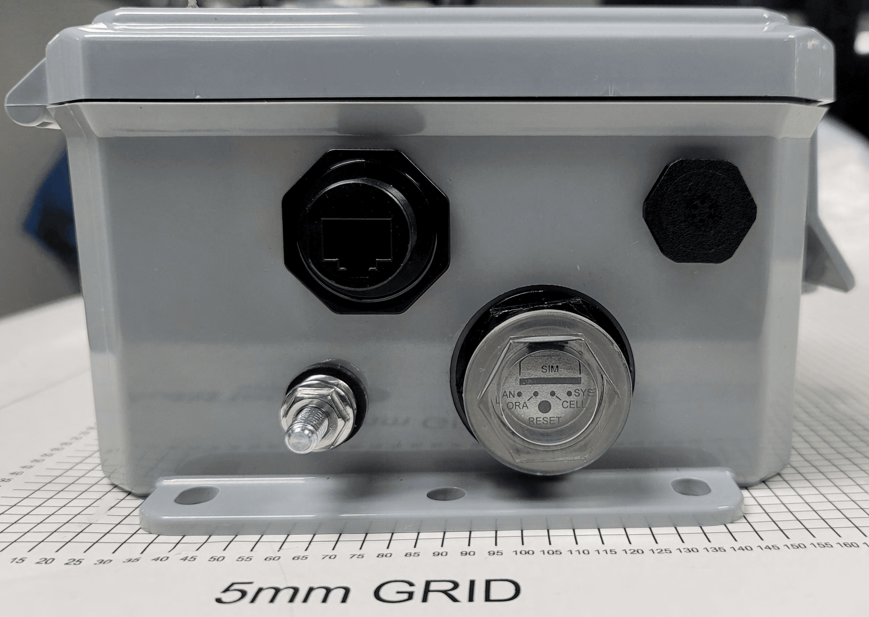
AU792U21B10865
Oct 04, 2021MTCDTIP2
Equipment Class
DTS - Digital Transmission System
AU792U19K19864
Mar 03, 2020MTCAP2-915
Equipment Class
DTS - Digital Transmission System
AU792U13A16856
Apr 26, 2015MTAC-Lora-915
Equipment Class
DTS - Digital Transmission System