AU792U21K16868MTAC-003U00
Multi Tech Systems Inc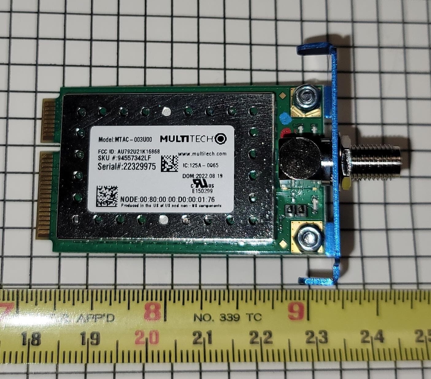
Click to zoom
Application Details
- Equipment Class
- DTS - Digital Transmission System
- Date of Grant
- Sep 24, 2023
- Application Purpose
- Original Equipment
- Date of Application
- Sep 24, 2023
- Equipment Note
- MTAC-003U00
- Frequency Range
- 923.30000000 - 927.50000000
- Company
- Multi Tech Systems Inc
- Country
- United States
Documents & Files
Document Text
Text extracted from the exhibit documents filed with the FCC. Open a document above to read the original.
Users Manual
MTAC-003GatewayAccessory CardHardwareGuide MTAC-003 GATEWAY ACCESSORY CARD HARDWARE GUIDE 2MTAC-003 Gateway Accessory Card Hardware Guide MTAC-003 Gateway Accessory Card Hardware Guide Models: MTAC-003 Part Number: S000799, Version 1.4 09/14/2023 Copyright This publication may not be reproduced, in whole or in part, without the specific and express prior written permission signed by an executive officer of Multi-Tech Systems, Inc. All rights reserved. Copyright © 2022 by Multi-Tech Systems, Inc. Multi-Tech Systems, Inc. makes no representations or warranties, whether express, implied or by estoppels, with respect to the content, information, material and recommendations herein and specifically disclaims any implied warranties of merchantability, fitness for any particular purpose and non- infringement. Multi-Tech Systems, Inc. reserves the right to revise this publication and to make changes from time to time in the content hereof without obligation of Multi-Tech Systems, Inc. to notify any person or organization of such revisions or changes. Trademarks and Registered Trademarks MultiTech and the MultiTech logo are trademarks and registered trademarks of Multi-Tech Systems, Inc. All other products and technologies are the trademarks or registered trademarks of their respective holders. Legal Notices The MultiTech products are not designed, manufactured or intended for use, and should not be used, or sold or re-sold for use, in connection with applications requiring fail-safe performance or in applications where the failure of the products would reasonably be expected to result in personal injury or death, significant property damage, or serious physical or environmental damage. Examples of such use include life support machines or other life preserving medical devices or systems, air traffic control or aircraft navigation or communications systems, control equipment for nuclear facilities, or missile, nuclear, biological or chemical weapons or other military applications (“Restricted Applications”). Use of the products in such Restricted Applications is at the user’s sole risk and liability. MULTITECH DOES NOT WARRANT THAT THE TRANSMISSION OF DATA BY A PRODUCT OVER A CELLULAR COMMUNICATIONS NETWORK WILL BE UNINTERRUPTED, TIMELY, SECURE OR ERROR FREE, NOR DOES MULTITECH WARRANT ANY CONNECTION OR ACCESSIBILITY TO ANY CELLULAR COMMUNICATIONS NETWORK. MULTITECH WILL HAVE NO LIABILITY FOR ANY LOSSES, DAMAGES, OBLIGATIONS, PENALTIES, DEFICIENCIES, LIABILITIES, COSTS OR EXPENSES (INCLUDING WITHOUT LIMITATION REASONABLE ATTORNEYS FEES) RELATED TO TEMPORARY INABILITY TO ACCESS A CELLULAR COMMUNICATIONS NETWORK USING THE PRODUCTS. The MultiTech products and the final application of the MultiTech products should be thoroughly tested to ensure the functionality of the MultiTech products as used in the final application. The designer, manufacturer and reseller has the sole responsibility of ensuring that any end user product into which the MultiTech product is integrated operates as intended and meets its requirements or the requirements of its direct or indirect customers. MultiTech has no responsibility whatsoever for the integration, configuration, testing, validation, verification, installation, upgrade, support or maintenance of such end user product, or for any liabilities, damages, costs or expenses associated therewith, except to the extent agreed upon in a signed written document. To the extent MultiTech provides any comments or suggested changes related to the application of its products, such comments or suggested changes is performed only as a courtesy and without any representation or warranty whatsoever. Contacting MultiTech CountrySalesSupport Europe, Middle East, Africa: [email protected]+(44) 118 959 [email protected]+(44) 118 959 7774 U.S., Canada, all others: [email protected](800) 328-9717 or (763) 785-3500 [email protected](800) 972-2439 or (763) 717-5863 Website www.multitech.com Knowledge Base For immediate access to support information and resolutions for MultiTech products, visithttp://www.multitech.com/kb.go. Support Portal To create an account and submit a support case directly to our technical support team, visit:https://support.multitech.com. Warranty To read the warranty statement for your product, visithttps://www.multitech.com/legal/warranty. World Headquarters Multi-Tech Systems, Inc. 2205 Woodale Drive, Mounds View, MN 55112 CONTENTS MTAC-003 Gateway Accessory Card Hardware Guide3 Contents Chapter 1 – Overview .............................................................................................................................................. 5 Introduction .................................................................................................................................................................. 5 Documentation ............................................................................................................................................................. 5 Product Build Options................................................................................................................................................... 6 Installing the Accessory Card ........................................................................................................................................ 6 Using Two LoRa Gateway Accessory Cards................................................................................................................... 6 Chapter 2 – Hardware and Specifications................................................................................................................. 7 Hardware Specifications ............................................................................................................................................... 7 LoRa Transmission Output Power for MTAC-003 .......................................................................................................…
Text truncated - open the document above for the full version.
Attestation Statements
Multi-Tech Systems, Inc. 2205 Woodale Drive • Mounds View, Minnesota 55112 U.S.A. (763) 785-3500 or (800) 328-9717 • Fax (763) 785-9874 www.multitech.com U.S. Agent for Service of Process Attestation To the attention of Federal Communications Commission Authorization and Evaluation Division 7435 Oakland Mills Road Columbia, Maryland 21046 Re: section 2.911(d)(7) filing This letter is to confirm that the Applicant has designated itself as the U.S Agent for service of process as required by §2.911(d)(7). The Applicant further acknowledges acceptance to maintain an agent for no less than one year after the grantee has terminated all marketing and importation or the conclusion of any Commission-related proceeding involving the equipment. Applicant / Designated U.S Agent Company Name: Multi Tech Systems Inc Grantee Code or FCC ID: AU792U21K16868 FRN: 0009336579 Contact Name: Tim Gunn Street Address: 2205 Woodale Drive, Mounds View, MN 55112 U.S.A City/Province/Zip: Mounds View, Minnesota, 55112 Telephone No: 763-717-5501 Email: [email protected] Applicant / U.S. Agent Signature: Date: 2023-08 -21 Signed by (printed name): Tim Gunn
Attestation Statements
Multi-Tech Systems, Inc. 2205 Woodale Drive • Mounds View, Minnesota 55112 U.S.A. (763) 785-3500 or (800) 328-9717 • Fax (763) 785-9874 www.multitech.com Date: 2023-09-13 FCC ID: AU792U21K16868 To the attention of Federal Communications Commission Authorization and Evaluation Division Attestation Statements Attestation Statements Part 2.911(d)(5)(i) Filing Multi Tech Systems Inc certifies that the equipment for which authorization is sought is not “covered” equipment prohibited from receiving an equipment authorization pursuant to section 2.903 of the FCC rules. Attestation Statements Part 2.911(d)(5)(ii) Filing Multi Tech Systems Inc certifies that, as of the date of the filing of the application, the applicant is not identified on the Covered List as an entity producing “covered” equipment. Sincerely yours, ----------------------------------------------- Tim Gunn, Director of Certifications and Product Support Multi Tech Systems Inc Tel: 763-717-5501 Fax: 763-717-5854 E-mail: [email protected]
Cover Letter(s)
To Whom It May Concern: 06/13/2023 Federal Communications Commission Equipment Authorization Branch 7435 Oakland Mills Road Columbia, MD 21046 WE, MULTI-TECH SYSTEMS INC., 2205 Woodale Dr., Mounds View Minnesota 55112 United States, are seeking original FCC certification under the following parts: FCC 15.247 FCC ID is AU792U21K16868 The MTAC-003U00 is a Lora device, operating in the ISM band (902-928 MHz). It contains a LoRa transceiver. The current evaluation covers the LoRa transceiver on the downlink band 923.3-927.5 MHz. The MTAC-003-U00 is intended to be used only, in two different Multi-Tech Gateway designs. One gateway design will use the R-SMA for Antenna connections and the other design will have the MTAC-003U00 embedded into an outdoor IP67 gateway that will use an external N-Type connector for the Antenna. The IP67 Gateway requires professional install due to how it must be mounted on rooftops and tall poles or cell towers and requires experienced people to get it installed correctly in those settings. The MTAC-003U00 is not intended to be designed into 3 rd party Gateways as this would be competing against our own products. Sincerely, Tim Gunn - 06/13/2023 Director of Certifications Multi-Tech Systems, Inc
Cover Letter(s)
02/07/2023 Federal Communications Commission Authorization and Evaluation Division 7435 Oakland Mills Road Columbia, Maryland 21046 Re: Request for confidentiality FCC ID: AU792U21K16868 To whom it may concern, We hereby respectfully request that under the provision of 47 CFR 0.459 and 0.457(d) the documents listed below and attached with this application for certification be provided with confidential status. • Schematics.pdf • Operational Description.pdf • Frequency Block Diagrams.pdf Any exhibit / information for which we have requested confidentiality, but which may not be accorded such treatment by the FCC, should be returned to us. The documents listed above contain trade secrets that are treated as confidential by us. Substantial competitive harm to us could result should they be made available to the public. Sincerely, Tim Gunn Director of Certifications and Product Support
ID Label/Location Info
Label applied with adhesive back, 5095 performance Resin with Z-Ultimate 3000 Sliver or White Multi-Tech will be labelling the Gateway that MTAC-003U00 gets installed into at time of manufacture of the Gateway, with the “Contains FCC ID AU792U21K16868”
RF Exposure Info
This report must not be used to claim product certification, approval, or endorsement by A2LA or any agency of the U.S. Government. This Report shall not be reproduced, except in full without written approval of the laboratory. Multi-Tech Systems, Inc. MTAC-003U00 FCC 1.1307:2023 902 – 928MHz Wideband (DTS) Transceiver Radio Report: MLTI0249.7, Issue Date: January 26, 2023 CERTIFICATE OF EVALUATION 2018-09-14 Product compliance is the responsibility of the client; therefore, the tests and equipment modes of operation represented in this report were agreed upon by the client, prior to testing. The results of this test pertain only to the sample(s) tested. The specific description is noted in each of the individual sections of the test report supporting this certificate of test. This report reflects only those tests from the referenced standards shown in the certificate of test. It does not include inspection or verification of labels, identification, marking or user information. As indicated in the Statement of Work sent with the quotation, Element’s standard process is to always use the latest published version of the test methods even when earlier versions are cited in the test specification. Issuance of a purchase order was de facto acceptance of this approach. Otherwise, the client would have advised Element in writing of the specific version of the test methods they wanted applied to the subject testing Last Date of Evaluation: January 25, 2023 Multi-Tech Systems, Inc. EUT: MTAC-003U00 RF Exposure Evaluation Standards Specification Method FCC 1.1307:2023 FCC 1.1307:2023 Results Method Clause Description Applied Results Comments (b)(3)(i)(B) Exemption From RF Exposure Evaluation Yes Pass N/A Deviations From Evaluation Standards None Approved By: Donald Facteau, Process Architect Report No. MLTI0249.72/11 REVISION HISTORY 2018.07.17 Revision Number Description Date (yyyy-mm-dd) Page Number 00 None Report No. MLTI0249.73/11 ACCREDITATIONS AND AUTHORIZATIONS 2021.09.01 United States FCC - Designated by the FCC as a Telecommunications Certification Body (TCB). Certification chambers, Open Area Test Sites, and conducted measurement facilities are listed with the FCC. A2LA - Each laboratory is accredited by A2LA to ISO / IEC 17025, and as a product certifier to ISO / IEC 17065 which allows Element to certify transmitters to FCC and IC specifications. Canada ISED - Recognized by Innovation, Science and Economic Development Canada as a Certification Body (CB) and as a CAB for the acceptance of test data. European Union European Commission – Recognized as an EU Notified Body validated for the EMCD and RED Directives. United Kingdom BEIS – Recognized by the UK as an Approved Body under the UK Radio Equipment and UK EMC Regulations. Australia/New Zealand ACMA - Recognized by ACMA as a CAB for the acceptance of test data. Korea MSIT / RRA - Recognized by KCC’s RRA as a CAB for the acceptance of test data. Japan VCCI - Associate Member of the VCCI. Conducted and radiated measurement facilities are registered. Taiwan BSMI – Recognized by BSMI as a CAB for the acceptance of test data. NCC - Recognized by NCC as a CAB for the acceptance of test data. Singapore IDA – Recognized by IDA as a CAB for the acceptance of test data. Israel MOC – Recognized by MOC as a CAB for the acceptance of test data. Hong Kong OFCA – Recognized by OFCA as a CAB for the acceptance of test data. Vietnam MIC – Recognized by MIC as a CAB for the acceptance of test data. SCOPE For details on the Scopes of our Accreditations, please visit: California Minnesota Oregon Texas Washington Report No. MLTI0249.74/11 FACILITIES 2020.12.15 California Labs OC01-17 41 Tesla Irvine, CA 92618 (949) 861-8918 Minnesota Labs MN01-11 9349 W Broadway Ave. Brooklyn Park, MN 55445 (612)-638-5136 Oregon Labs EV01-12 6775 NE Evergreen Pkwy #400 Hillsboro, OR 97124 (503) 844-4066 Texas Labs TX01-09 3801 E Plano Pkwy Plano, TX 75074 (469) 304-5255 Washington Labs NC01-05 19201 120 th Ave NE Bothell, WA 98011 (425)984-6600 A2LA Lab Code: 3310.04 Lab Code: 3310.05 Lab Code: 3310.02 Lab Code: 3310.03 Lab Code: 3310.06 Innovation, Science and Economic Development Canada 2834B-1, 2834B-3 2834E-1, 2834E-3 2834D-1 2834G-1 2834F-1 BSMI SL2-IN-E-1154R SL2-IN-E-1152R SL2-IN-E-1017 SL2-IN-E-1158R SL2-IN-E-1153R VCCI A-0029 A-0109 A-0108 A-0201 A-0110 Recognized Phase I CAB for ISED, ACMA, BSMI, IDA, KCC/RRA, MIC, MOC, NCC, OFCA US0158 US0175 US0017 US0191 US0157 Report No. MLTI0249.75/11 PRODUCT DESCRIPTION 2018-07-17 Client and Equipment Under Evaluation Information Company Name: Multi-Tech Systems, Inc. Address: 2205 Woodale Dr City, State, Zip: Mounds View, MN 55112 Evaluation Requested By: Michael Kwilinski EUT: MTAC-003U00 Date of Evaluation: 1/25/2023 Information Provided by the Party Requesting the Evaluation Functional Description of the Equipment: The MTAC-003U00 gateway accessory card enables long range connectivity to distributed assets and sensors using the latest RF spread spectrum (LoRa) technology. Objective: To demonstrate compliance with FCC Requirements for RF exposure for 1.1307 RF exempt devices Report No. MLTI0249.76/11 RF EXPOSURE CONDITION 2018-07-17 The following RF Exposure conditions were used for the assessment documented in this report: Intended Use Mobile Location on Body (if applicable) NA How is the Device Used Device is used at a distance greater than 20cm. Radios Contained in the Same Host Device DTS Simultaneous Transmitting Radios None Body Worn Accessories N/A Environment General Population/Uncontrolled Exposure Report No. MLTI0249.77/11 EXEMPTION FROM RF EXPOSURE EVALUATION EXRPT.2022.07.12.0 OVERVIEW With respect to the limits on human exposure to RF emissions provided in 47 CFR §1.1310, if equipment can be shown to qualify for an exemption pursuant to 47 CFR §1.1307(b)(3), an evaluation is not required. COMPLIANCE WITH FCC 1.1310 Per 1.1307(b)(3), (i) For single RF sources (i.e., any single fixed RF source, mobile device, …
Text truncated - open the document above for the full version.
Test Report
This report must not be used to claim product certification, approval, or endorsement by A2LA or any agency of the U.S. Government. This Report shall not be reproduced, except in full without written approval of the laboratory. Multi-Tech Systems, Inc. Antenna PCTEL PN MFB9155NF Antenna Pattern Measurements Report: MLTI0281, Issue Date: February 23, 2023 Approved by: Eric Brandon, Department Manager REVISION HISTORY 2018.07.17 Revision Number Description Date (yyyy-mm-dd) Page Number 00 None Report No. MLTI02812/9 ACCREDITATIONS AND AUTHORIZATIONS 2021.09.01 United States FCC - Designated by the FCC as a Telecommunications Certification Body (TCB). Certification chambers, Open Area Test Sites, and conducted measurement facilities are listed with the FCC. A2LA - Each laboratory is accredited by A2LA to ISO / IEC 17025, and as a product certifier to ISO / IEC 17065 which allows Element to certify transmitters to FCC and IC specifications. Canada ISED - Recognized by Innovation, Science and Economic Development Canada as a Certification Body (CB) and as a CAB for the acceptance of test data. European Union European Commission – Recognized as an EU Notified Body validated for the EMCD and RED Directives. United Kingdom BEIS – Recognized by the UK as an Approved Body under the UK Radio Equipment and UK EMC Regulations. Australia/New Zealand ACMA - Recognized by ACMA as a CAB for the acceptance of test data. Korea MSIT / RRA - Recognized by KCC’s RRA as a CAB for the acceptance of test data. Japan VCCI - Associate Member of the VCCI. Conducted and radiated measurement facilities are registered. Taiwan BSMI – Recognized by BSMI as a CAB for the acceptance of test data. NCC - Recognized by NCC as a CAB for the acceptance of test data. Singapore IDA – Recognized by IDA as a CAB for the acceptance of test data. Israel MOC – Recognized by MOC as a CAB for the acceptance of test data. Hong Kong OFCA – Recognized by OFCA as a CAB for the acceptance of test data. Vietnam MIC – Recognized by MIC as a CAB for the acceptance of test data. SCOPE For details on the Scopes of our Accreditations, please visit: California Minnesota Oregon Texas Washington Report No. MLTI02813/9 FACILITIES 2020.12.15 California Labs OC01-17 41 Tesla Irvine, CA 92618 (949) 861-8918 Minnesota Labs MN01-11 9349 W Broadway Ave. Brooklyn Park, MN 55445 (612)-638-5136 Oregon Labs EV01-12 6775 NE Evergreen Pkwy #400 Hillsboro, OR 97124 (503) 844-4066 Texas Labs TX01-09 3801 E Plano Pkwy Plano, TX 75074 (469) 304-5255 Washington Labs NC01-05 19201 120 th Ave NE Bothell, WA 98011 (425)984-6600 A2LA Lab Code: 3310.04 Lab Code: 3310.05 Lab Code: 3310.02 Lab Code: 3310.03 Lab Code: 3310.06 Innovation, Science and Economic Development Canada 2834B-1, 2834B-3 2834E-1, 2834E-3 2834D-1 2834G-1 2834F-1 BSMI SL2-IN-E-1154R SL2-IN-E-1152R SL2-IN-E-1017 SL2-IN-E-1158R SL2-IN-E-1153R VCCI A-0029 A-0109 A-0108 A-0201 A-0110 Recognized Phase I CAB for ISED, ACMA, BSMI, IDA, KCC/RRA, MIC, MOC, NCC, OFCA US0158 US0175 US0017 US0191 US0157 Report No. MLTI02814/9 PRODUCT DESCRIPTION 2018-07-17 Client and Equipment under Test (EUT) Information Company Name: Multi-Tech Systems, Inc. Address: 2205 Woodale Drive City, State, Zip: Saint Paul, MN 55112 Test Requested By: Tim Gunn EUT: Antenna PCTEL PN MFB9155NF First Date of Test: November 18, 2022 Last Date of Test: November 18, 2022 Receipt Date of Samples: November 18, 2022 Equipment Design Stage: Production Equipment Condition: No Damage Purchase Authorization: Verified Information Provided by the Party Requesting the Test Functional Description of the EUT: The mCard™ gateway accessory cards provide the flexibility needed to manage a wide range of different wired and wireless interfaces and associated communication protocols required to connect sensors, appliances, and assets to the Conduit® programmable gateway. Testing Objective: To obtain 3D antenna pattern measurements and calculated antenna performance values EUT Photo: Report No. MLTI02815/9 MODIFICATIONS 2018-07-17 Equipment Modifications Item Date Test Modification Note Disposition of EUT 1 2022-11-18 Active 3D Antenna Pattern Measurements Tested as delivered to Test Station. No EMI suppression devices were added or modified during this test. Scheduled testing was completed. Report No. MLTI02816/9 description OTA 2018.01.04 TEST EQUIPMENT IDInterval OTA36 mo R32918 mo TEST DESCRIPTION PASSIVE 3D ANTENNA PATTERN MEASUREMENTS Network AnalyzerKeysight TechnologiesAGIL-E5071C-PKG 103/22/2022 Chamber - OTAETS LindgrenAMS-8923-1954/19/2021 ManufacturerModel Testing was performed using the mode(s) of operation and configuration(s) noted within the report. The individuals and/or the organization requesting the test provided the modes, configurations and settings used to complete the evaluation. The actual test parameters are specified in the test data, this includes items such as investigated frequency range (scanned) and test levels. The testing methods and performance specifications, as well as the test site used for the evaluation are indicated in the test data. The test data represents the configuration / operating mode/ model that produced the highest emission levels as compared to the specification limit. DescriptionLast Cal. Using the modes of operation and configurations noted within this report, a radiated pattern measurement test was performed. The frequency ranges investigated (scanned), are also noted in this report. The EUT was placed on a low dielectric constant support structure (Phi Axis Positioner) in the 3D center of the measurement zone using a laser alignment system. The antenna port of the EUT is connected to an RF feed cable which is connected to a Vector Network Analyzer (VNA) at its opposite end. The test begins with a measurement path configured (via ETS-Lindgren EMQuest Data Acquisition and Analysis Software) such that an electrical path is present from the Theta polarization element of the -165° detector antenna, to port 2 of th…
Text truncated - open the document above for the full version.
Test Report
Description: 868-928MHz Swivel Type dipole antenna PART NUMBER: W1063/ W1063M Series: Stick Antenna Issue: 1837 In the effort to improve our products, we reserve the right to make changes judged to be necessary. CONFIDENTIAL AND PROPRIETARY INFORMATION This document contains confidential and proprietary information ofPulse Electronics, Inc. (Pulse) and is protected by copyright, trade secret and other state and federal laws. Its receipt or possession does not convey any rights to reproduce, disclose its contents, or to manufacture, use or sell anything it may describe. Reproduction, disclosure or use without specific written authorization of Pulse is strictly forbidden. For more information: Pulse Worldwide HeadquartersPulse/Larsen AntennasEurope HeadquartersPulse (Suzhou) Wireless Products Co, Inc. 15255 Innovation Drive #100Pulse GmbH & Do, KG99 HuoJuRoad(#29 Bldg,4 th Phase San Diego, CA 92128Vancouver, WA 98683Zeppelinstrasse15Suzhou New District USAUSAHerrenberg, Germany Jiangsu Province, Suzhou 215009 PR China Tel:1-858-674-8100Tel: 1-360-944-7551 - Tel: 49 7032 7806 0 Tel: 86 512 6807 9998 18110 SE 34 th St Bldg2 Suite 250 Features: Applications: All dimensions are in mm •Frequency 868-928MHz •Gain 1dBi •Efficiency 70% •Length 195mm straight •Connectors: •W1063 RP-SMA Male •W1063M SMA Male •RoHS Compliant •Indoor use •868MHz and 915MHz ISM band radios •IoT devices •Security •Sensors •Monitoring 1 Issue: 1837 In the effort to improve our products, we reserve the right to make changes judged to be necessary. CONFIDENTIAL AND PROPRIETARY INFORMATION This document contains confidential and proprietary information ofPulse Electronics, Inc. (Pulse) and is protected by copyright, trade secret and other state and federal laws. Its receipt or possession does not convey any rights to reproduce, disclose its contents, or to manufacture, use or sell anything it may describe. Reproduction, disclosure or use without specific written authorization of Pulse is strictly forbidden. Series: Stick Antenna Description: 868-928MHz Swivel Type dipole antenna PART NUMBER: W1063/ W1063M 2 Frequency 863-928 MHz NominalImpedance50 VSWR 2 Maximum Radiation PatternOmni Gain1 dBi Efficiency70 % PolarizationLinear Power Withstanding1 W Overall Length 195+/-2 mm Weight 23.5 g Antenna Color / Material Black Connector type W1063 RP SMA Male W1063M SMA Male IP RatingIP20, Indoor use Operating Temperature -20 °C /+65 °C Storage Temperature -30 °C /+75 °C MECHANICALSPECIFICATIONS ENVIRONMENTAL SPECIFICATIONS ELECTRICAL SPECIFICATIONS Issue: 1837 In the effort to improve our products, we reserve the right to make changes judged to be necessary. CONFIDENTIAL AND PROPRIETARY INFORMATION This document contains confidential and proprietary information ofPulse Electronics, Inc. (Pulse) and is protected by copyright, trade secret and other state and federal laws. Its receipt or possession does not convey any rights to reproduce, disclose its contents, or to manufacture, use or sell anything it may describe. Reproduction, disclosure or use without specific written authorization of Pulse is strictly forbidden. Series: Stick Antenna Description: 868-928MHz Swivel Type dipole antenna PART NUMBER: W1063/ W1063M 3 MECHANICALDRAWING All dimensions are in mm Issue: 1837 In the effort to improve our products, we reserve the right to make changes judged to be necessary. CONFIDENTIAL AND PROPRIETARY INFORMATION This document contains confidential and proprietary information ofPulse Electronics, Inc. (Pulse) and is protected by copyright, trade secret and other state and federal laws. Its receipt or possession does not convey any rights to reproduce, disclose its contents, or to manufacture, use or sell anything it may describe. Reproduction, disclosure or use without specific written authorization of Pulse is strictly forbidden. Series: Stick Antenna Description: 868-928MHz Swivel Type dipole antenna PART NUMBER: W1063/ W1063M 4 TEST SETUP Z X Y Issue: 1837 In the effort to improve our products, we reserve the right to make changes judged to be necessary. CONFIDENTIAL AND PROPRIETARY INFORMATION This document contains confidential and proprietary information ofPulse Electronics, Inc. (Pulse) and is protected by copyright, trade secret and other state and federal laws. Its receipt or possession does not convey any rights to reproduce, disclose its contents, or to manufacture, use or sell anything it may describe. Reproduction, disclosure or use without specific written authorization of Pulse is strictly forbidden. Series: Stick Antenna Description: 868-928MHz Swivel Type dipole antenna PART NUMBER: W1063/ W1063M CHARTS 5 VSWR Issue: 1837 In the effort to improve our products, we reserve the right to make changes judged to be necessary. CONFIDENTIAL AND PROPRIETARY INFORMATION This document contains confidential and proprietary information ofPulse Electronics, Inc. (Pulse) and is protected by copyright, trade secret and other state and federal laws. Its receipt or possession does not convey any rights to reproduce, disclose its contents, or to manufacture, use or sell anything it may describe. Reproduction, disclosure or use without specific written authorization of Pulse is strictly forbidden. Series: Stick Antenna Description: 868-928MHz Swivel Type dipole antenna PART NUMBER: W1063/ W1063M CHARTS 6 Efficiency(%) Issue: 1837 In the effort to improve our products, we reserve the right to make changes judged to be necessary. CONFIDENTIAL AND PROPRIETARY INFORMATION This document contains confidential and proprietary information ofPulse Electronics, Inc. (Pulse) and is protected by copyright, trade secret and other state and federal laws. Its receipt or possession does not convey any rights to reproduce, disclose its contents, or to manufacture, use or sell anything it may describe. Reproduction, disclosure or use without specific written authorization of Pulse is strictly forbidden. Series: Stick Antenna Description: 868-928MHz Swivel …
Text truncated - open the document above for the full version.
Test Report
INFRASTRUCTURE ANTENNAS PCTEL, Inc. WEB: www.antenna.com PCTEL’s MFB 900/800 MHz series are base matched half wave antennas encapsulated in heavy-duty fiberglass radomes with a thick-walled aluminum mounting base for reliable long term use. All models are DC grounded and UPS shippable. Features • White UV-resistant pultruded fiberglass radome • Thick-walled aluminum mounting base • Unity, 3 dB, 5 dB, 7 dB models • Temperature range -40⁰C to +85⁰C • UPS shippable • Factory tuned PCTEL 800/900 MHz Fiberglass Base Station Omnidirectional Antennas MFB Series * (NF) indicates optional N Female connector. Omnidirectional Fiberglass Antennas - Cellular Vented STANDARD CONFIGURATION ModelCableConnectorMount MFBW7463N/AN Female Mast or wall mounted. Mount options for all models: (sold separately) MMK4: heavy-duty mast mount MMK9: aluminum mast mount for 1-5/16” OD antennas MBSWM: wall mounting bracket for antennas over 30” (two are required) MMK12: heavy-duty mount bracket MFB8133N/AN Female MFB8583N/AN Female MFB8965NF2 ft RG213N Female MFB9153N/AN Female MFB9155(NF)*2 ft RG213N Male MFB9157(NF)*2 ft RG213N Male MFB9153 MECHANICAL & ENVIRONMENTAL SPECIFICATIONS ModelWeightHeight Bending Moment at Rated Wind (lbf ) Lateral Thrust at Rated Wind (lbf-ft) Equivalent Flat Plate Area Rated Wind MFBW74631.50 lbs (0.68 kg)27 in (68.5 cm)16.913.5.17 sq ft125 mph MFB81331.25 lbs (0.57 kg)28 in (71.0 cm)14.512.5.12 sq ft125 mph MFB85831.25 lbs (0.57 kg)28…
Text truncated - open the document above for the full version.
Contact Information
Applicant
Tim Gunn(Director of Certifications and Product Support)
Test Firm
Element Materials Technology Minneapolis - BrooklyRenee Walker
[email protected]503 844 4066
Technical Specifications
| # | Rule Parts | Frequency Range | Power Output |
|---|---|---|---|
| 1 | 15C | 923.3 MHz - 927.5 MHz | 550.00 mW |
Other Applications from Multi Tech Systems Inc
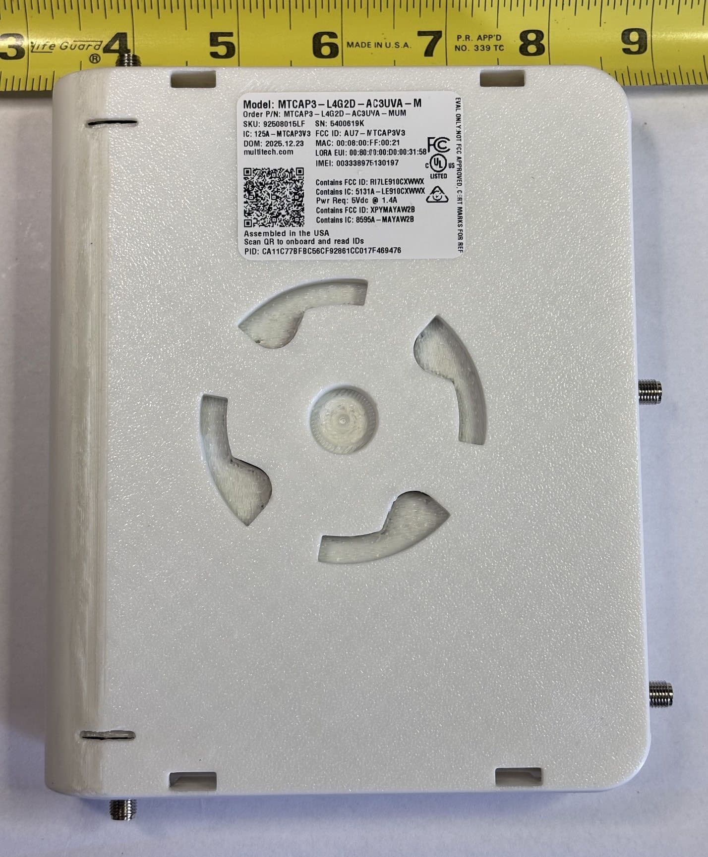
AU7-MTCAP3V3
Jun 17, 2026MTCAP3-L4G2D-AC3UVA-M, MTCAP3-L4G2D-AC3UWA-M
Equipment Class
DTS - Digital Transmission System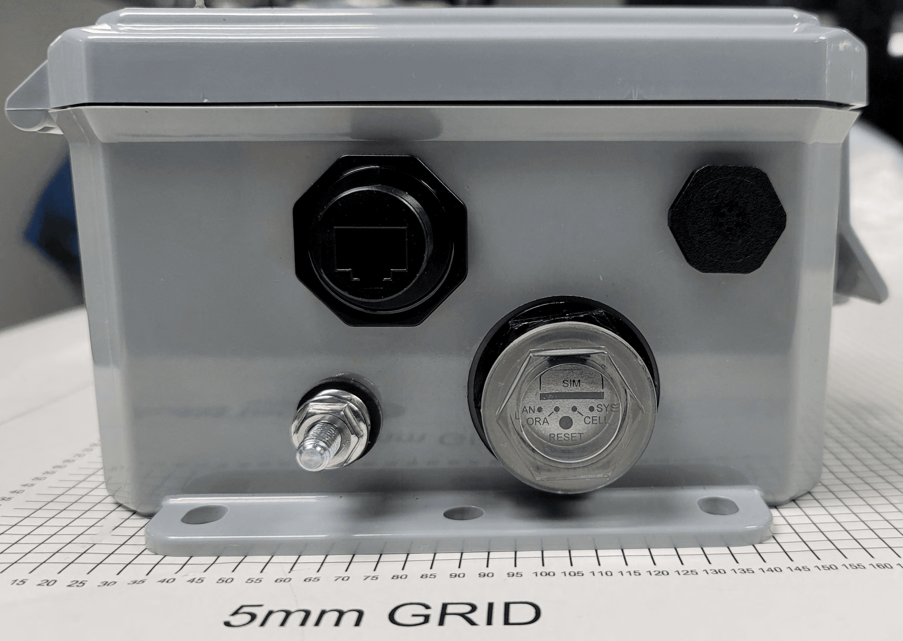
AU792U21B10865
Oct 04, 2021MTCDTIP2
Equipment Class
DTS - Digital Transmission System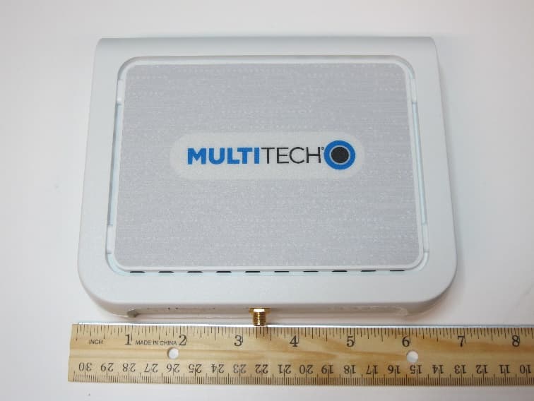
AU792U19K19864
Mar 03, 2020MTCAP2-915
Equipment Class
DTS - Digital Transmission System
AU792U13A16856
Apr 26, 2015MTAC-Lora-915
Equipment Class
DTS - Digital Transmission System
AU792U13A16855
Jul 22, 2014MultiModem rCell 100 Series Router
Equipment Class
PCB - PCS Licensed Transmitter