AU792U07B06821Modular Transmitter
Multi Tech Systems Inc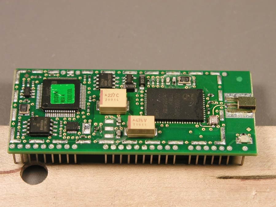
Click to zoom
Application Details
- Equipment Class
- DTS - Digital Transmission System
- Date of Grant
- Dec 17, 2007
- Application Purpose
- Original Equipment
- Date of Application
- Dec 12, 2007
- Equipment Note
- Modular Transmitter
- Frequency Range
- 2412.00000000 - 2462.00000000
- Company
- Multi Tech Systems Inc
- Country
- United States
Documents & Files
Document Text
Text extracted from the exhibit documents filed with the FCC. Open a document above to read the original.
Users Manual
Universal Socket Connectivity Embedded Device Networking Solutions Hardware Guide for Developers Copyright and Technical Support Multi-Tech Systems, Inc. Universal Socket Hardware Guide for Developers (S000342H) 2 Universal Socket Connectivity Hardware Guide for Developers, PN S000342H, Version H For the following products: SocketModem® – MT5600SMI SocketModem® – MT5656SMI SocketModem® – MT5634SMI SocketModem® – MT9234SMI SocketModem® – MT2492SMI SocketModem® – MT2456SMI-22 SocketModem® IP – MT2456SMI-IP SocketModem® IP – MT5656SMI-IP SocketEthernet IP® – MTXCSEM SocketEthernet IP® – MT100SEM SocketModem® ISDN – MT128SMI SocketModem® GPRS – MTSMC-G SocketModem® CDMA – MTSMC-C SocketModem® EDGE – MTSMC-E SocketWireless® Wi-Fi® – MT800SWM SocketWireless® Bluetooth® – MTS2BTSMI Copyright This publication may not be reproduced, in whole or in part, without prior expressed written permission from Multi- Tech Systems, Inc. All rights reserved. Copyright © 2004-7 by Multi-Tech Systems, Inc. Multi-Tech Systems, Inc. makes no representations or warranties with respect to the contents hereof and specifically disclaim any implied warranties of merchantability or fitness for any particular purpose. Furthermore, Multi-Tech Systems, Inc. reserves the right to revise this publication and to make changes from time to time in the content hereof without obligation of Multi-Tech Systems, Inc. to notify any person or organization of such revisions or changes. See the Multi-Tech Web site for current revisions of documentation. Trademarks Trademarks and Registered Trademarks of Multi-Tech Systems, Inc. are SocketModem, SocketWireless, SocketEthernet IP, and the Multi-Tech logo. Microsoft and Windows are trademarks or registered trademarks of Microsoft Corporation in the United States and other countries. Bluetooth is a registered trademark of the Bluetooth SIG, Inc. Wi-Fi is a registered trademark of the Wi-Fi Alliance. Patents This device covered by one or more of the following patents: 6,031,867; 6,012,113; 6,009,082; 5,905,794; 5,864,560; 5,815,567; 5,815,503; 5,812,534; 5,809,068; 5,790,532; 5,764,628; 5,764,627; 5,754,589; 5,724,356; 5,673,268; 5,673,257; 5,644,594; 5,628,030; 5,619,508; 5,617,423; 5,600,649; 5,592,586; 5,577,041; 5,574,725; 5,559,793; 5,546,448; 5,546,395; 5,535,204; 5,500,859; 5,471,470; 5,463,616; 5,453,986; 5,452,289; 5,450,425; 5,355,365; 5,309,562; 5,301,274. Other Patents Pending. World Headquarters Multi-Tech Systems, Inc. 2205 Woodale Drive Mounds View, Minnesota 55112 Phone: 763-785-3500 or 800-328-9717 Fax: 763-785-9874 Internet Address: http://www.multitech.com Technical Support Country By Email By Phone Europe, Middle East, Africa: [email protected] +(44) 118 959 7774 U.S., Canada, all others: [email protected] 800-972-2439 or 763-717-5863 Table of Contents Multi-Tech Systems, Inc. Universal Socket Hardware Guide for Developers (S000342H) 3 Table of Contents Chapter 1 - Universal Socket Connectivity ................................................................................................................ 5 Multi-Tech Embedded Solutions ......................................................................................................................... 5 Universal Socket Connectivity Features .......................................................................................................... 5 The Universal Socket Design........................................................................................................................... 5 Universal Developer Kit Contents .................................................................................................................... 6 AT Commands Are Included on the Developer CD ......................................................................................... 6 Universal Socket Configuration........................................................................................................................... 8 Universal Pin Descriptions ............................................................................................................................... 8 Design Considerations ....................................................................................................................................... 11 Noise Suppression Design Considerations.................................................................................................... 11 PC Board Layout Guidelines.......................................................................................................................... 11 Electromagnetic Interference (EMI) Considerations ...................................................................................... 12 Electrostatic Discharge Control...................................................................................................................... 12 Mechanicals and Schematics ............................................................................................................................ 13 Mechanical Dimensions in Inches.................................................................................................................. 13 Mechanical Dimensions in Millimeters ........................................................................................................... 14 Maximum Component Height........................................................................................................................ 14 SocketModem Developer Board .................................................................................................................... 15 Board Components ........................................................................................................................................ 16 Pins and Corresponding Signals.................................................................................................................... 16 Recommended Parts ..............................…
Text truncated - open the document above for the full version.
Cover Letter(s)
Multi-Tech Systems Inc. · 2205 Woodale Drive · Mounds View, Minnesota 55112 U.S.A. Telephone (763) 785-3500 or (800) 328-9717 - Fax (763) 785-9874 February 19, 2007 AmericanTCB 6731 Whittier Avenue McLean VA 22101 Attn: Director of Certification RE: FCC ID: AU792407B06821 / IC: 125A-0028 submittal as modular device 1. The modular transmitter must have its own RF shielding. This is intended to ensure that the module does not have to rely upon the shielding provided by the device into which it is installed in order for all modular transmitter emissions to comply with FCC Part 15 and Industry Canada limits. It is also intended to prevent coupling between the RF circuitry of the module and any wires or circuits in the device into which the module is installed. Such coupling may result in non-compliant operation. RF shielding is installed and shipped with the MT800SWM. See attached shield drawings (252b02M1 & 252b01M1). 2. The modular transmitter must have buffered modulation/data inputs (if such inputs are provided) to ensure that the module will comply with Part 15 and Industry Canada requirements under conditions of excessive data rates or over-modulation. MT800SWM packets are buffered in the LPC2138 before going in/out of UART for both RX and TX in the memory. 3. The modular transmitter must have its own power supply regulation. This is intended to ensure that the module will comply with Part 15 and Industry Canada requirements regardless of the design of the power supplying circuitry in the device into which the module is installed. The MT800SWM uses a voltage regulator in circuit. The regulator manufacture is MicroChip Technology, MFG’s P.N. TC1262-3.3VDB. 4. The modular transmitter must comply with the antenna requirements of FCC Sections 15.203 and 15.204(c) and Industry Canada requirements. The antenna must either be permanently attached or employ a “unique” antenna coupler (at all connections between the module and the antenna, including the cable). Any antenna used with the module must be approved with the module, either at the time of initial authorization or through a Class II permissive change. The “professional installation” provision of FCC Section 15.203 may not be applied to modules. The MT800SMW is supplied with a 6 inch reverse SMA to MMCS 50 ohm Coax cable. See drawing 209a03c1. 5. The modular transmitter must be tested in a stand-alone configuration, i.e., the module must not be inside another device during testing. This is intended to demonstrate that the module is capable of complying with FCC Part 15 and Industry Canada emission limits regardless of the device into which it is eventually installed. Unless the transmitter module will be battery powered, it must comply with the AC line conducted requirements found in FCC Section 15.207. AC or DC power lines and data input/output lines connected to the module must not contain ferrites, unless they will be marketed with the module (see FCC Section 15.27(a)). The length Multi-Tech Systems Inc. · 2205 Woodale Drive · Mounds View, Minnesota 55112 U.S.A. Telephone (763) 785-3500 or (800) 328-9717 - Fax (763) 785-9874 of these lines shall be length typical of actual use or, if that length is unknown, at least 10 centimeters to insure that there is no coupling between the case of the module and supporting equipment. Any accessories, peripherals, or support equipment connected to the module during testing shall be unmodified or commercially available (see FCC Section 15.31(i)). The MT800SMW was tested in a MultiTech development board in an open air environment. No shielding was part of the configuration, except for the necessary shielding as is required per FCC requirements for the module itself. 6. The modular transmitter must be labeled with its own FCC ID / IC number, and, if the FCC ID / IC number is not visible when the module is installed inside another device, then the outside of the device into which the module is installed must also display a label referring to the enclosed module. This exterior label can use wording such as the following: “Contains Transmitter Module FCC ID: XYZMODEL1 / IC: XXX-YYYY” or “Contains FCC ID: XYZMODEL1 / IC: XXX- YYYY.” Any similar wording that expresses the same meaning may be used. The Applicant may either provide such a label, an example of which must be included in the application for equipment authorization, or, must provide adequate instructions along with the module which explain this requirement. In the latter case, a copy of these instructions must be included in the application for equipment authorization. The FCC/IC ID is affixed to the module as per required. There is information provided in the MultiTech developers guided explaining the requirement that the ID be displayed on the exterior of the end device. 7. The modular transmitter must comply with any specific rule or operating requirements applicable to the transmitter and the manufacturer must provide adequate instructions along with the module to explain any such requirements. A copy of these instructions must be included in the application for equipment authorization. For example, there are very strict operational and timing requirements that must be met before a transmitter is authorized for operation under FCC Section 15.231 and Industry Canada specifications. For instance, data transmission is prohibited, except for operation under FCC Section 15.231(e), in which case there are separate field strength level and timing requirements. Compliance with these requirements must be assured. Transmit level is fixed and all necessary measurements have been made and recorded per FCC/IC requirements, as can be seen in the provided reports. 8. The modular transmitter must comply with any applicable RF exposure requirements. For example, FCC Rules in Sections 2.1091, 2.1093 and specific Sections of Part 15, including 15.319(i), 15.407(f), 15.253(f) and 15.255(g), require that Unlicensed PCS, UNII and millimeter wave devices perform…
Text truncated - open the document above for the full version.
External Photos
Multi-Tech MT800SWM - Top with Cover Multi-Tech MT800SWM - Top Multi-Tech MT800SWM - Bottom
ID Label/Location Info
Multi-Tech Model MT800SWM Label Multi-Tech Model MT800SWM Label Placement
Internal Photos
Multi-Tech MT800SWM - Top with Cover Multi-Tech MT800SWM - Top Multi-Tech MT800SWM - Bottom
RF Exposure Info
27 September 2007 AmericanTCB 6731 Whittier Avenue McLean VA 22101 Attn: Director of Certification RE: Declaration of Compliance to RF Exposure Limits for Humans Multi-Tech FCC ID: AU792U07B06821 RF Exposure Statement 1. Standard Applicable According to FCC 1.1307 (b)(1) and IC RSS-102, systems operating under the provisions of this section shall be operated in a manner that ensure that the public is not exposed to radio frequency energy level in excess of the Commission’s guideline. This is a mobile device operating in 2412-2462 MHz range. 2. Measurement Result: MPE calculations S = PG / 4πr 2 S = power density = .119 mw/cm 2 P = transmitter conducted power in milliwatts = 120 G = antenna numeric gain = 5 R = distance to radiation center in centimeters = 20 This is less than general population/uncontrolled exposure guideline of 1 mW/cm 2 . Joel T. Schneider Senior Engineer Minnesota Wild River Lab TÜV America Tel: 651 604 4582 [email protected]
Test Report
TÜV AMERICA INC 19333 Wild Mountain Road Taylors Falls MN 55084 Tel: (651) 638-0297 Fax: (651) 638-0298Rev. 012907 TEST RESULT SUMMARY FCC Part 15 Subpart C Sections 15.247 & 15.207 Industry Canada's RSS-210 Issue 7 & RSS-Gen Issue 2 MANUFACTURER'S NAME MultiTech Systems Incorporated MANUFACTURER'S ADDRESS 2205 Woodale Drive Mounds View MN 55112 NAME OF EQUIPMENT WLAN to Serial Module - 2.4 GHz DSSS MODEL NUMBER(S) TESTED MT800SWM TEST REPORT NUMBER WC705261 Rev A TEST DATE(S) 01 February, 16 - 17 July, 18 September 2007 According to testing performed at TÜV America Inc, the above mentioned unit is in compliance with the applicable electromagnetic compatibility (EMC) portions of the requirements defined in FCC Part 15 Subpart C Sections 15.247 and 15.207 and Industry Canada's RSS-210 Issue 7 and RSS-Gen Issue 2 It is the manufacturer's responsibility to assure that additional production units of this model are manufactured with identical electrical and mechanical characteristics. Any modifications necessary for compliance made during testing on the above mentioned date(s) must be implemented in all production units for compliance to be maintained. TÜV America Inc, as an independent testing laboratory, declares that the equipment tested as specified above conforms to the applicable EMC requirements of FCC Part 15 Subpart C Sections 15.247 “Operation within the bands 902–928 MHz, 2400–2483.5 MHz, and 5725–5850 MHz; General requirements.” and 15.207 "Conducted limits" and IC RSS-210 Issue 7 “Low-power Licence-exempt Radiocommunication Devices (All Frequency Bands): Category I Equipment” and IC RSS-Gen Issue 2 “General Requirements and Information for the Certification of Radiocommunication Equipment”. Date: 25 September 2007 Location: Taylors Falls MN Greg Jakubowski Joel Schneider USA Senior EMC Technician Senior EMC Engineer Not Transferable TÜV AMERICA INC 19333 Wild Mountain Road Taylors Falls MN 55084 Tel: (651) 638-0297 Fax: (651) 638-0298Rev. 012907 EMC TEST REPORT Test Report File No. : WC705261 Rev A Date of issue: 25 September 2007 Model / Serial No(s) Tested : MT800SWM / --- Product Type : WLAN to Serial Module - 2.4 GHz DSSS Applicant : MultiTech Systems Incorporated Manufacturer : MultiTech Systems Incorporated License holder : MultiTech Systems Incorporated Address : 2205 Woodale Drive Mounds View MN 55112 Test Result : Positive Negative Test Project Number References : WC705261 Rev A Total pages including Appendices : 63 TÜV AMERICA Inc reports apply only to the specific samples tested under stated test conditions. It is the manufacturer's responsibility to assure that additional production units of this model are manufactured with identical electrical and mechanical components. TÜV America Inc shall have no liability for any deductions, inferences or generalizations drawn by the client or others from TÜV America Inc issued reports. This report is the confidential property of the client. As a mutual protection to our clients, the public and ourselves, extracts from the test report shall not be reproduced except in full without our written approval. This report shall not be used by the client to claim product endorsement by NVLAP, NIST, or any agency of the US government. TÜV AMERICA Inc and its professional staff hold government and professional organization certifications and are members of AAMI, ACIL, AEA, ANSI, IEEE, NARTE, and VCCI. Test Report WC705261 Rev A1 of 63 TÜV AMERICA INC 19333 Wild Mountain Road Taylors Falls MN 55084 Tel: (651) 638-0297 Fax: (651) 638-0298Rev. 012907 D I R E C T O R Y Documentation Page(s) Directory, Sign explanations, Revision record 2 Test Regulations, Environmental conditions, Power supply 3 Test Results & Data: FCC IC 6 dB Bandwidth 15.247(a)(2) RSS-210 A8.2(1) 4 - 7 Maximum peak output power 15.247(b)(3) RSS-210 A8.4(4) 8 - 11 Spurious Emissions - Conducted 15.247(d) RSS-210 A8.5 12 - 17 Spurious Emissions - Radiated in restricted bands 15.247(d) RSS-210 A8.5 18 - 31 Power Spectral Density 15.247(e) RSS-210 A8.2(2) 32 - 38 Conducted limits - AC power lines 15.207(a) RSS-Gen 7.2.2 39 - 45 Test area diagram(s) 46 Test setup photo(s) 47 - 50 Test Operation Mode, Configuration of the device under test 51 Deviations From Standard, General Remarks, Summary 52 Appendix A Constructional Data Form and Block Diagram 53 - 61 Appendix B Measurement Protocol 62 - 63 Sign Explanations: - not applicable - applicable REVISION RECORD REVISION TOTAL NUMBER OF PAGES DATE DESCRIPTION 53 31 August 2007 Initial Release A 63 25 September 2007 Added references to FCC part 15 section 15.207 including data, photo, test dates, etc. Added RBW & VBW to run 3 radiated emission band edge plots Test Report WC705261 Rev A2 of 63 TÜV AMERICA INC 19333 Wild Mountain Road Taylors Falls MN 55084 Tel: (651) 638-0297 Fax: (651) 638-0298Rev. 012907 EMC TEST REGULATIONS: The tests were performed according to the following regulations : - EN 50081-1 / 1991 - EN 55014-2: 1997 + Amendment A1: 2001 - Category __ - EN 55024: 1998 + Amendments A1: 2001 + A2: 2003 - EN 60601-1-2: 2001 - EN 61000-6-1: 2001 - EN 61000-6-2: 2001 - EN 61326: 1997 + Amendments A1: 1998 + A2: 2001 + A3: 2003 - EN 61800-3: 1996 + Amendment A11: 2000 - ETS 300 683: 1997 - ETS 300 683: 1997 - ETSI EN 301 489-3 V1.4.1: 2002 - EN 300 220-3 V1.1.1 - EN 300 330-2 V1.1.1 - FCC Part 15 Subpart C Section 15.207 - FCC Part 15 Subpart C Section 15.209 - FCC Part 15 Subpart C Section 15.247 - FCC Part 15 Subpart C Section 15.249 - IC RSS-210 Issue 7 - IC RSS-Gen Issue 2 - IC RSS-Gen Issue 1 ENVIRONMENTAL CONDITIONS IN THE LAB Actual Temperature: : 22 - 24 °C Atmospheric pressure : 98 kPa Relative Humidity : 52 - 61 % POWER SUPPLY UTILIZED Power supply system : Globtek GT 21089-1509-T3 Test Report WC705261 Rev A3 of 63 TÜV AMERICA INC 19333 Wild Mountain Road Taylors Falls MN 55084 Tel: (651) 638-0297 Fax: (651) 638-0298Rev. 012907 6 dB Bandwidth FCC 15.247(a)(2), IC RSS…
Text truncated - open the document above for the full version.
Test Setup Photos
TÜV AMERICA INC 19333 Wild Mountain Road Taylors Falls MN 55084 Tel: (651) 638-0297 Fax: (651) 638-0298Rev. 012907 TEST SETUP FOR EMISSIONS TESTING WILD RIVER LAB Large Test Site Notes: 1. Items shown in dotted lines are located on the floor below the test area. It is 5 meters vertically from the ground floor to the test area. 2. 50 Hz, 60 Hz, and 400 Hz are power panels for alternating current. 3. The antenna may be positioned horizontally 3, 10 or 30 meters from the center of the turntable. 4. The circle is a 6.7 meter diameter turntable. 5. A ground plane is in the plane of this sheet. 6. The test sample is shown in the azimuthal position representing zero degrees. EUT 0 90270 180 60 Hz 50 Hz 400 Hz Shielded Enclosure ANTENNA Test Report WC705261 Rev A46 of 63 TÜV AMERICA INC 19333 Wild Mountain Road Taylors Falls MN 55084 Tel: (651) 638-0297 Fax: (651) 638-0298Rev. 012907 Test-setup photo(s): RF conducted emissions Test Report WC705261 Rev A47 of 63 TÜV AMERICA INC 19333 Wild Mountain Road Taylors Falls MN 55084 Tel: (651) 638-0297 Fax: (651) 638-0298Rev. 012907 Test-setup photo(s): Radiated emissions Test Report WC705261 Rev A48 of 63 TÜV AMERICA INC 19333 Wild Mountain Road Taylors Falls MN 55084 Tel: (651) 638-0297 Fax: (651) 638-0298Rev. 012907 Test-setup photo(s): Radiated emissions Test Report WC705261 Rev A49 of 63 TÜV AMERICA INC 19333 Wild Mountain Road Taylors Falls MN 55084 Tel: (651) 638-0297 Fax: (651) 638-0298Rev. 012907 Test-setup photo(s): Conducted limits - AC power lines Test Report WC705261 Rev A50 of 63
Contact Information
Applicant
Tim Gunn(Director of Certifications and Product Support)
Technical Contact
TUV America Inc.Joel T. Schneider
[email protected]651-604-4582
19333 Wild Mountain Road · Taylor Falls, Minnesota · United States
Non-Technical Contact
TUV America Inc.Susan Rupp
[email protected]651-604-4585
Test Firm
TUV SUD America - Product ServiceJoel Schneider
Technical Specifications
| # | Rule Parts | Frequency Range | Power Output |
|---|---|---|---|
| 1 | 15C | 2.41 GHz - 2.46 GHz | 120.00 mW |
Other Applications from Multi Tech Systems Inc
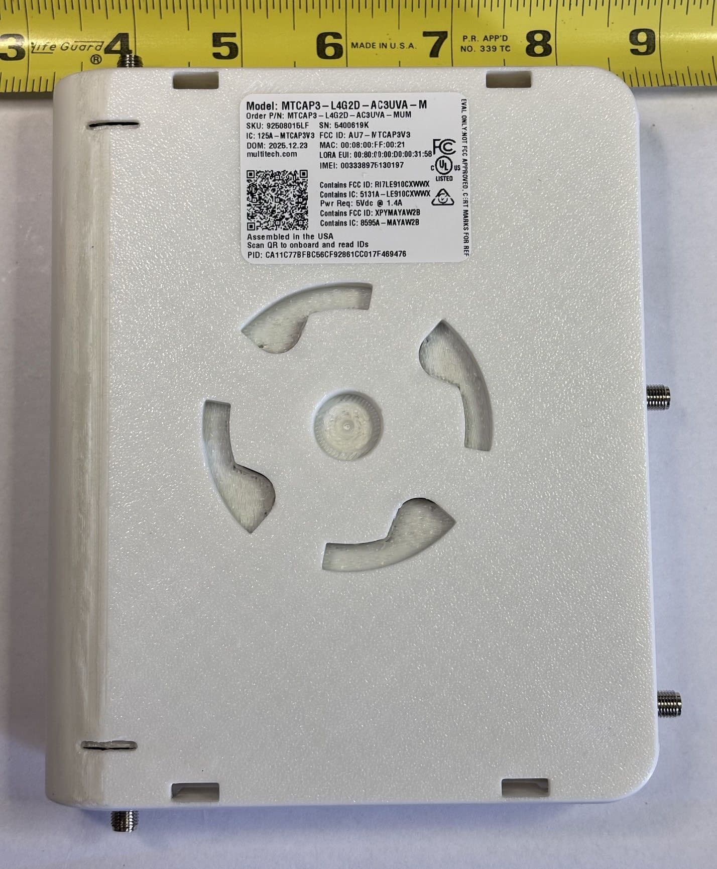
AU7-MTCAP3V3
Jun 17, 2026MTCAP3-L4G2D-AC3UVA-M, MTCAP3-L4G2D-AC3UWA-M
Equipment Class
DTS - Digital Transmission System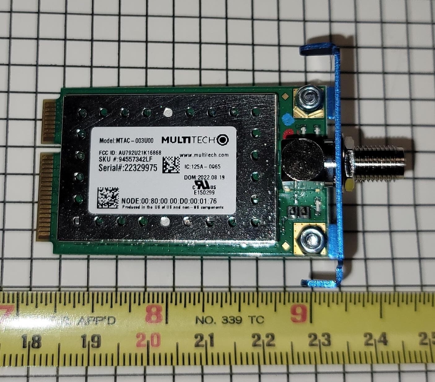
AU792U21K16868
Sep 24, 2023MTAC-003U00
Equipment Class
DTS - Digital Transmission System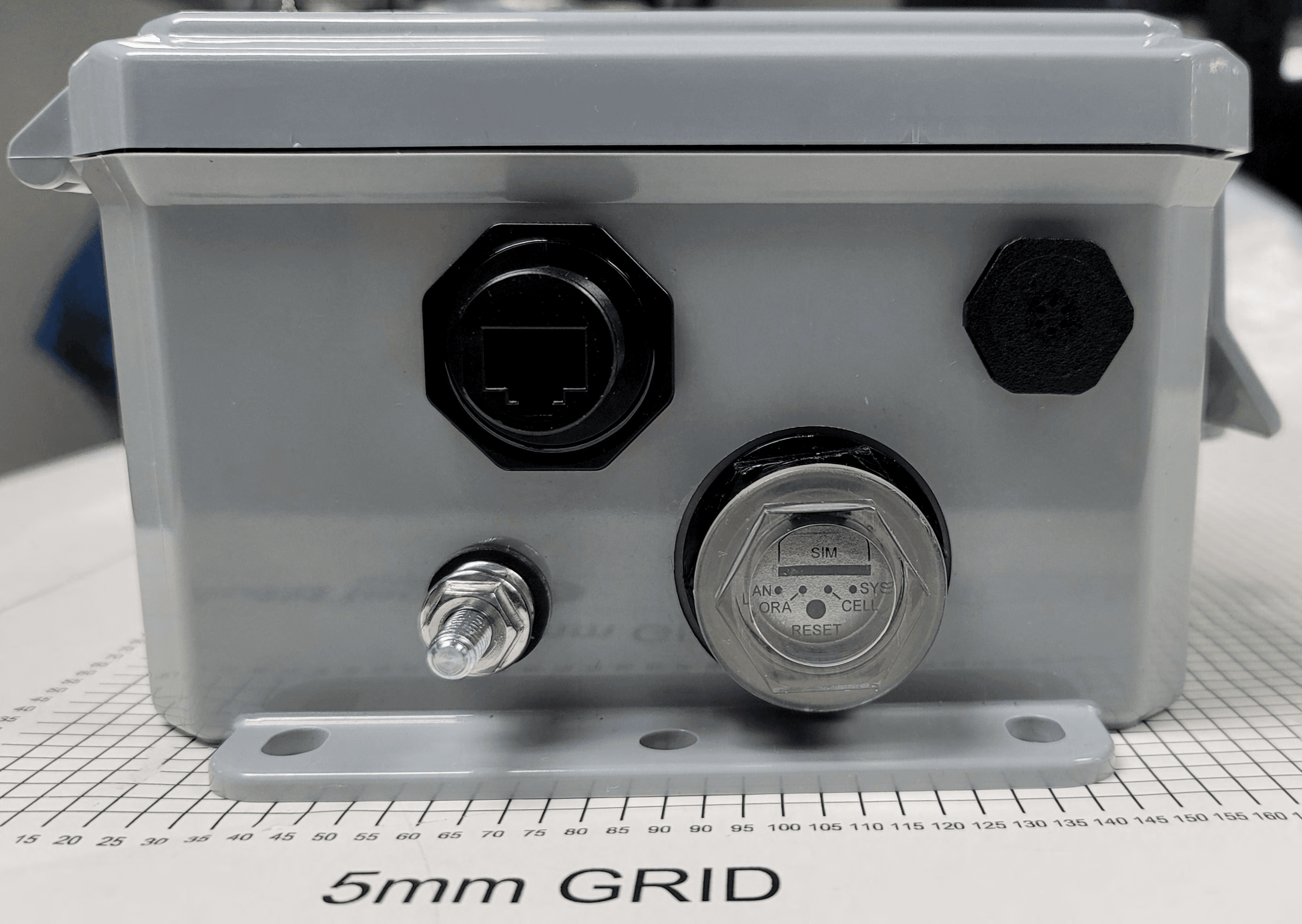
AU792U21B10865
Oct 04, 2021MTCDTIP2
Equipment Class
DTS - Digital Transmission System
AU792U19K19864
Mar 03, 2020MTCAP2-915
Equipment Class
DTS - Digital Transmission System
AU792U13A16856
Apr 26, 2015MTAC-Lora-915
Equipment Class
DTS - Digital Transmission System