AU792U10E068322G3G multiband modem (Socket Modem iCell)
Multi Tech Systems Inc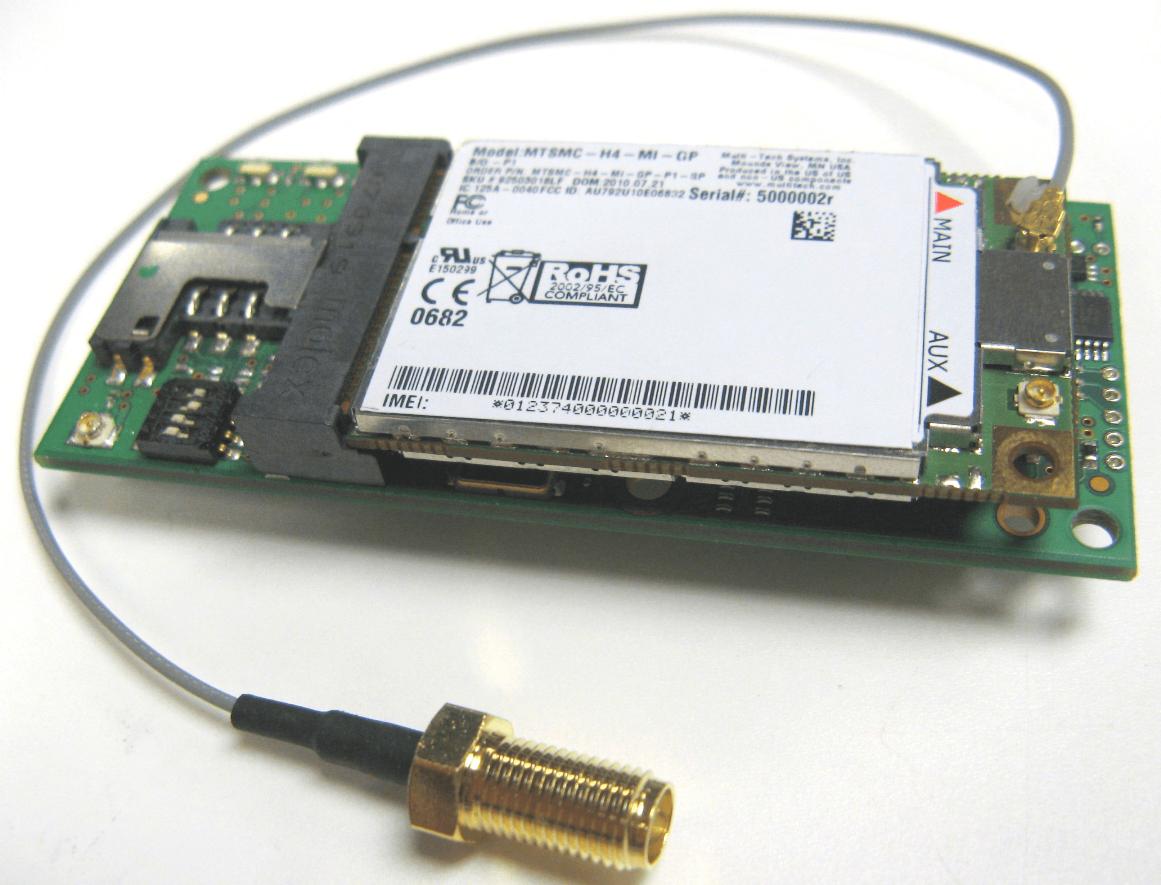
Click to zoom
Application Details
- Equipment Class
- PCB - PCS Licensed Transmitter
- Date of Grant
- Aug 25, 2010
- Application Purpose
- Original Equipment
- Date of Application
- Aug 25, 2010
- Equipment Note
- 2G3G multiband modem (Socket Modem iCell)
- Frequency Range
- 1852.40000000 - 1907.60000000
- Company
- Multi Tech Systems Inc
- Country
- United States
Documents & Files
Document Text
Text extracted from the exhibit documents filed with the FCC. Open a document above to read the original.
Users Manual
Universal Socket Connectivity Embedded Device Networking Solutions Hardware Guide for Developers Copyright and Technical Support Multi-Tech Systems, Inc. Universal Socket Hardware Guide for Developers (S000342M) 2 Universal Socket Connectivity Hardware Guide for Developers, PN S000342M, Version M For the following products (The list indicates base models for each product. See each product chapter product build options): Cellular SocketModems SocketModem® Cell – GPRS (MTSMC-G2, MTSMC-G2-V) SocketModem® iCell – GPRS (MTSMC-G2-IP, MTSMC-G2-GP) SocketModem® Cell – CDMA 1xRTT (MTSMC-C1, MTSMC-C1-V) SocketModem® iCell – CDMA 1xRTT (MTSMC-C1-IP, MTSMC-C1-GP) SocketModem® EDGE – (MTSMC-E1 and other build options) Socket Modem® Cell – HSPA (MTSMC-H4 – USB) Socket Modem® iCell – HSPA (MTSMC-H4 – IP and GP build options) Socket Modem® Cell – EV-DO (MTSMC-EV2 – USB) Socket Modem® iCell – EV-DO (MTSMC-EV2 – IP and GP build options) Analog SocketModems SocketModem® – MT9234SMI and other build options SocketModem® – MT5692SMI and other build options SocketModem® – MT2492SMI and other build options Embedded Device Servers SocketModem IP® – MT100SEM-IP and other build options SocketWireless® Wi-Fi® – MT810SWM-IP and other build options SocketWireless® Bluetooth® – MTS2BTSMI and other build options Copyright This publication may not be reproduced, in whole or in part, without prior expressed written permission from Multi-Tech Systems, Inc. All rights reserved. Copyright © 2004-10 by Multi-Tech Systems, Inc. Multi-Tech Systems, Inc. makes no representations or warranties with respect to the contents hereof and specifically disclaim any implied warranties of merchantability or fitness for any particular purpose. Furthermore, Multi-Tech Systems, Inc. reserves the right to revise this publication and to make changes from time to time in the content hereof without obligation of Multi-Tech Systems, Inc. to notify any person or organization of such revisions or changes. Trademarks Trademarks and Registered Trademarks of Multi-Tech Systems, Inc. are SocketModem, SocketWireless, SocketEthernet IP, and the Multi-Tech logo. Microsoft and Windows are trademarks or registered trademarks of Microsoft Corporation in the United States and other countries. Bluetooth is a registered trademark of the Bluetooth SIG, Inc. Wi-Fi is a registered trademark of the Wi-Fi Alliance. Contacting Multi-Tech Support Multi-Tech Online Support Portal https://support.multitech.com In order to better serve our customers, manage support requests and shorten resolution times, we have created the online web portal allowing you to submit questions regarding Multi-Tech products directly to our technical support team. Get answers to your most complex questions, ranging from implementation, troubleshooting, product configuration, firmware upgrades and much more. To create an account and submit a Support Case on the Portal, visit https://support.multitech.com Knowledge Base and Support Services: https://www.multitech.com/support.go The Knowledge Base provides immediate answers to your questions and gives you access to support resolutions for all Multi-Tech products. Visit our support area on the website for other support services. Technical Support Country By Email By Phone Europe, Middle East, Africa: [email protected] +(44) 118 959 7774 U.S., Canada, all others: [email protected] (800) 972-2439 or (763) 717-5863 Warranty Warranty information can found at: http://www.multitech.com/warranty.go World Headquarters Multi-Tech Systems, Inc. 2205 Woodale Drive Mounds View, Minnesota 55112 Phone: 763-785-3500 or 800-328-9717; Fax: 763-785-9874 Internet Address: http://www.multitech.com Revision Notes Multi-Tech Systems, Inc. Universal Socket Hardware Guide for Developers (S000342M) 3 Revision Notes Rev. Date Description J.2 07/30/09 • Updated Mechanical Drawings for SocketModem Cell & iCell (MTSMC-G2 & G2-IP) • Changed the title of two Mechanical Drawings in Chapter 1 J.3 08/28/09 • Updated Mechanical Drawings for SocketModem GPRS (MTSMC-G2) • Added new Mechanical Drawings for SocketModem CDMA ( MTSMC-C) & HSDPA MTSMC-H J.4 10/15/09 • Added GPS section to G2 chapter (added the power draw table for G2 for GPS) • Brought back the chapter covering the SocketModem MT2456SMI-22. K 11/18/09 • New chapters for new products: SocketModem MT5692SMI, Device Server MT810SWM-IP, and SocketModem EDGE (MTSMC-E1) • Deleted chapters SocketModem MT5656SMI, MT5656SMI-IP, and MT2456SMI-22 • Added Sleep Mode Power Draw statistics for the SocketModem MT9234SMI • Added new Mechanical Drawings for SocketModem HSDPA and SocketModem CDMA • Updated the Power Requirements for the MT2492SMI and MT5692SMI (10/16/09) • Added GPS to SocketModem Cell/SocketModem iCell (MTSMC-G2) and GPS power draw • Reorganized Chapter 1 – general information, cellular information, and analog information. • Added Japan's Standards statement • Updated Mechanical Drawings in Chapter 1 • New Developer Board Block Diagram with antenna system added L 03/12/10 • Added new CDMA-C1 chapter (replaces CDMA chapter) • Added Multi-Tech Technical Support using the Web Portal (see Copyright & Tech Support page) • Updated Universal Developer Kit contents • Added CDMA Specifications in Chapter 1 • Added Mag Mount Dual Band antennas and GPS antennas available from Multi-Tech • Added Mechanical Drawings: MT9234SMI, MT5692SMI, MT2492SMI, MT100SEM-IP, Bluetooth • Updated G2-GP power draw statistics • Updated the LED Interface Signals for G2 • Removed Loopback test references from MT9234SMI and MT5692SMI chapters • Added Important note about Tooling Holes and Mounting Hardware • Moved the CDMA Terminology and Acronyms chapter the CDMA AT Commands manual • Moved the GPS section into Chapter 1 • Removed "Features" from Technical Specifications • Enhanced the Antenna Section in Chapter 1 • Updated Bluetooth power draw statistics L.1 03/19/10 Changed three C1 Mechanical Drawings (-V, -IP, -GP) 04/15/10 Added a note in…
Text truncated - open the document above for the full version.
Cover Letter(s)
2205 Woodale Drive, Mounds View MN. 55112 www.multitech.com 1(2) © 2010 Multi-Tech Systems, Inc. Confidential Information of Multi-Tech Systems, Inc. Use Only Pursuant to Confidentiality Agreement with Multi-Tech Systems, Inc. Attention: Application Examiner Re: Request for confidentiality Applicant: Multi-Tech Systems, Inc. FCC ID: AU792U10E06832 To whom it may concern, Permanent Confidentiality Request is hereby submitted by Multi-Tech Systems, Inc. to withhold permanently from public review certain portions of the application for equipment certification for the referenced FCC identifiers. This request for confidentiality is made pursuant to 47 CFR 0.457(d) and 0.459 of the FCC Rules. In particular, the following sections of the application are to be kept permanently confidential: • Schematics • Detailed Block diagrams • Tune up procedure • Parts list Short-term Confidentiality Request is hereby submitted by Multi-Tech Systems, Inc. to withhold from public review for a period of 45 days from the date of the Grant of Equipment Authorization and prior to marketing, certain portions of the application for equipment certification for the referenced FCC identifiers. This request for confidentiality is made pursuant to 47 CFR 0.457(d) and 0.459 of the FCC Rules. In particular, the following sections of the application are to be kept confidential for a period of 45 days from the date of Authorization: • Detailed Operational/Functional Description • External photos • Internal photos • User manual 2205 Woodale Drive, Mounds View MN. 55112 www.multitech.com 2(2) © 2010 Multi-Tech Systems, Inc. Confidential Information of Multi-Tech Systems, Inc. Use Only Pursuant to Confidentiality Agreement with Multi-Tech Systems, Inc. Rationale for request for confidentiality: Multi-Tech Systems, Inc. has invested considerable time and materials in research and development to produce the referenced product. [Permanent confidentiality: Disclosure of the permanently confidential portions of this application to competitors would not only give them significant competitive advantages in developing similar products, but would also disclose successful implementation of unpublished, leading edge technology developed by us.][Short term confidentiality: Disclosure of the short-term confidential portions of this application during the period of importation and/or distribution would reveal key aspects of proprietary technology to competitors and diminish the value of our investment in research and development.] If you have questions or need further information, please contact the undersigned. Sincerely, Thomas Hofstede Compliance / Applications Engineer CTIA M2M SG Chairman Multi-Tech Systems, Inc. Direct: 763.717.5505 Mobile: 612.644.9242 www.multitech.com Multi-Tech Systems, Inc. 2205 Woodale Drive Mounds View, MN 55112
Cover Letter(s)
2205 Woodale Drive, Mounds View MN. 55112 www.multitech.com July 30, 2010 Declaration of Model Differences Dear examiner, We the undersigned declare that the model MTSMC-H4-MI-GP, MTSMC-H4-MI-IP, MTSMC-H4-GP, MTSMC-H4-IP and MTSMC-H4-U have identical RF radio circuitry. The MTSMC-H4-MI-GP is the base model and represents the MTSMC-H4 product family as the fully loaded model with all the functionality of each device in the product family. The below table shows the model, functionality and comment of change as it would compare to the MTSMC-H4-MI-GP the base or parent model. Model Functionality Comment of change MTSMC-H4-MI-GP HSPA, Serial and USB interface, GPIO, IP Stack and GPS Base or Parent model MTSMC-H4-MI-IP HSPA, Serial and USB interface, GPIO and IP Stack. 1. The GPS module is not integrated. MTSMC-H4-GP HSPA, Serial interface, IP Stack and GPS 1. No USB interface. 2. GPIO interface pins are removed. MTSMC-H4-IP HSPA, Serial interface, IP Stack 1. No USB interface. 2. GPIO interface pins are removed. 3. The GPS module is not integrated. MTSMC-H4-U HSPA and USB interface 1. No Serial interface. 2. GPIO interface pins are removed. 3. IP stack is not integrated.. 4. The GPS module is not integrated. 2205 Woodale Drive, Mounds View MN. 55112 www.multitech.com Any questions contact: Thomas Hofstede [email protected] Multi-Tech Systems, Inc. 2205 Woodale Drive Mounds View, MN 55112 Or Terry Boe [email protected] Multi-Tech Systems, Inc. 2205 Woodale Drive Mounds View, MN 55112 Sincerely, Thomas Hofstede Compliance Application Engineer
Operational Description
Universal Socket Connectivity Embedded Device Networking Solutions Hardware Guide for Developers Copyright and Technical Support Multi-Tech Systems, Inc. Universal Socket Hardware Guide for Developers (S000342M) 2 Universal Socket Connectivity Hardware Guide for Developers, PN S000342M, Version M For the following products (The list indicates base models for each product. See each product chapter product build options): Cellular SocketModems SocketModem® Cell – GPRS (MTSMC-G2, MTSMC-G2-V) SocketModem® iCell – GPRS (MTSMC-G2-IP, MTSMC-G2-GP) SocketModem® Cell – CDMA 1xRTT (MTSMC-C1, MTSMC-C1-V) SocketModem® iCell – CDMA 1xRTT (MTSMC-C1-IP, MTSMC-C1-GP) SocketModem® EDGE – (MTSMC-E1 and other build options) Socket Modem® Cell – HSPA (MTSMC-H4 – USB) Socket Modem® iCell – HSPA (MTSMC-H4 – IP and GP build options) Socket Modem® Cell – EV-DO (MTSMC-EV2 – USB) Socket Modem® iCell – EV-DO (MTSMC-EV2 – IP and GP build options) Analog SocketModems SocketModem® – MT9234SMI and other build options SocketModem® – MT5692SMI and other build options SocketModem® – MT2492SMI and other build options Embedded Device Servers SocketModem IP® – MT100SEM-IP and other build options SocketWireless® Wi-Fi® – MT810SWM-IP and other build options SocketWireless® Bluetooth® – MTS2BTSMI and other build options Copyright This publication may not be reproduced, in whole or in part, without prior expressed written permission from Multi-Tech Systems, Inc. All rights reserved. Copyright © 2004-10 by Multi-Tech Systems, Inc. Multi-Tech Systems, Inc. makes no representations or warranties with respect to the contents hereof and specifically disclaim any implied warranties of merchantability or fitness for any particular purpose. Furthermore, Multi-Tech Systems, Inc. reserves the right to revise this publication and to make changes from time to time in the content hereof without obligation of Multi-Tech Systems, Inc. to notify any person or organization of such revisions or changes. Trademarks Trademarks and Registered Trademarks of Multi-Tech Systems, Inc. are SocketModem, SocketWireless, SocketEthernet IP, and the Multi-Tech logo. Microsoft and Windows are trademarks or registered trademarks of Microsoft Corporation in the United States and other countries. Bluetooth is a registered trademark of the Bluetooth SIG, Inc. Wi-Fi is a registered trademark of the Wi-Fi Alliance. Contacting Multi-Tech Support Multi-Tech Online Support Portal https://support.multitech.com In order to better serve our customers, manage support requests and shorten resolution times, we have created the online web portal allowing you to submit questions regarding Multi-Tech products directly to our technical support team. Get answers to your most complex questions, ranging from implementation, troubleshooting, product configuration, firmware upgrades and much more. To create an account and submit a Support Case on the Portal, visit https://support.multitech.com Knowledge Base and Support Services: https://www.multitech.com/support.go The Knowledge Base provides immediate answers to your questions and gives you access to support resolutions for all Multi-Tech products. Visit our support area on the website for other support services. Technical Support Country By Email By Phone Europe, Middle East, Africa: [email protected] +(44) 118 959 7774 U.S., Canada, all others: [email protected] (800) 972-2439 or (763) 717-5863 Warranty Warranty information can found at: http://www.multitech.com/warranty.go World Headquarters Multi-Tech Systems, Inc. 2205 Woodale Drive Mounds View, Minnesota 55112 Phone: 763-785-3500 or 800-328-9717; Fax: 763-785-9874 Internet Address: http://www.multitech.com Revision Notes Multi-Tech Systems, Inc. Universal Socket Hardware Guide for Developers (S000342M) 3 Revision Notes Rev. Date Description J.2 07/30/09 • Updated Mechanical Drawings for SocketModem Cell & iCell (MTSMC-G2 & G2-IP) • Changed the title of two Mechanical Drawings in Chapter 1 J.3 08/28/09 • Updated Mechanical Drawings for SocketModem GPRS (MTSMC-G2) • Added new Mechanical Drawings for SocketModem CDMA ( MTSMC-C) & HSDPA MTSMC-H J.4 10/15/09 • Added GPS section to G2 chapter (added the power draw table for G2 for GPS) • Brought back the chapter covering the SocketModem MT2456SMI-22. K 11/18/09 • New chapters for new products: SocketModem MT5692SMI, Device Server MT810SWM-IP, and SocketModem EDGE (MTSMC-E1) • Deleted chapters SocketModem MT5656SMI, MT5656SMI-IP, and MT2456SMI-22 • Added Sleep Mode Power Draw statistics for the SocketModem MT9234SMI • Added new Mechanical Drawings for SocketModem HSDPA and SocketModem CDMA • Updated the Power Requirements for the MT2492SMI and MT5692SMI (10/16/09) • Added GPS to SocketModem Cell/SocketModem iCell (MTSMC-G2) and GPS power draw • Reorganized Chapter 1 – general information, cellular information, and analog information. • Added Japan's Standards statement • Updated Mechanical Drawings in Chapter 1 • New Developer Board Block Diagram with antenna system added L 03/12/10 • Added new CDMA-C1 chapter (replaces CDMA chapter) • Added Multi-Tech Technical Support using the Web Portal (see Copyright & Tech Support page) • Updated Universal Developer Kit contents • Added CDMA Specifications in Chapter 1 • Added Mag Mount Dual Band antennas and GPS antennas available from Multi-Tech • Added Mechanical Drawings: MT9234SMI, MT5692SMI, MT2492SMI, MT100SEM-IP, Bluetooth • Updated G2-GP power draw statistics • Updated the LED Interface Signals for G2 • Removed Loopback test references from MT9234SMI and MT5692SMI chapters • Added Important note about Tooling Holes and Mounting Hardware • Moved the CDMA Terminology and Acronyms chapter the CDMA AT Commands manual • Moved the GPS section into Chapter 1 • Removed "Features" from Technical Specifications • Enhanced the Antenna Section in Chapter 1 • Updated Bluetooth power draw statistics L.1 03/19/10 Changed three C1 Mechanical Drawings (-V, -IP, -GP) 04/15/10 Added a note in…
Text truncated - open the document above for the full version.
RF Exposure Info
Evaluation of RF Exposure for MC8790 Wireless Modem as a Mobile Device In this application we seek modular approval to the MC8790 wireless modem for use in mobile configuration. Based on the FCC OET Bulletin 65 Supplement C and 47 CFR §2.1091, we have concluded that the MC8790 will comply with the FCC rules on RF exposure for mobile devices if the antenna gain does not exceed 5 dBi in cellular band and 4 dBi in PCS band. The following analysis will demonstrate such compliance. The analysis will be done in two US bands. Operation in cellular band (824 – 849 MHz) The peak conducted output power of MC8790 in Cellular band is 32 dBm. Take the worst case as an example, in which an antenna with 5 dBi gain is used. The resulted power density at a distance of 20 cm can be deducted as follows: EIRP = 32 + 5 = 37 dBm = 5012 mW Power Density = EIRP*DutyCycle/(4 πR 2 ) = 5012*0.5/(4*π*20 2 ) = 0.50 mW/cm 2 where DutyCycle is 0.5 for GPRS operation (the worst case) and R is 20 cm. The MPE limit for General Population/Uncontrolled Exposure is shown in the FCC OET Bulletin 65 Supplement C and can be calculated as follows: MPE limit = 824/1500 = 0.55 mW/cm 2 As we can see the resulted power density is below the MPE limit, therefore MC8790 in Cellular band is compliant with the FCC rules on RF exposure. Operation in PCS band (1850 – 1910 MHz) The peak conducted output power of MC8790 in PCS band is 29 dBm. Take the worst case as an example, in which an antenna with 4 dBi gain is used. The resulted ERP can be expressed as follows: ERP = 29 + 4 –2.15 = 30.85 dBm (1.22 W) < 3 W The FCC OET Bulletin 65 Supplement C states that mobile devices identified in 47 CFR §2.1091 that operate at frequencies above 1.5 GHz with an ERP of 3.0 watts or more are required to perform routine environmental evaluation for RF exposure prior to equipment authorization or use; otherwise, they are categorically excluded. As we can see this resulted ERP is below 3 W, therefore routine environmental evaluation for RF exposure prior to equipment authorization or use for MC8790 in PCS band is categorically excluded.
Test Report
Bluetooth Qualification Test Facility (BQTF) FCC listed: A2LA Accredited IC recognized # 3462B-1 CETECOM Inc. 411 Dixon Landing Road Milpitas, CA 95035 U.S.A. Phone: + 1 (408) 586 6200 Fax: + 1 (408) 586 6299 E-mail: [email protected] http://www.cetecom.com CETECOM Inc. is a Delaware Corporation with Corporation number: 2113686 Board of Directors: Dr. Harald Ansorge, Hans Peter May. Gerhard Schirra V2.0 2009-10-30 The BLUETOOTH trademarks are owned by Bluetooth SIG, Inc., U.S.A. and licensed to CETECOM Inc. © Copyright by CETECOM FCC/IC Test Report FOR: Model Name: MTSMC-H4-MI-GP, MTSMC-H4-MI-IP, MTSMC-H4-GP, MTSMC-H4-IP, MTSMC-H4-U Socket Modem iCell FCC ID: AU792U10E06832 IC ID: 125A-0040 47 CFR Part 2, 22, 24 RSS-132 Issue 2 RSS-133 Issue 5 TEST REPORT #: EMC_Multi_045_10001_FCC_22_24_Rev1 DATE: 2010-08-23 Test Report #: EMC_Multi_045_10001 _FCC22_24_Rev1 Date of Report: 2010-08-23 Page 2 of 59 Table of Contents 1 Assessment .............................................................................................................................. 3 2 Administrative Data ............................................................................................................... 4 2.1 Identification of the Testing Laboratory Issuing the EMC Test Report ......................................... 4 2.2 Identification of the Client ............................................................................................................. 4 2.3 Identification of the Manufacturer ................................................................................................. 4 3 Equipment under Test (EUT) ............................................................................................... 5 3.1 Specification of the Equipment under Test .................................................................................... 5 3.2 Identification of the Equipment Under Test (EUT) ....................................................................... 6 3.3 Identification of Accessory equipment........................................................................................... 6 4 Subject of Investigation ......................................................................................................... 7 5 Measurements ......................................................................................................................... 8 5.1 RF Power Output ............................................................................................................................ 8 5.1.1 References .............................................................................................................................. 8 5.1.2 Measurement requirements: ................................................................................................... 8 5.1.3 Limits: .................................................................................................................................... 8 5.1.4 Test Results: ........................................................................................................................... 8 5.1.5 Radiated Output Power Measurement procedure .................................................................. 9 5.1.6 RF Power Output 850MHz band .......................................................................................... 10 5.1.7 RF Power Output 1900MHz band ........................................................................................ 11 5.1.8 Results .................................................................................................................................. 12 5.2 Occupied Bandwidth/Emission Bandwidth .................................................................................. 24 5.2.1 References ............................................................................................................................ 24 5.2.2 Measurement requirements: ................................................................................................. 24 5.2.3 Test Results: ......................................................................................................................... 24 5.3 Frequency Stability ...................................................................................................................... 25 5.3.1 References ............................................................................................................................ 25 5.3.2 Measurement requirements: ................................................................................................. 25 5.3.3 Test Results: ......................................................................................................................... 25 5.4 Conducted Spurious Emissions .................................................................................................... 26 5.4.1 References ............................................................................................................................ 26 5.4.2 Measurement requirements: ................................................................................................. 26 5.4.3 Test Results: ......................................................................................................................... 26 5.5 Spurious Emissions Radiated ....................................................................................................... 27 5.5.1 References ............................................................................................................................ 27 5.5.2 Measurement requirements: ................................................................................................. 27 5.5.3 Limits: .................................................................................................................................. 27 5.5.4 Radiated out of band measurement procedure: .............................................…
Text truncated - open the document above for the full version.
Test Report
2008 Sierra Wireless, Inc. This document contains information which is proprietary and confidential to Sierra Wireless, Inc. Disclosure to persons other than the officers, employees, agents, or subcontractors of the Company or licensee of this document without the prior written permission of Sierra Wireless, Inc. is strictly prohibited. MC8790 Test Report FCC Part 22, 24 / IC RSS 132, 133 FOR FCC and IC Certifications IC: 2417C-MC8790 FCC ID: N7NMC8790 Prepared by SIERRA WIRELESS INC. 13811 WIRELESS WAY RICHMOND, BC V6V 3A4 CANADA SIERRA WIRELESS, INC. FCC Part 22, 24 / RSS 132, 133 MC8790 Dec 1, 2008 Page 2 of 77 2008 Sierra Wireless, Inc. The contents of this page are subject to the confidentiality information on page one. Table of Contents 1 Introduction and Purpose....................................................................... 3 2 Test Summary ....................................................................................... 3 3 Description of Equipment Under Test ................................................... 4 4 RF Power Output .................................................................................. 4 4.1 Test Procedure .................................................................................................... 4 4.2 Test Equipment.................................................................................................... 5 4.3 Test Results GSM/EDGE .................................................................................... 5 4.4 Test Results UMTS .............................................................................................. 5 4.4.1 Test 1: RF Output Power Results for WCDMA R99................................... 5 4.4.2 Test 2: RF Output Power Results for HSDPA Rel6.................................... 6 4.4.3 Test 3: RF Output Power Results for HSPA (HSDPA & HSUPA) Rel6..... 8 4.5 Test Settings for UMTS Mode on CMU200 ...................................................... 10 5 Occupied Bandwidth ........................................................................... 14 5.1 Test Procedure .................................................................................................. 14 5.2 Test Results ....................................................................................................... 14 5.3 Test Plots........................................................................................................... 15 6 Out of Band Emissions at Antenna Terminals ..................................... 24 6.1 Test Procedure .................................................................................................. 24 6.2 Test Equipment.................................................................................................. 24 6.3 Test Results ....................................................................................................... 25 6.4 Test Plots........................................................................................................... 26 7 Block Edge Compliance...................................................................... 62 7.1 Test Procedure .................................................................................................. 62 7.2 Test Equipment.................................................................................................. 62 7.3 Test Results ....................................................................................................... 62 7.4 Test Plots........................................................................................................... 63 8 Frequency Stability Versus Temperature............................................. 69 8.1 Summary of Results........................................................................................... 69 8.2 Test Procedure .................................................................................................. 69 8.3 Test Equipment.................................................................................................. 69 8.4 Test Results ....................................................................................................... 70 9 Frequency Stability Versus Voltage .................................................... 74 9.1 Summary of Results........................................................................................... 74 9.2 Test Procedure .................................................................................................. 74 9.3 Test Equipment.................................................................................................. 74 9.4 Test Results ....................................................................................................... 75 SIERRA WIRELESS, INC. FCC Part 22, 24 / RSS 132, 133 MC8790 Dec 1, 2008 Page 3 of 77 2008 Sierra Wireless, Inc. The contents of this page are subject to the confidentiality information on page one. 1 Introduction and Purpose This document provides the MC8790 wireless modem test data for the FCC and Industry Canada certifications. The tests included in this report are limited to all conducted tests required. The radiated tests were performed at an external test facility. 2 Test Summary FCC RULE IC Standards DESCRIPTION OF TEST RESULT PAGE 2.1046 RSS-132, 4.4 RSS-133, 6.4 RF Power Output Complies 5 2.1049 RSS-Gen, 4.6 Occupied Bandwidth Complies 14 2.1051 22.901(d) 22.917 24.238(a) RSS-132, 4.5 RSS-133, 6.5 Out o…
Text truncated - open the document above for the full version.
Contact Information
Applicant
Tim Gunn(Director of Certifications and Product Support)
Technical Contact
Multi Tech Systems Inc.Thomas Hofstede
2205 Woodale Drive · Mounds View · United States
Test Firm
CETECOM Inc.Meinolf Glunz
[email protected]408-586-6301
Technical Specifications
| # | Rule Parts | Frequency Range | Power Output | Emission | Tolerance |
|---|---|---|---|---|---|
| 6 | 24E | 1.85 GHz - 1.91 GHz | 851.00 mW | 4M59F9W | 0.0064 ppm |
Other Applications from Multi Tech Systems Inc
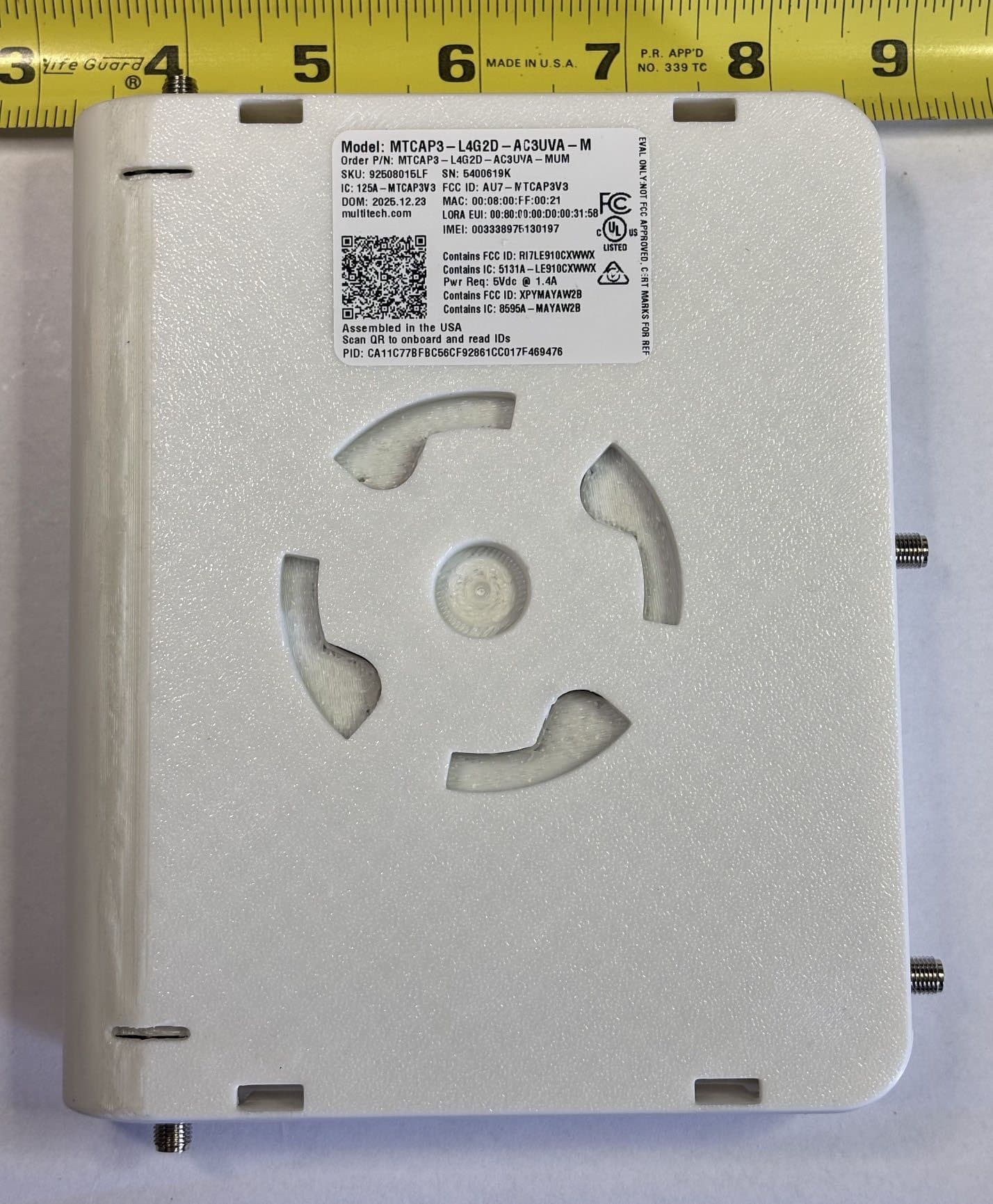
AU7-MTCAP3V3
Jun 17, 2026MTCAP3-L4G2D-AC3UVA-M, MTCAP3-L4G2D-AC3UWA-M
Equipment Class
DTS - Digital Transmission System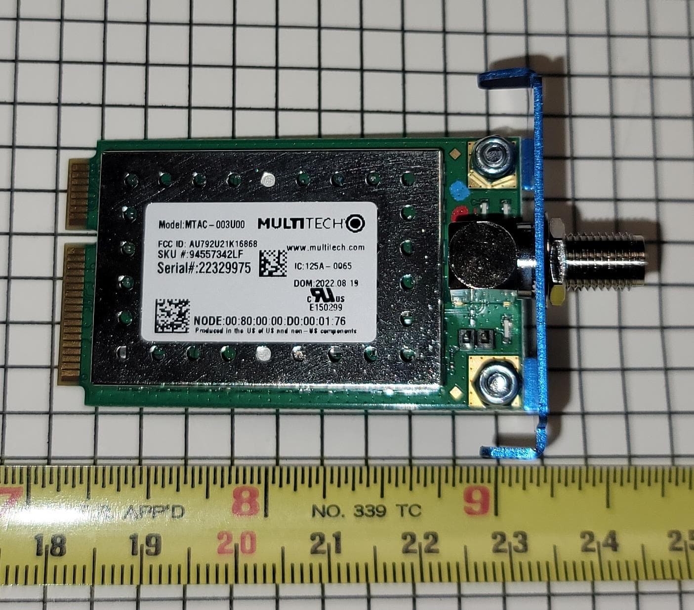
AU792U21K16868
Sep 24, 2023MTAC-003U00
Equipment Class
DTS - Digital Transmission System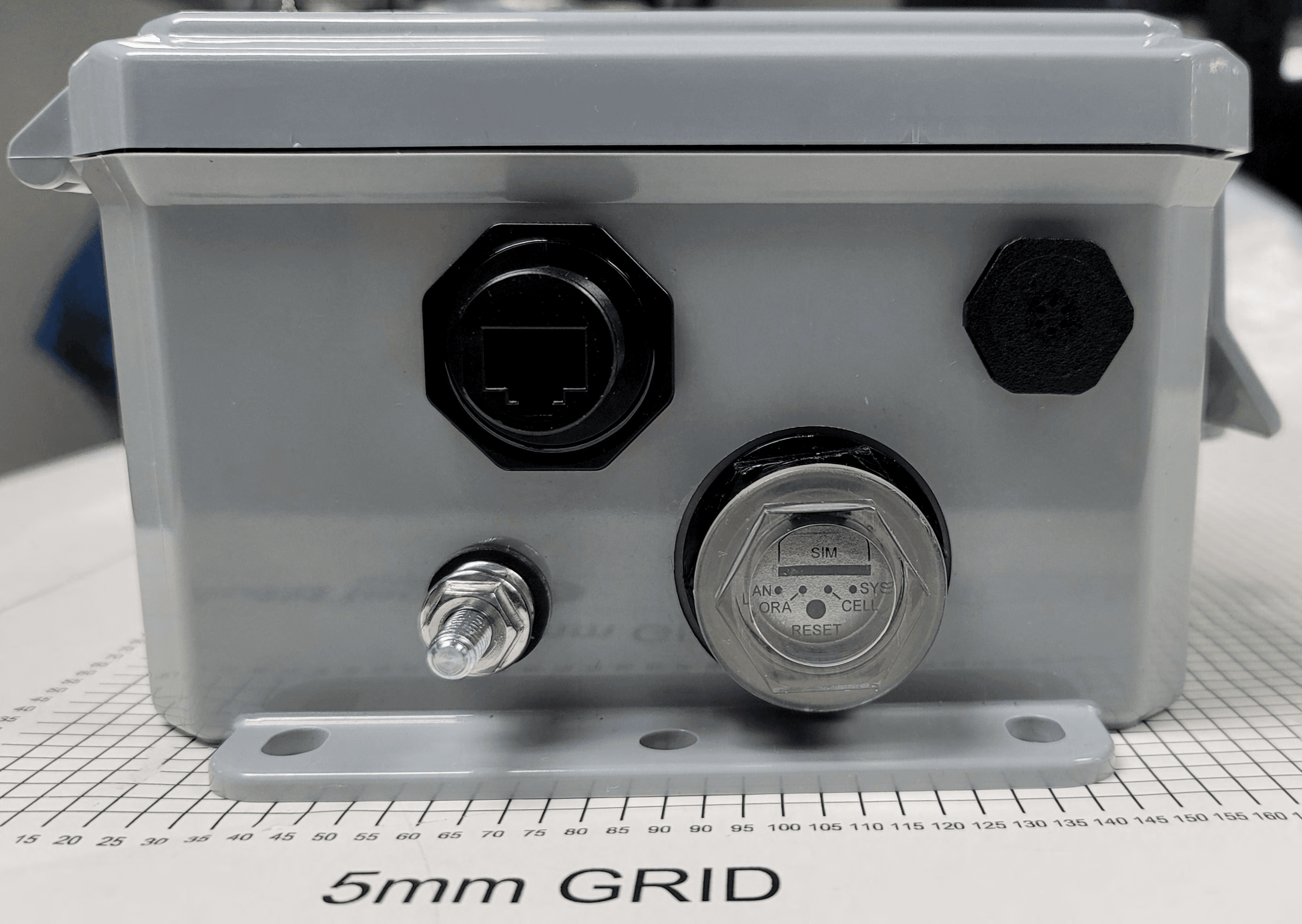
AU792U21B10865
Oct 04, 2021MTCDTIP2
Equipment Class
DTS - Digital Transmission System
AU792U19K19864
Mar 03, 2020MTCAP2-915
Equipment Class
DTS - Digital Transmission System
AU792U13A16856
Apr 26, 2015MTAC-Lora-915
Equipment Class
DTS - Digital Transmission System