AUBWSELFTSmoke Detector, Self-Test Capable
Honeywell International Inc.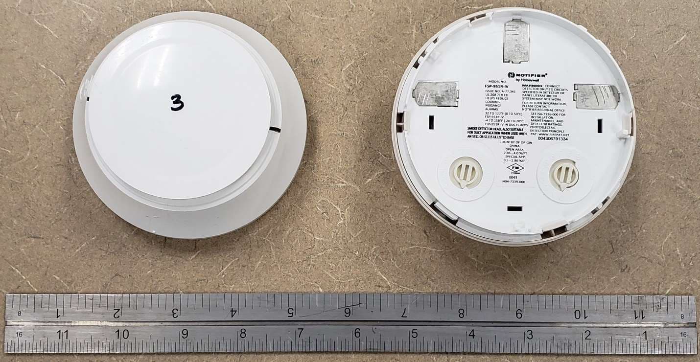
Click to zoom
Application Details
- Equipment Class
- DTS - Digital Transmission System
- Date of Grant
- Jan 23, 2021
- Application Purpose
- Original Equipment
- Date of Application
- Jan 23, 2021
- Equipment Note
- Smoke Detector, Self-Test Capable
- Frequency Range
- 2402.00000000 - 2480.00000000
- Company
- Honeywell International Inc.
- Country
- United States
Documents & Files
Document Text
Text extracted from the exhibit documents filed with the FCC. Open a document above to read the original.
Users Manual
should be placed more than 3ft (914mm) away from any strong air source which is greater than 300 ft./min. (e.g. an air conditioning outlet). Duct Applications: FSP-951-SELFT is not listed for use in ducts. Mounting Note: Units installed on ceilings must remain in ceiling-oriented position; those mounted on walls must remain in the wall orientation. WIRING GUIDE All wiring must be installed in compliance with the National Electrical Code, applicable local codes, and any special requirements of the Authority Having Jurisdiction. Proper wire gauges should be used. The installation wires should be color-coded to limit wiring mistakes and ease system troubleshooting. Im- proper connections will prevent a system from responding properly in the event of a fire. Please note that installation distances, wiring styles and wire gauge requirements may vary for Self-Test sensors in comparison to standard sensors, please refer to the panel's SLC Wiring documentation for further in- formation. Remove power from the communication line before installing sensors. 1. Wire the sensor base (supplied separately) as shown in the wiring diagram. (See Figure 2.) 2. Set the desired address on the sensor address switches. (See Figure 1.) 3. Install the sensor into the sensor base. Push the sensor into the base while turning it clockwise to secure it in place. 4. After all sensors have been installed, apply power to the control panel and activate the communication line. 5. Test the sensor(s) as described in the TESTING section of this manual. CAUTION Dust covers provide limited protection against airborne dust particles during shipping. Dust covers must be removed before the sensors can sense smoke. Remove sensors prior to heavy remodeling or construction. The Self-Test func- tion of your Notifier system can determine that all dust covers on the SLC have been removed when you run the Self-Test process in order to prove that there isn’t anything causing a potential obstruction for smoke entry. SPECIFICATIONS Operating Voltage Range: 15 to 32 VDC Operating Current @ 24 VDC: 200 uA (one communication every 5 seconds with green LED blink on communication) Maximum Alarm Current: 2 mA @ 24 VDC (one communication every 5 seconds with red LED solid on) Maximum Self-Test Alarm Current: 300 mA (Not be used for battery standby calculation as Self-Test will not work in auxiliary power mode) Maximum Current: 4.5 mA @ 24 VDC (one communication every 5 seconds with amber LED solid on) Operating Humidity Range: 10% to 93% Relative Humidity, Non-condensing Operating Temperature Range: 32°F to 122°F (0°C to 50°C) Storage Temperature Range: -4°F to 140°F (-20°C to 60°C) Air Velocity: 0 to 4000 ft./min. (0 to 1219.2 m/min.) Air Velocity using Self-Test: 0 to 300 ft./min. (0 to 304.8 m/min.) Height: 2.0 ̋ (51 mm) installed in B300-6 Base Diameter: 6.2 ̋ (156 mm) installed in B300-6 Base; 4.1 ̋ (104 mm) installed in B501 Base Weight: 3.5 oz. (100 g) Isolator Load Rating: 0.0063* *Please refer to your isolator base/module manual for isolator calculation instructions. UL 268 listed for Open Air Protection. This sensor must be installed in compliance with the control panel system installation manual. The installation must meet the requirements of the Au- thority Having Jurisdiction (AHJ). Sensors offer maximum performance when installed in compliance with the National Fire Protection Association (NFPA); see NFPA 72. GENERAL DESCRIPTION Model FSP-951-SELFT is a plug-in type smoke sensor that combines a photo- electronic sensing chamber with addressable-analog communications. The sensor transmits an analog representation of smoke density over a com- munication line to a control panel. Rotary dial switches are provided for set- ting the sensor’s address. (See Figure 1.) FIGURE 1. ROTARY ADDRESS SWITCHES TENSONES 9 10 11 12 13 14 15 8 7 6 5 4 3 2 1 0 9 8 7 6 5 4 3 2 1 0 C0162-00 Two LEDs on the sensor are controlled by the panel to indicate sensor status. An output is provided for connection to an optional remote LED annunciator (P/N RA100Z). Notifier panels offer different features sets across different models. As a result, certain features of the photoelectric sensors may be available on some con- trol panels, but not on others. FSP-951-SELFT will support only FlashScan® protocol mode. The possible features available in the photoelectric sensors, if supported by the control panel are: 1. The sensor’s LEDs can operate in three ways—on, off, and blinking–and they can be set to red, green, or amber. This is controlled by the panel. 2. The remote output may be synchronized to the LED operation or con- trolled independent of the LEDs. 3. Devices are point addressable up to 159 addresses. 5. Yearly maintenance, in accordance to NFPA 72, can use the built in Self- Test functionality. Please refer to the operation manual for the UL listed control panel for specific operation. The photoelectric sensors require compatible addressable com- munications to function properly. Connect these sensors to listed-compatible control panels only. SPACING AND MOUNTING Notifier recommends spacing sensors in compliance with NFPA 72. In low air flow applications with smooth ceilings, space sensors 30 feet apart (9.1 m). For specific information regarding sensor spacing, placement, and special ap- plications, refer to NFPA 72 or the System Smoke Detector Application Guide, available from Notifier. If using the self-test application, the FSP-951-SELFT I56-6782-000 INSTALLATION AND MAINTENANCE INSTRUCTIONS 12 Clintonville Road Northford, CT 06472-1653 Phone: 203.484.7161 FSP-951-SELFT Intelligent Photoelectric Self-Test Smoke Sensor 1 I56-6782-000 1/6/2021 FIGURE 2. WIRING DIAGRAM 2 3 1 2 3 3 1 2 1 (–) (+) +- UL Listed Compatible Control Panel CAUTION: Do not loop wire under terminal 1 or 2. Break wire run to supervise connections. CLASS A OPTIONAL WIRING Remote Annunciator (–) (+) RA + – + RA + – + RA + – + C0129-10 TAMPER-RESISTANCE Intelligent photoelectric smoke sen…
Text truncated - open the document above for the full version.
Users Manual
SPACING & MOUNTING Notifier recommends spacing sensors in compliance with NFPA 72. In low air flow applications with smooth ceilings, space sensors 30 feet apart (9.1 m). When using the photoelectric and temperature sensors as a heat detector in FM3210 compliant applications, space sensors 20 feet apart (6 m). For specific informa- tion regarding sensor spacing, placement, and special applications, refer to NFPA 72 or the System Smoke Detector Application Guide, available from Notifier. Duct Applications: FSP-951T-SELFT is not listed for use in ducts. Mounting Note: Units installed on ceilings must remain in ceiling-oriented position; those mounted on walls must remain in the wall orientation. WIRING GUIDE All wiring must be installed in compliance with the National Electrical Code, applicable local codes, and any special requirements of the Authority Having Jurisdiction. Proper wire gauges should be used. The installation wires should be color-coded to limit wiring mistakes and ease system troubleshooting. Im- proper connections will prevent a system from responding properly in the event of a fire. Please note that installation distances, wiring styles and wire gauge requirements may vary for Self-Test sensors in comparison to standard sensors, please refer to the panel's SLC Wiring documentation for further in- formation. Remove power from the communication line before installing sensors. 1. Wire the sensor base (supplied separately) per the wiring diagram, Figure 2. 2. Set the desired address on the sensor address switches, see Figure 1. 3. Install the sensor into the sensor base. Push the sensor into the base while turning it clockwise to secure it in place. 4. After all sensors have been installed, apply power to the control panel and activate the communication line. 5. Test the sensor(s) as described in the TESTING section of this manual. CAUTION Dust covers provide limited protection against airborne dust particles during shipping. Dust covers must be removed before the sensors can sense smoke. Remove sensors prior to heavy remodeling or construction. The Self-Test func- tion of your Notifier system can determine that all dust covers on the SLC have been removed when you run the Self-Test process in order to prove that there isn’t anything causing a potential obstruction for smoke entry. SPECIFICATIONS Operating Voltage Range: 15 to 32 VDC Operating Current @ 24 VDC: 200 uA (one communication every 5 seconds with green LED blink on communication) Maximum Alarm Current: 2 mA @ 24 VDC (one communication every 5 seconds with red LED solid on) Maximum Self-Test Alarm Current: 300 mA (Not be used for battery standby calculation as Self-Test will not work in auxiliary power mode) Maximum Current: 4.5 mA @ 24 VDC (one communication every 5 seconds with amber LED solid on) Operating Humidity Range: 10% to 93% Relative Humidity, Non-condensing Operating Temperature Range: 32°F to 115°F (0°C to 47°C) Storage Temperature Range: -4°F to 140°F (-20°C to 60°C) Air Velocity: 0 to 4000 ft./min. (0 to 1219.2 m/min.) Air Velocity using Self-Test: 0 to 300 ft./min. (0 to 304.8 m/min.) Height: 2.0 ̋ (51 mm) installed in B300-6 Base Diameter: 6.2 ̋ (156 mm) installed in B300-6 Base; 4.1 ̋ (104 mm) installed in B501 Series Base Weight: 3.5 oz. (100 g) Isolator Load Rating: 0.0063* *Please refer to your isolator base/module manual for isolator calculation instructions. UL 268 listed for Open Air Protection UL 521 listed for Heat Detectors This sensor must be installed in compliance with the control panel system installation manual. The installation must meet the requirements of the Au- thority Having Jurisdiction (AHJ). Sensors offer maximum performance when installed in compliance with the National Fire Protection Association (NFPA); see NFPA 72. GENERAL DESCRIPTION Model FSP-951T-SELFT is a plug-in type multi-sensor smoke sensor that com- bines a photoelectronic sensing chamber and 135°F (57.2°C) fixed temper- ature heat detector across addressable-analog communications. The sensor transmits an analog representation of smoke density over a communication line to a control panel. Its internal Self-Test unit and beaconing capability can test the detector to relevant requirements of NFPA 72. Rotary dial switches are provided for setting the sensor’s address. (See Fig- ure 1.) The intelligent photoelectric and temperature sensors also transmit an alarm signal due to heat at 135°F (57.2°C) per UL 521. FIGURE 1. ROTARY ADDRESS SWITCHES TENSONES 9 10 11 12 13 14 15 8 7 6 5 4 3 2 1 0 9 8 7 6 5 4 3 2 1 0 C0162-00 Two LEDs on the sensor are controlled by the panel to indicate sensor status. An output is provided for connection to an optional remote LED annunciator (P/N RA100Z). Notifier panels offer different features sets across different models. As a result, certain features of the photoelectric and temperature sensors may be available on some control panels, but not on others. FSP-951T-SELFT will support only FlashScan® protocol mode. The possible features available if supported by the control panel are: 1. The sensor’s LEDs can operate in three ways—on, off, and blinking–and they can be set to red, green, or amber. This is controlled by the panel. 2. The remote output may be synchronized to the LED operation or con- trolled independent of the LEDs. 3. Devices are point addressable up to 159 addresses. 5. Yearly maintenance, in accordance to NFPA 72, can use the built in Self- Test functionality. Please refer to the operation manual for the UL listed control panel for spe- cific operation. The photoelectric and temperature sensors require compatible addressable communications to function properly. Connect these sensors to listed-compatible control panels only. I56-6783-000 INSTALLATION AND MAINTENANCE INSTRUCTIONS 12 Clintonville Road Northford, CT 06472-1653 Phone: 203.484.7161 FSP-951T-SELFT Intelligent Photoelectric and Temperature Self-Test Smoke Sensor 1 I56-6783-000 1/6/2021 FIGURE 2. WIRING DIAGRAM 2 3…
Text truncated - open the document above for the full version.
Users Manual
3. Devices are point addressable up to 159 addresses. 4. The heat sensor operates as a programmable heat detector. 5. Yearly maintenance, in accordance to NFPA 72, can use the built in Self- Test functionality. Intelligent programmable temperature sensors require compatible addressable communications to function properly. Connect these sensors to listed-compat- ible control panels only. WIRING GUIDE All wiring must be installed in compliance with the National Electrical Code, applicable local codes and the Authority Having Jurisdiction. Proper wire gauges should be used. The installation wires should be color coded to limit wiring mistakes and ease system troubleshooting. Improper connections will prevent a system from responding properly in the event of a fire. Please note that installation distances, wiring styles and wire gauge requirements may vary for Self-Test sensors in comparison to standard sensors, please refer to the panel's SLC Wiring documentation for further information. Remove power from the communication line before installing sensors. 1. Wire the sensor base (supplied separately) as shown in the wiring diagram. (See Figure 2.) 2. Set the desired address on the rotary dial switches. (See Figure 1.). 3. Install the sensor into the sensor base. Push the sensor into the base while turning it clockwise to secure it in place. 4. After all sensors have been installed, apply power to the control unit and activate the communication line. 5. Test the sensor(s) as described in the TESTING section of this manual. FIGURE 2. WIRING DIAGRAM 2 3 1 2 3 3 1 2 1 (–) (+) +- UL Listed Compatible Control Panel CAUTION: Do not loop wire under terminal 1 or 2. Break wire run to supervise connections. CLASS A OPTIONAL WIRING Remote Annunciator (–) (+) RA + – + RA + – + RA + – + C0129-10 SPECIFICATIONS Operating Voltage Range: 15 to 32 VDC Operating Current @ 24 VDC: 200 uA (one communication every 5 seconds with green LED blink on communication) Maximum Alarm Current: 2 mA @ 24 VDC (one communication every 5 seconds with red LED solid on) Maximum Self-Test Alarm Current: 7 mA (Not be used for battery standby calculation as Self-Test will not work in auxiliary power mode) Maximum Current: 4.5 mA @ 24 VDC (one communication every 5 seconds with amber LED solid on) Operating Humidity Range: 10% to 93% Relative Humidity, Non-condensing Installation Temperature: Set for fixed-temperature or rate-of-rise (ROR): –4°F to 100°F (–20°C to 38°C) Set for high-heat: –4°F to 150°F (–20°C to 66°C) Fixed Temperature Rating: 135°F (57°C) High Heat Temperature Rating: 190°F (88°C) Storage Temperature Range: -4°F to 140°F (-20°C to 60°C) Height: 2.0 ̋ (51 mm) installed in B300-6 Base Diameter: 6.2 ̋ (156 mm) installed in B300-6 Series Base; 4.1 ̋ (104 mm) installed in B501 Series Base Weight: 3.4 oz. (95 g) UL 521 listed for Heat Detectors This sensor must be installed in compliance with the control panel system installation manual. The installation must meet the requirements of the Au- thority Having Jurisdiction (AHJ). Sensors offer maximum performance when installed in compliance with the National Fire Protection Association (NFPA); see NFPA 72. Before installing sensors, please read the system wiring and installation man- ual thoroughly. This manual provides detailed information on sensor spac- ing, placement, zoning, and special applications. Copies of these manuals are available from Notifier. GENERAL DESCRIPTION Model FST-951-SELFT is a field programmable intelligent sensors that uses a state-of-the-art thermistor sensing circuit for fast response. These sensors are designed to provide open area protection with 50-foot spacing capability as approved by UL 521. The intelligent temperature sensor can be programmed as either a 135°F fixed temperature sensor, a rate of rise and 135°F fixed tem- perature sensor or a 190°F high temperature sensor through the Fire Alarm Control Panel (FACP). Its internal Self-Test unit and beaconing capability can test the detector to relevant requirements of NFPA 72. Two LEDs on each sensor light to provide a local, visible sensor indication. Remote LED annunciator capability is available as an optional accessory (Part No. RA100Z). Rotary dial switches are provided for setting the sensor's address. (See Figure 1.) FIGURE 1. ROTARY ADDRESS SWITCHES TENSONES 9 10 11 12 13 14 15 8 7 6 5 4 3 2 1 0 9 8 7 6 5 4 3 2 1 0 C0162-00 Notifier panels offer different feature sets across different models. As a result, certain features of the Intelligent Programmable Temperature Sensors may be available on some control panels, but not on others. FST-951-SELFT will sup- port only FlashScan® protocol mode. The possible features available if supported by the control panel include: 1. The sensor’s LEDs can operate in three ways—on, off, and blinking–and they can be set to red, green, or amber. This is controlled by the panel. 2. The remote output may be synchronized to the LED operation or con- trolled independent of the LEDs. Please refer to the operation manual for the UL listed control unit for specific operation of these models I56-6784-000 INSTALLATION AND MAINTENANCE INSTRUCTIONS 12 Clintonville Road Northford, CT 06472-1653 Phone: 203.484.7161 FST-951-SELFT Intelligent Programmable Temperature Self-Test Sensors 1 I56-6784-000 1/6/2021 TAMPER RESISTANCE Intelligent programmable temperature sensors include a tamper-resistant ca- pability that prevents their removal from the base without the use of a tool. Refer to the base manual for details on making use of this capability. BEFORE TESTING Before testing, notify the proper authorities that the system is undergoing maintenance, and will temporarily be out of service. Disable the system to prevent unwanted alarms. All sensors must be tested after installation and periodically thereafter. Test- ing methods must satisfy the Authority Having Jurisdiction (AHJ). Sensors offer maximum performance when tested and maintained in compliance with NFPA 72. …
Text truncated - open the document above for the full version.
External Photos
Self Test External Photo:
ID Label/Location Info
Photo Detector (FSP-951-SELFT) Nameplate: Photo Detector (FSP-951-SELFT) Carton Label: Photo/Heat Detector (FSP-951T-SELFT) Nameplate: Photo/Heat Detector (FSP-951T-SELFT) Carton Label: Heat Detector (FST-951-SELFT) Nameplate: Heat Detector (FST-951-SELFT) Carton Label: Label Placement on all detectors:
Internal Photos
Self Test Detector Assembly (L->R Heat, Photo/Heat, Photo): PCB Top: PCB Bottom:
Test Report
Engineering Test Report No. 2004710-01 Report Date November 25, 2020 Manufacturer Name Honeywell Manufacturer Address 3825 Ohio Avenue St. Charles, IL 60174 Model No. Photo/Thermal self-test smoke detector, Model No. FSP-951T-SELFT Date Received November 23, 2020 Test Dates November 23, 2020 through November 25, 2020 Specifications FCC "Code of Federal Regulations" Title 47 Part 15, Subpart C, Section 15.247 FCC “Code of Federal Regulations” Title 47, Part15, Subpart 15B Innovation, Science, and Economic Development Canada, RSS-247 Innovation, Science, and Economic Development Canada, RSS-GEN Test Facility Elite Electronic Engineering, Inc. 1516 Centre Circle, Downers Grove, IL 60515 FCC Reg. Number: 269750 IC Reg. Number: 2987A CAB Identifier: US0107 Signature Tested by Mark E. Longinotti Signature Approved by Raymond J. Klouda, Registered Professional Engineer of Illinois – 44894 PO Number A000733800 This report is for your exclusive use. Any copying or replication of this report to or for any other person or entity, or use of our name or trademark, is permitted only with our prior written permission. This report sets forth our findings solely with respect to the test samples identified herein. The results set forth in this report are not indicative or representative of the quality or characteristics of the lot from which a test sample was taken or any similar or identical product unless specifically and expressly noted. Our report includes all of the tests requested by you and the results thereof based upon the information that you provided to us. You have 60 days from date of issuance of this report to notify us of any material error or omission caused by our negligence, provided, however, that such notice shall be in writing and shall specifically address the issue you wish to raise. A failure to raise such issue within the prescribed time shall constitute your unqualified acceptance of the completeness of this report, the tests conducted and the correctness of the report contents. This report shall not be reproduced, except in full, without the written approval of Elite Electronic Engineering Inc. Elite Electronic Engineering Incorporated certifies that the information contained in this report was obtained under conditions which meet or exceed those specified in the FCC "Code of Federal Regulations" Title 47 Part 15, Subpart C, Section 15.247 and Innovation, Science, and Economic Development Canada, RSS-247 and RSS-GEN test specifications. The data presented in this test report pertains to the EUT on the test date(s) specified. Any electrical or mechanical modifications made to the EUT subsequent to the specified test date will serve to invalidate the data and void this certification. This report must not be used to claim product certification, approval, or endorsement by A2LA, NIST, or any agency of the Federal Government. Engineering Test Report No. 2004710-01 This report shall not be reproduced, except in full, without the written approval of Elite Electronic Engineering Inc. Page 2 of 70 Table of Contents 1. Report Revision History ............................................................................................................................ 3 2. Introduction ............................................................................................................................................... 4 2.1. Scope of Tests .......................................................................................................................................... 4 2.2. Purpose ..................................................................................................................................................... 4 2.3. Identification of the EUT ............................................................................................................................ 4 3. Power Input ............................................................................................................................................... 4 4. Grounding ................................................................................................................................................. 5 5. Support Equipment ................................................................................................................................... 5 6. Interconnect Leads .................................................................................................................................... 5 7. Modifications Made to the EUT ................................................................................................................. 5 8. Modes of Operation ................................................................................................................................... 5 9. Test Specifications .................................................................................................................................... 5 10. Test Plan ................................................................................................................................................... 6 11. Deviation, Additions to, or Exclusions from Test Specifications ............................................................... 6 12. Laboratory Conditions ............................................................................................................................... 6 13. Summary ................................................................................................................................................... 6 14. Sample Calculations ................................................................................................................................. 6 15. Statement of Conformity ........................................................................................................................... 7 16. Certification ........................................................................................…
Text truncated - open the document above for the full version.
Test Setup Photos
Engineering Test Report No. 2004710-01 Page 41 of 70 Test Setup for Spurious Radiated Emissions, 30-1000MHz – Antenna Polarization Horizontal Test Setup for Spurious Radiated Emissions, 30-1000MHz – Antenna Polarization Vertical Engineering Test Report No. 2004710-01 Page 42 of 70 Test Setup for Spurious Radiated Emissions, 1GHz to 18GHz – Antenna Polarization Horizontal Test Setup for Spurious Radiated Emissions, 1GHz to 18GHz – Antenna Polarization Vertical Engineering Test Report No. 2004710-01 Page 43 of 70 Test Setup for Spurious Radiated Emissions, 1GHz to 18GHz – Antenna Polarization Horizontal Test Setup for Spurious Radiated Emissions, 1GHz to 18GHz – Antenna Polarization Vertical
Contact Information
Applicant
Karl Linford(Sr Director of Engineering)
Technical Contact
Honeywell International, Inc.Fred Merkle
[email protected]6307625283
System Sensor · St. Charles, Illinois · United States
Non-Technical Contact
Honeywell International, Inc.Rob Wegner
[email protected]6307625415
Test Firm
Elite Electronic Engineering Inc.Kevin Halpin
Technical Specifications
| # | Rule Parts | Frequency Range | Power Output |
|---|---|---|---|
| 1 | 15C | 2.40 GHz - 2.48 GHz | 53.70 mW |
Other Applications from Honeywell International Inc.
AUBWFSMM
Jan 01, 2014Wireless Monitor Module
Equipment Class
DTS - Digital Transmission System
AUBWFSSD
Jan 01, 2014Wireless Smoke Detector
Equipment Class
DSS - Part 15 Spread Spectrum Transmitter