AUJPXDZ558V002Two-Way Radio
Xiamen Puxing Electronics Science & Technology Co.,Ltd.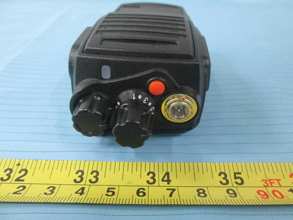
Click to zoom
Application Details
- Equipment Class
- TNF - Licensed Non-Broadcast Transmitter Held to Face
- Date of Grant
- Jun 10, 2015
- Application Purpose
- Original Equipment
- Date of Application
- Jun 10, 2015
- Equipment Note
- Two-Way Radio
- Frequency Range
- 136.00000000 - 174.00000000
- Country
- China
Documents & Files
Document Text
Text extracted from the exhibit documents filed with the FCC. Open a document above to read the original.
Users Manual
Introduction Thank you for purchasing PUXING Series Radio. The Series radios provide cost effective communica- tions for businesses, they are the perfect communications solution for all of todays fast-paced industries. Please read this guide carefully so you know how to properly operate the radio before use. 1.CONTENTS i Cautions................................................. Check equipment....................................... Battery pac k............................................. Charging................................................... Maintenance............................................. Start........................................................ Install/remove battery.............................. Install antenna....................................... Install belt clip...................................... Install speaker/microphone......................... Install the cover over the speaker/microphone jacks Controls................................................... Operations and settings........................... Busy channel lockout................................. Vox sensitivity........................................ TX powe r..................................................... Squelch level........................................... 1 2 3 4 5 6-8 6-7 7 7 8 8 9 10-16 10 10 10 10 Beep setting....................................... Channel annunciation........................... Time out time r.................................... CTCSS / DCS.......................................... Wide/narrow band................................ Emergency call..................................... Battery save....................................... End roge r............................................ Squelch tail elimination..................... Low battery warning........................... Cable clone...................................... PTT ID transmit mode......................... Flank key functions........................ Troubleshooting guide........................ Main techology data........................... 10 11 11 11 11 11 12 12 12 12 12-13 13 13-16 17 18 CAUTIONS 01 ■Do not expose the transceiver to long periods of direct sunlight, nor place it close to heating appliances. 01.CAUTIONS ■Before use this transceiver may need get local government authorization. ■DO NOT operate the transceiver without a proper antenna attached, as this may damage the transceiver and may also exceed exposure limits. ■Refer service to qualified technicians only. ■Turn off the transceiver while taking on fuel or while parked in a gasoline service station. ■If it appears that the transceiver diffuses peculiar smell or smoke, please shut off its power immediately, then contact with the nearest dealer. ■Don’t keep the transceiver transmitting too long .It may be too hot to hurt body or damage the transceiver itself. ■Please turn off the transceiver before entering the inflammable and explosive environment. 0 3.BATTERY PACK POW FULL BATTERY PACK 03 02.CHECK EQUIPMENT CHECK EQUIPMENT Welcome to use our transceiver. Please check if any damage to the packing box before use. Carefully unpacks the transceiver. We recommend that you identify the items listed in the following table. If any items are missing or have been damaged during shipment, please inform the seller. SUPPLIED ACCESSORIES ANTENNA Li-ion BATTERY CHARGER ADAPTOR BELT CLIP USERS’ MANUAL CHARGING THE BATTERY PACK The battery pack is not charged at the factory; charge it before use. Initially charging the battery pack after purchase or extended storage will not bring the battery pack to its normal operating capacity. After repeating the charge/discharge cycle two or three times, the capacity will increase to best status You should charge or change the battery pack if the battery’s power is weak. CAUTION: ●Use the original battery pack only. It is likely to explode or hurt your body if you use other battery. ●Don’t short-circuit the terminals or put it in fire. Don’t attempt to open the unit. ●The ambient temperature should be between 0* to 40* while charging is in progress. ●Charging beyond this range may not fully charge the battery. ●Always switch OFF the transceiver equipped with a battery pack before charging. Using the transceiver while charging, it will interfere with correct charging. ●Don’t cut off the power or take off the battery during the charging process or else it will interfere with correct charging. ●The battery pack life is over when its operating time decreases even though it is fully and correctly charged. Replace the battery pack. ●Don’t recharge the battery pack if it is already fully charged or it will short the life of the battery. ●Don’t charge the battery pack or transceiver while it is wet. Please wipe up it first to avoid danger. 04.CHARGING 04 CHARGING ■Put the DC plug of the transformer into the DC socket of the charger unit. ■Connected the supplied transformer to the AC jack ■Slide the battery or the transceiver with a battery pack into the charger. ■Make sure the battery pack contacts are in contact with the charging terminals, and the charger LED is on, it begins to charge. ■After charging the supplied battery pack for 4 hours, remove it or the transceiver equippe d with it from the charger. The charger light turns to green automatically after charging is completed. CAUTION: ●It is abnormal in case of the charger glisteningly before sliding the battery pack into the charger. ●Don’t replace the battery pack until the indicator light is stable. ●Make sure contact well, LED indicates red when it is charging, if LED always blinking the battery pack is damaged or over the environment temperature. MAINTENANCE 05 Charging Operation If the transceiver indicator displays , it means the battery pack is out of power , please charge it. Please always use the original charger. The charger’s indicator shows the charging status below. Please charge the battery pack as follow: 05.MAINTENANCE ■Don’t carry the transc…
Text truncated - open the document above for the full version.
External Photos
EXHIBIT B - EUT EXTERNAL PHOTOGRAPHS EUT – Front View EUT – Rear View EUT – Top View EUT – Bottom View EUT – Left View EUT – Right View EUT – Antenna View 1 EUT – Antenna View 2
ID Label/Location Info
EXHIBIT A - FCC ID LABELING AND LOCATION FCC ID Label Proposed FCC ID Label Location The label shown shall be permanently affixed at a conspicuous location on the device and be readily visible to the user at the time purchase (Labeling requirements per 2.925)
Internal Photos
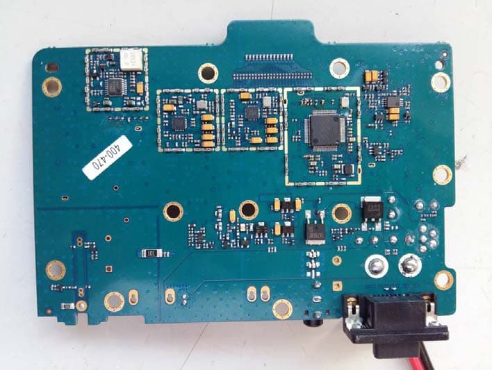
EXHIBIT C - EUT INTERNAL PHOTOGRAPHS EUT – Cover off View 1 EUT – Cover off View 2 EUT – Main Board Top View EUT – Main Board Bottom View
RF Exposure Info
Note: This test report is prepared for the customer shown above and for the device described herein. It may not be duplicated or used in part without prior written consent from Bay Area Compliance Laboratories Corp. SAR EVALUATION REPORT For Xiamen Puxing Electronics Science & Technology Co.Ltd. FL3-4 No.11,XiangHong Road,xiang’An District,Xiamen,China FCC ID: AUJPXDZ558V002 Report Type: Original report Product Type: Two way radio Test Engineer: Terry XiaHou Report Number: RSZ150515002-20 Report Date: 2015-05-26 Reviewed By: Bell Hu SAR Engineer Prepared By: Bay Area Compliance Laboratories Corp. (Shenzhen) 6/F, the 3rd Phase of WanLi Industrial Building, ShiHua Road, FuTian Free Trade Zone Shenzhen, Guangdong, China Tel: +86-755-33320018 Fax: +86-755-33320008 www.baclcorp.com.cn Bay Area Compliance Laboratories Corp. (Shenzhen) Report No: RSZ150515002-20 SAR Evaluation Report 2 of 64 Attestation of Test Results EUT Information Company Name Xiamen Puxing Electronics Science & Technology Co.Ltd. EUT Description Two way radio FCC ID AUJPXDZ558V002 Model Number 1) PX-558V( Test Model) 2) PX- 558D V ( Multiple Model) Test Date 2015-05-22 Frequency (MHz) Modulation Max. SAR Level(s) Reported (1g-SAR) Limit (W/Kg) 136-174 Digital 6.25kHz Face up: 0.517 W/kg Body-Back: 1.760 W/kg 8.0 Analog 12.5kHz Face up: 0.473 W/kg (corrected by Multiplying 50%.) Body-Back: 1.721 W/kg (corrected by Multiplying 50%.) Applicable Standards ANSI / IEEE C95.1: 2005 IEEE Standard for Safety Levels with Respect to Human Exposure to Radio Frequency Electromagnetic Fileds,3 kHz to 300 GHz. ANSI / IEEE C95.3: 2002 IEEE Recommended Practice for Measurements and Computations of Radio Frequency Electromagnetic Fields With Respect to Human Exposure to SuchFields,100 kHz—300 GHz. EN62209-2:2010 Human exposure to radio frequency fields from hand-held and body-mounted wireless communication devices – Human models, instrumentation, and procedures Part 2: Procedure to determine the specific absorption rate (SAR) for wireless communication devices used in close proximity to the human body (frequency range of 30 MHz to 6 GHz) IEEE1528:2013 IEEE Recommended Practice for Determining the Peak Spatial-Average Specific Absorption Rate (SAR) in the Human Head from Wireless Communications Devices: Measurement Techniques KDB procedures KDB 447498 D01 v05r02: Mobile and Portable Devices RF Exposure Procedures and Equipment Authorization Policies. KDB 865664 D01v01r03: SAR measurement 100 MHz to 6 GHz . KDB 643646D01 v01r01: SAR test Reduction Considerations for Occupational PTT Radios. KDB Inquiry: Tracking Number 316436 for SAR VHF system validation. Note: This wireless device has been shown to be capable of compliance for localized specific absorption rate SAR For Occupational /Controlled Exposure Environment limits specified in ANSI/IEEE Standards and have been tested in accordance with the measurement procedures specified in IEEE 1528-2013 and RF exposure KDB procedures. The results and statements contained in this report pertain only to the device(s) evaluated. Bay Area Compliance Laboratories Corp. (Shenzhen) Report No: RSZ150515002-20 SAR Evaluation Report 3 of 64 TABLE OF CONTENTS DOCUMENT REVISION HISTORY ......................................................................................................................... 4 EUT DESCRIPTION .................................................................................................................................................... 5 TECHNICAL SPECIFICATION ......................................................................................................................................... 5 REFERENCE, STANDARDS, AND GUILDELINES ............................................................................................... 6 SAR LIMITS ................................................................................................................................................................. 7 FACILITIES .................................................................................................................................................................. 8 DESCRIPTION OF TEST SYSTEM .......................................................................................................................... 9 EQUIPMENT LIST AND CALIBRATION ............................................................................................................. 16 EQUIPMENTS LIST & CALIBRATION INFORMATION .................................................................................................... 16 SAR MEASUREMENT SYSTEM VERIFICATION .............................................................................................. 17 LIQUID VERIFICATION ............................................................................................................................................... 17 SYSTEM ACCURACY VERIFICATION ........................................................................................................................... 19 SAR SYSTEM VALIDATION DATA ..................................................................................................................... 20 EUT TEST STRATEGY AND METHODOLOGY ................................................................................................. 24 TEST POSITIONS FOR DEVICE OPERATING NEXT TO A PERSON’S EAR........................................................................ 24 CHEEK/TOUCH POSITION ........................................................................................................................................... 25 EAR/TILT POSITION ................................................................................................................................................... 25 TEST POSITIONS FOR BODY-WORN AND OTHER CONFIGURATIONS .............................................................................. 26 SAR EVALUATION PROCEDURE .........................…
Text truncated - open the document above for the full version.
Test Setup Photos
EXHIBIT D - TEST SETUP PHOTOGRAPHS Transmitting Radiated Emissions (Below 1 GHz) Transmitting Radiated Emissions (Above 1 GHz)
Contact Information
Applicant
KEVIN XIE
Test Firm
Bay Area Compliance Laboratory Corp. (Shenzhen)John Chan
Technical Specifications
| # | Rule Parts | Frequency Range | Power Output | Emission | Tolerance |
|---|---|---|---|---|---|
| 4 | 9 | 136 MHz - 174 MHz | 1 W | 5K29FXD | 1.05 ppm |
Other Applications from Xiamen Puxing Electronics Science & Technology Co.,Ltd.
AUJPXDZMD720U
Sep 20, 2015DMR Mobile Radio
Equipment Class
TNB - Licensed Non-Broadcast Station Transmitter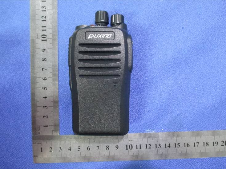
AUJPXDZPD508
May 27, 2015DPMR RADIO
Equipment Class
TNF - Licensed Non-Broadcast Transmitter Held to Face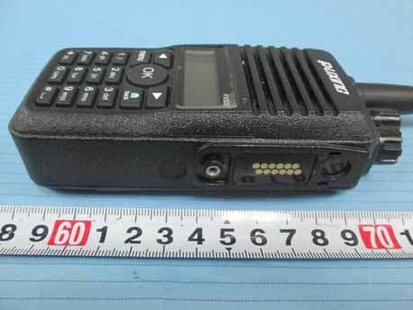
AUJPXDZ800V002
Aug 24, 2014Two Way Radio
Equipment Class
TNF - Licensed Non-Broadcast Transmitter Held to Face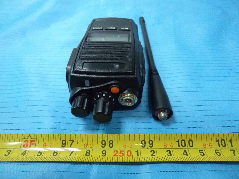
AUJPXDZ558V001
Apr 01, 2014Two Way Radio
Equipment Class
TNF - Licensed Non-Broadcast Transmitter Held to Face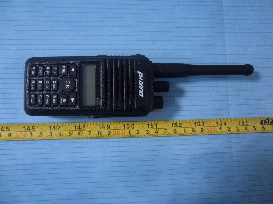
AUJPXDZ800U002
Mar 05, 2014Two Way Radio
Equipment Class
TNF - Licensed Non-Broadcast Transmitter Held to Face