AXAKRC121107-1Base station
HARRIS CORPORATION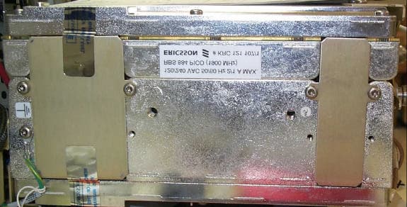
Click to zoom
Application Details
- Equipment Class
- PCB - PCS Licensed Transmitter
- Date of Grant
- May 17, 2001
- Application Purpose
- Original Equipment
- Date of Application
- Apr 03, 2001
- Equipment Note
- Base station
- Frequency Range
- 1930.00000000 - 1990.00000000
- Company
- HARRIS CORPORATION
- Country
- United States
Documents & Files
Document Text
Text extracted from the exhibit documents filed with the FCC. Open a document above to read the original.
Users Manual
E RBS 884 Pico (1900 MHz) User Guide AE/LZB 119 3834 P1D 2001-04-04© Ericsson Radio Systems AB 2001 – All Rights Reserved The contents of this document are subject to revision without notice due to continued progress in methodology, design, and manufacturing. Eric sson shall have no liability for any error or damages of any kind resulting from the use of this document. i001 52-AE/LZB 119 3834 Uae Rev P1D 2001-04-04 Table of Contents Part 1RBS 884 Pico (1900 MHz) Introduction. . . . . . . . .1-1 1Introduction ................... 1-3 2ReasonforReissue............... 1-3 3AboutthisUserGuide .............. 1-3 Part2SystemDescription ................... 2-1 1Introduction ................... 2-3 2Overview .................... 2-3 3Architecture ................... 2-7 4Equipment Configurations. . . . . . . . . . . .2-28 5TechnicalData .................. 2-33 Part3RBS884Pico(1900MHz)CRIInstallation ........ 3-1 1Introduction ................... 3-3 2SafetyPrecautions ................ 3-3 3ElectrostaticDischarge .............. 3-5 4GeneralInformation ............... 3-6 5Unpacking .................... 3-9 6SitePreparation ................. 3-11 7PrerequisitesandTools .............. 3-13 8Cabinet Installation Procedures. . . . . . . . . .3-15 9CRI Hardware Units and Switches. . . . . . . . .3-50 10Equipment Cabling and Start-up . . . . . . . . . .3-62 Part 4RBS 884 Pico (1900 MHz) Radio Head Installation. . . .4-1 1Introduction ................... 4-3 2SafetyPrecautions ................ 4-3 3GeneralInformation ............... 4-4 4Unpacking .................... 4-4 5SiteSelectionandPreparation.......... 4-5 6PrerequisitesandTools .............. 4-8 7RadioHeadSet-up ................ 4-9 8EquipmentInstallation .............. 4-25 Part 5Integration and Test, RBS 884 Pico (850 MHz and 1900MHz) ....................... 5-1 1Introduction ................... 5-3 2SafetyRegulations ................ 5-4 3ProductHandling ................. 5-5 4Tools ...................... 5-6 5Integration:Pico850/1900MHz .......... 5-6 6RBS 884 Pico CRI Test Procedure: Pico 850/1900 MHz...................... 5-66 001 52-AE/LZB 119 3834 Uae Rev P1D 2001-04-04ii Contents 7RBS 884 Pico Radio Head Test Procedure: Pico850/1900MHz............... 5-66 8Installation Test Procedure: Pico 850/1900 MHz. .5-67 9Example Integration: Pico (850 MHz). . . . . . .5-76 10Example Integration: Pico (1900 MHz). . . . . .5-157 Part6OperationsandMaintenance .............. 6-1 1Introduction ................... 6-3 2MaintenanceOverview .............. 6-3 3SafetyRegulations ................ 6-4 4ProductHandling ................. 6-5 5Fault Detection and Alarms Reporting. . . . . . .6-6 6HardwareReplacement .............. 6-9 Part 7Troubleshooting. . . . . . . . . . . . . . . . . . . .7-1 1Introduction ................... 7-3 2Troubleshooting ................. 7-3 3PrerequisitesandTools .............. 7-4 4FaultIsolationandRepair ............. 7-5 Part8GlossaryofTerms ................... 8-1 Part9AcronymsandAbbreviations .............. 9-1 AppendixARFGuidelines ..................... A-1 1Introduction ................... A-3 2GeneralDescription ............... A-3 3TransmissionPath ................ A-6 4LinkBudget ................... A-7 5Operations and Maintenance. . . . . . . . . . .A-9 Appendix BRBS 884 Pico (1900 MHz) Spare Parts Catalog. . . . .B-1 1GeneralInformation ............... B-3 2Product Location and Referencing. . . . . . . . .B-4 Appendix CTest Record Form for RBS 884 Pico . . . . . . . . . . .C-1 1Introduction ................... C-3 2TestRecordForms ................ C-3 AppendixDUserFeedback ..................... D-1 1Introduction ................... E-1 2OrderingofCustomerManuals .......... E-1 3ProblemSolving ................. E-1 4TroubleReporting ................ E-1 AppendixEConversionTable .................... E-1 1Introduction ................... E-3 2ConversionTable................ E-3 iii001 52-AE/LZB 119 3834 Uae Rev P1D 2001-04-04 List of Figures FigureTitlePage Figure2-1RBS884Pico(1900MHz)Components ....... 2-4 Figure 2-2General Overview of RBS 884 Pico (1900 MHz) Configuration................. 2-9 Figure 2-3RBS 884 Pico (1900 MHz) Functional and Implementation Units .................... 2-11 Figure2-4CRIRackMountEquipment.......... 2-14 Figure2-5CRIFloorMountEquipment.......... 2-15 Figure2-6CRIFloorMountCabinetLayout ......... 2-16 Figure2-7CRIInterconnections............. 2-17 Figure2-8ELIUnitwithCascadedRadioHeads ....... 2-19 Figure2-9CRIInternalAlarmDistribution......... 2-21 Figure2-10RadioHeadwithMonopoleAntennas ....... 2-22 Figure2-11RadioHeadBlockDiagram ........... 2-23 Figure2-12RadioHeadMonopoleAntennas ......... 2-25 Figure2-13RadioHeadDualPatchAntenna ......... 2-25 Figure2-14RadioHeadUserInterface ........... 2-27 Figure 2-15RBS 884 Pico (1900 MHz) with Leased Connections, Example.................. 2-29 Figure 2-16RBS 884 Pico (1900 MHz) CRI at the MSC, Example2-30 Figure 2-17RBS 884 Pico (1900 MHz) with Non-Leased Connections, Example.................. 2-31 Figure2-18MacroSitewithPicoELIandRadioHeads.... 2-33 Figure 3-1ESD Wrist Strap and Cable Connected to the Cabinet.3-6 Figure3-2TypicalCableLabel ............... 3-7 Figure3-3HardwareUnitConnections ............ 3-8 Figure3-4MinimumBendingRadius............ 3-8 Figure 3-5Example of an N-Connector (Can also be Angl ed). .3-9 Figure3-6UnpackingTransportationCrate ......... 3-11 Figure3-7CRIRackMountSubrack........... 3-17 Figure3-8SettingtheCabinetIdentifier.......... 3-18 Figure3-9CRIRackMount ............... 3-20 Figure3-10MarkingtheFixingHoleLocations ........ 3-21 Figure 3-11Anchor Bolt Spacing for RBS Pico Equipment Base.3-21 Figure3-12DrillingtheFixingHoles............ 3-22 Figure3-13InstallingtheBaseBolts ............ 3-23 Figure3-14InsertingAnchorsintheDrilledHoles ....... 3-23 Figure3-15LevelingtheRearoftheBase .......... 3-24 Figure 3-16Leveling the Sides o ftheBase......... 3-25 Figure3-17TighteningtheBaseBolts........... 3-26 001 52-AE/LZB 119…
Text truncated - open the document above for the full version.
Users Manual
RBS 884 Pico (1900 MHz) Radio Head Installation 8.2.2Patch Antenna Installation Preparations 1.Verify that the monopole antenna brackets are removed from the Radio Head (Step 4 on page 4-25 and Step 5 on page 4-26). Attaching the External Duplexer Cables 2.Remove two (2) patch antenna cables from the RH Patch Antenna Kit NTM/KRE 101 1608, and attach the cables to the external duplexers as shown in Figure 4-13 on page 4-31. Patch Antenna Cable Duplexer Patch Antenna Cable Patch Antenna Cable Duplexer Patch Antenna Cable Wall TXRX TX Figure 4-13. Patch Antenna to Duplexer Cables 3.Verify that the duplexer-TRX cable connectors are securely attached. 2/1531-AE/LZB 119 3834 Uae Rev PA6 2001-04-044-31 RBS 884 Pico (1900 MHz) Radio Head Installation Attaching the Patch Antenna Assembly Caution ! Mount the Radio Head on the wall prior to installing the patch antenna assembly to guard against possible damage to the patch antenna assembly. 4.Attach the patch antenna assembly to the Radio Head using the six screws provided with the antenna. See Figure 4-14 on page 4-32 for an illustration of the six screw locations. Patch Antenna Cables Patch Antenna Assembly Mounting Screw Locations Figure 4-14. Patch Antenna Assembly and Cables 4-322/1531-AE/LZB 119 3834 Uae Rev PA6 2001-04-04 RBS 884 Pico (1900 MHz) Radio Head Installation Attaching Antenna Cables 5. Warning! Use care when handling the antenna connectors. Connect the patch antenna cables from the external duplexer to the press-fit connectors on each end of the patch antenna. See Figure 4-14 on page 4-32 for the location of the patch antenna cables. 8.3Cable Installation and Power-Up The RBS 884 Pico (1900 MHz) Radio Heads may be connected to Pico CRI equipment using leased T1/E1 connections or non-leased proprietary connections. All T1 cable must be plenum rated, CAT5, 24-gauge UTP cable. E1 cable may either be 75-ohm coaxial or 120-ohm twisted-pair cable. The maximum cable length for propriety connection is 1,000 m eters, without interconnects or splices. Preparations 1.Verify that the Control and Radio Interface ( CRI) has been installed. If not, refer toPart 3 RBS 884 Pico (1900 MHz) CRI Installationin this user’s guide. 2.Ensure that the following tools and materia ls are available prior to starting this installation procedure: 2/1531-AE/LZB 119 3834 Uae Rev PA6 2001-04-044-33 RBS 884 Pico (1900 MHz) Radio Head Installation •T1 –100-ohm CAT5, UTP with RJ-45 connectors –Ferrites (included in Small Parts Kit NTM 201 2887/1) –Power Cord (The United States (US) 110 Vac power cord is included in Radio Head Hardware Kit NTM 201 1581/1. For other markets, the power cords are customer supplied.) –Wire/cable strippers and cutters –Crimping tool •E1 –120-ohm TP with RJ-45 connectors or 75-ohm coaxial cable with BNC connectors –Ferrites (included in Small Parts Kit NTM 201 2887/1) –Power Cord (The 110 Vac power cord is included in Radio Head Hardware Kit NTM 201 1581/1. Other power cords are customer-supplied.) –Impedance Matching Network, 75 to 120-ohm (Figure 4-15 on page 4-34) –Short lengths of E1 120-ohm twisted-pair cable with RJ-45 fittings for connection fr om Impedance Matching Networks to Radio Heads –Wire/cable strippers and cutters –Crimping tool RX In TX Out G.703 75-120 Adapter 120 Ohm Figure 4-15. Impedance Ma tching Network for E1 75-ohm Coaxial Cable 4-342/1531-AE/LZB 119 3834 Uae Rev PA6 2001-04-04 RBS 884 Pico (1900 MHz) Radio Head Installation Route CRI to Radio Head Cable 3. DANGER! Do not install T1/E1 PCM cable close to fluorescent light fixtures, transformers, or electric motors. For cabling practices, see “Commercial Building Standard for Telecommunications Pathways and Spaces, EIA/TIA-569.” If the CRI is remote and the line to the CRI is leased, install a C hannel Service Unit (CSU) and route a T1/E1 PCM cable from the CSU to the first Radio Head (Radio Head 1). If the CRI is local and the line to the CRI is proprietary or non-leased, route the cable direc tly from the local CRI to Radio Head 1. Refer to Table 4-8 on page 4-35 for the technical specifications for the PCM connections. Note:For installation convenience, the CRI to Radio Head cabling information is also included inPart 3 RBS 884 Pico (1900 MHz) CRI Installation. Table 4-8.PCM Connection Specifications Type of ConnectionSpecifications Proprietary non-leased line 800 to 1000 m with a maximum attenuation of 30 dB T1/E1Receiver sensitivity: -105 dBm (3% BER with diversity) Clock: Stratum 2 or better Install Connectors (100/120-ohm Cable) 4.Attach an RJ-45 connector to the T1 100-ohm or E1 120-ohm PCM cable using the pinout information in Figure 4-16 on page 4-36 and Table 4-9 on page 4-36. Note:When looking into the back of an RJ-45 connector with the latch tab down, pin 1 is on the extreme left of the connector cable opening. 2/1531-AE/LZB 119 3834 Uae Rev PA6 2001-04-044-35 RBS 884 Pico (1900 MHz) Radio Head Installation PCM Cable Quarter-Plug Connector PCM Cable RJ-45 Connector 02 08 Quarter-Plug Connector Cable View A02 A BC + - - + White/Blue Blue White/Orange Orange PCM IN PCM OUT } } C02 C04 C06 C08 < < < < > > > > 2 1 4 5 CRIControl and Radio Interface PCMPulse Code Modulation Figure 4-16. Pinouts for 100/120-ohm PCM Cable Table 4-9.Pinouts for 100/120–ohm PCM Cable Transmission Recommended Wire Color RJ-45 Pin Number Quarter Pin Number White-blue1C02PCM In Blue-white2C04 White-orange4C06PCM Out Orange-white5C08 Install 75 to 120-ohm Impedance Matching Network and Connectors (E1 Only) 5.Install a 75 to 120-ohm Impedance Matching Network at the Radio Head. Refer to Figure 4-15 on page 4-34. 6.Attach BNC connectors to each end of the coaxial cable and connect one end to the 75 to 120-ohm Impedance Matching Network. 4-362/1531-AE/LZB 119 3834 Uae Rev PA6 2001-04-04 RBS 884 Pico (1900 MHz) Radio Head Installation 7.Attach RJ-45 connectors to each end of a short length of 120-ohm cable as specified in Table 4-10 on page 4-37. Note:Pin 1 is on the extreme left of th…
Text truncated - open the document above for the full version.
Users Manual
Operations and Maintenance 6Hardware Replacement When a faulty unit has been determined either by indications at the MSC, by routine maintenance checks, or by using the troubleshooting procedure, the unit can be replaced by following the appropriate procedure in this section. Warning! If possible avoid“hot repair”of CRI units. Hot repair is the process of replacing a failed unit without powering down the CRI cabinet. Before replacing any unit, contact the MSC for further assistance. The MSC may have to block one or more units before they can be replaced. 6.1Prerequisites and Tools 6.1.1Prerequisites Before a faulty magazine or unit can be replaced, the replacement magazine or unit must be available and have the same or higher R-state number (R-state letters do not matter). For example, product number ROF 134 8002/1 R3B can be replaced with product number ROF 134 8002/1 R3C, but not with ROF 134 8002/1 R4A. 6.1.2Tools and Materials The following tools are recommended for the equipment replacement procedures: •ESD wrist strap with "banana" connector •Extractor tool for removing cards (handle and button) •Cable connector torque wrench set including: –Torque wrench (preset to 0.6 Nm and 2.8 Nm) –Torx bit TX10 and TX8 for circuit board screws –SMA tool for coaxial cables •Flat blade screwdriver set for power and data cable connectors •Phillips screwdriver set 1/1541-AE/LZB 119 3834 Uae Rev PA6 2001-04-046-9 Operations and Maintenance •Torx screwdrivers TX20 and TX30 •T1 or E1 test set with cables •8-position crimping hand tool •RJ-45 connectors •Side-cutting pliers •Metric socket set with 100 mm and 300 mm extension bars •Torque wrench with socket adapter •Small soldering iron •Multimeter (voltmeter and ohmmeter) •Electric light •Cable ties and cable tie gun •Extra ESD bag 6.2CRI Hardware Replacement 6.2.1CID Unit Replacement CID Unit Removal 1. Warning! Contact the MSC for authority to proceed before removing the Cabinet Identification (CID) Unit. One o r more CRI units may have to be blocked at the MSC before starting this procedure. Remove the door from the front of the CRI cabinet. 2.Attach the ESD strap to your wrist and connect the free end of the strap cable to an appropriate groun d conductor on the cabinet. 3.Verify that all the status LEDs on the front of the printed circuit boards in the CRI are off indicating that the units are blocked. If the LEDs are not off, contact the MSC for further assistance. 6-101/1541-AE/LZB 119 3834 Uae Rev PA6 2001-04-04 Operations and Maintenance 4.Record the settings for the two rotary switches on the CID Unit. See Figure 6-1 on page 6-11 for the location of the CID Unit rotary switches. Note:The CID Unit is located on the bottom left side of the CRI rack mount (subrack) and on the top left side of the CRI floor mount (cabinet). Error LEDs CID CRI Cabinet Identification Control and Radio Interface 01 2 3 4 5 678910 11 12 13 14 15A B C D E F Power Error CID Unit D-Type Connector Rotary Switches CRI Rack Mount CRI Magazine (BGM 136 69) 01 2 3456 7 8 9 1011 12131415 AB C D E Po we r Err or 01 2 3 4 5 678910 11 12 13 14 15 AB C D E Power Error Setting the CID Rotary Switches CRI Magazine CRI Floor Mount Fan 1 Fan 2 Power LEDs Figure 6-1.CID Unit 5.Disconnect the CID cable from the D-type connector on the CID Unit. See Figure 6-1 on page 6-11 for the location of the D-type connector on the CID Unit. 6.Using a Torx screwdriver, remove the two Torx screws that connect the CID Unit to t he CRI subrack or cabinet. 1/1541-AE/LZB 119 3834 Uae Rev PA6 2001-04-046-11 Operations and Maintenance Unit Replacement 7.Install the new CID unit using the two Torx screws in Step 6 on page 6-11 and tighten the screws. 8.Reconnect the CID cable from the DC/DC converter unit to the CID Unit. 9.Using a small, flat-head screwdriver, set the rotary switches to the same settings recorded in Step 4 on page 6-11. See Figure 6-1 on page 6-11. 10.Remove the ESD strap and cable. 11.Notify the MSC operator that the new CID unit is ready for operation and testing. 12.Reinstall the door on the front of the CRI cabinet. Unit Repair 13.Complete the Repair Traveler Note. Describe in detail the circumstances and symptoms of the fault. 14.Attach the Repair Traveler Note to the unit. 15.Use the packaging material from the replacement fan unit to repackage the suspected faulty CID unit. 16.Return the CID unit to the service center. 17.Update the Site Inventory list in theSite Installation Documentation with the replacement CID unit details. 6-121/1541-AE/LZB 119 3834 Uae Rev PA6 2001-04-04 Operations and Maintenance 6.2.2Power Supply Replacement Power Supply Removal 1. Warning! Contact the MSC for authority to proceed before removing the power supply unit. Disconnect the power cord from the AC outlet. 2.Attach the ESD strap to your wrist and connect the free end of the strap cable to an appropriate ground conductor on the cabinet. 3.If the power supply is mounted in a subrack, loosen the two screws that hold the power supply tray to the power shelf. 4.If the power supply is mounted in a floor mount cabinet, remove the top cover by loosening the two rear bolts and removing the two front bolts that secure it to the power supply shelf. 5.Slide the power supply tray off the power shelf. 6.Disconnect the power cord from the AC connector on the rear panel of the power supply. See theCRI Top Viewillustr ationinFigure 6-2 on page 6-14. 1/1541-AE/LZB 119 3834 Uae Rev PA6 2001-04-046-13 Operations and Maintenance Power Supply Top View DC Power Cable (Y-Cable) (RPM 113 1476/1) Right DC Filter Power Shelf AC Power Cord (RPM 945 324) AC Power Cord (RPM 945 324) DC Power Cable (Y-Cable) (RPM 113 1476/1) Power Supply Left DC Filter AC Connector Fan Power Cable (RPM 513 941 00900) CRI Front View Figure 6-2.CRI Power Supply 7.Disconnect the DC power ca ble (RPM 113 1476) from the power supply. See theCRI Top Viewillustration in Figure 6-2 on page 6-14. 8.Remove the four screws that hold the power supply to the…
Text truncated - open the document above for the full version.
Cover Letter(s)
April 4, 2001 FCC OET Lab Attention: Equipment Authorization Branch Subject: Certification for FCC ID:AXAKRC121107-1 Gentlemen, Ericsson Inc. requests a grant for Certification for the above mentioned FCC Identifier. This TDMA technology base station transceiver is designed for use in the 1900 MHz Domestic Public Cellular Radiotelephone Communications Services, as per Part 24. It meets the requirements of IS-138A for operation in cellular systems. Documents governing TDMA were used as a guide. This system is exempt from measurements and calculations for MPE as defined in 47 CFR 1.1307 Table 1. Ericsson Inc. requests confidentiality under 47 CFR 0.459 for the following exhibits listed: Exhibit 4Block Diagrams Exhibit 5Circuit Diagrams Exhibit 10Alignment Procedure Exhibit 12Operational Description The design utilizes custom circuitry and proprietary in the AXAKRC121107-1 system. The Operational Description and Alignment exhibits provide unique information regarding service/alignment codes. To protect Ericsson’s competitive advantage on these proprietary techniques and alignment codes, we request the above listed exhibits be held as confidential and withheld from the Public Information File. Sincerely, Jim Sponsler Regulatory Engineer [email protected] Tel No:(919) 472-6460
Cover Letter(s)
April 27, 2001 FCC OET Lab Attention: Equipment Authorization Branch Subject: Certification for FCC ID:AXAKRC121107-1 Gentlemen, Ericsson Inc. requests a grant for Certification for the above mentioned FCC Identifier. This TDMA technology base station transceiver is designed for use in the 1900 MHz Domestic Public Cellular Radiotelephone Communications Services, as per Part 24. It meets the requirements of IS-138A for operation in cellular systems. Documents governing TDMA were used as a guide. This system is exempt from measurements and calculations for MPE as defined in 47 CFR 1.1307 Table 1. One option the customer may order with the unit is a patch antenna. The patch antenna is shown in the internal photos, has a 14dBi gain. This gain was unintentionally not listed on the 731 form. Per Mr. R. Fabina, I have updated the cover letter and resubmitted it to act as the notice of the alternate antenna. Ericsson Inc. requests confidentiality under 47 CFR 0.459 for the following exhibits listed: Exhibit 4Block Diagrams Exhibit 5Circuit Diagrams Exhibit 10Alignment Procedure Exhibit 12Operational Description The design utilizes custom circuitry and proprietary in the AXAKRC121107-1 system. The Operational Description and Alignment exhibits provide unique information regarding service/alignment codes. To protect Ericsson’s competitive advantage on these proprietary techniques and alignment codes, we request the above listed exhibits be held as confidential and withheld from the Public Information File. Sincerely, Jim Sponsler Regulatory Engineer [email protected] Tel No:(919) 472-6460
External Photos
APPLICANT:Exhibit 3 FCC ID NO: ERICSSON INCAXAKRC121107-1 ©2001 Ericsson Inc. 03/23/01 1 3/23/01 APPLICANT:Exhibit 3 FCC ID NO: ERICSSON INCAXAKRC121107-1 ©2001 Ericsson Inc. 03/23/01 2 APPLICANT:Exhibit 3 FCC ID NO: ERICSSON INCAXAKRC121107-1 ©2001 Ericsson Inc. 03/23/01 3 APPLICANT:Exhibit 3 FCC ID NO: ERICSSON INCAXAKRC121107-1 ©2001 Ericsson Inc. 03/23/01 4
ID Label/Location Info
APPLICANT:Exhibit 1 FCC ID NO: ERICSSON INCAXAKRC121107-1 03/23/01©2001 Ericsson Inc.1 FCC ID Label
Internal Photos
APPLICANT:Exhibit 9 FCC ID NO: ERICSSON INCAXAKRC121107-1 03/29/01©2001 Ericsson Inc. 1 Example 1 Bottom View of Power Supply Board Example 2 Bottom View of RHI Board APPLICANT:Exhibit 9 FCC ID NO: ERICSSON INCAXAKRC121107-1 03/29/01©2001 Ericsson Inc. 2 Example 3 Top View of Power Supply and TRX Boards Example 4 Top View of RHI and TRX Boards APPLICANT:Exhibit 9 FCC ID NO: ERICSSON INCAXAKRC121107-1 03/29/01©2001 Ericsson Inc. 3 Example 5 Bottom View of TRX Boards. APPLICANT:Exhibit 9 FCC ID NO: ERICSSON INCAXAKRC121107-1 03/29/01©2001 Ericsson Inc. 4 Top side of Patch antenna Bottom side of metal plate APPLICANT:Exhibit 9 FCC ID NO: ERICSSON INCAXAKRC121107-1 03/29/01©2001 Ericsson Inc. 5 Back side of Patch antenna PWB and metal plate
Test Report
APPLICANT:FCC ID NO: ERICSSON INCAXAKRC121107-1 © 2001 Ericsson Inc. Exhibit 6 INDEX OF TEST RESULTS Exhibit #Description 6A1900MHz/Part 24/TDMA: RF Power Stability 6B1900MHz/Part 24/TDMA: Modulation Characteristics 6C1900MHz/Part 24/TDMA: Occupied bandwidth 6D1900MHz/Part 24/TDMA: Spurious Emissions (conducted) 6E1900MHz/Part 24/TDMA: Spurious Emissions (radiated) 6F1900MHz/Part 24/TDMA: Frequency Stability APPLICANT:FCC ID NO: ERICSSON INCAXAKRC121107-1 © 2001 Ericsson Inc. EXHIBIT 6A1 1900 MHz TDMA RF POWER OUTPUT Para. 2.1033 (c)(6)(7), 2.1046 and 24.232 (a)(c) The RF maximum power measured at the output terminal (antenna connector) was 20 dBm at 1960 MHz. Note: The manufacturers rated voltage RBS is 110/220 VAC. The measurements were made per using the following equipment: Hewlett Packard Spectrum Analyzer Model 8563E Hewlett Packard Universal Counter Model 53131A Hewlett Packard AC Power Source Model 6813A Gigatronics Universal Power Meter Model 8651A Thermotron SM-8C Temperature Chamber APPLICANT:FCC ID NO: ERICSSON INCAXAKRC121107-1 © 2001 Ericsson Inc. Exhibit 6B1 1900 MHz TDMA MODULATION CHARACTERISTICS 2.1047(c)(13) The transceiver shall be capable of generating π/4 shifted differentially encoded quadrature phase shift keying signals. The transmitted signal is given by: S(t) = Σ g(t-nT) cos (φn) cos (ωct) - Σ g(t-nT) sin (φn) sin (ωct) where g(t) is the pulse shaping function that corresponds to a square root raised cosine baseband filter with roll off factor of 0.35, ωc is the radian carrier frequency, T is the symbol period, and φn is the absolute phase corresponding to the nth symbol interval. The symbol rate (1/T) is 24.3 k symbols /sec.} The modulation accuracy requirement is specified by setting limits on the RMS difference between the actual transmitted signal waveform and the ideal signal waveform. The ideal waveform is derived mathematically from the specification of modulation shown above. The specified requirement is error vector magnitude. For this measurement, frequency accuracy shall meet the requirements of Section 3.1 prior to measurement. The average carrier frequency error is the difference between the average carrier frequency of the actual transmitted waveform and the average signal waveform carrier frequency. The ideal modulation is defined above. The definition is such that, observing an ideal transmitter through an ideal root raised-cosine receiver filter at the correct sampling instants one symbol apart would result in the sequence of values given by: j{π/4+B(k)*π/2} S(k)=S(k-1)e where B(k) = 0,1,2,3 according to the following table: XkYkB(k) 000 011 112 103 In the forward channel, S(k) forms part of a continuous data stream. In the reverse channel, the transit bursts from the mobile are truncated by power up and down ramping. In this case, S(6) is the first sample that enters into demodulation, which yields the first two information bits by comparing S(6) with S(7). The last information bits lie in the comparison of S(162) and S(161). The ideal transmit and receive filters in cascade form a raised cosine Nyquist filter having an impulse response going through zero at symbol period intervals, so there is no inter-symbol interference at the ideal sampling points. The ideal signal sampler therefore, take on one of the eight values defined above, at the output of the receive filter. This section defines how the output signal from a transmitter is to be evaluated against the ideal signal. APPLICANT:FCC ID NO: ERICSSON INCAXAKRC121107-1 © 2001 Ericsson Inc. Let Z(k) be the complex vectors produced by observing the real transmitter through an ideal measuring receive filter at instants k, one symbol period apart. With S(k) defined as above, the transmitter is modeled as: k Z(k) = [C0 + C1 * [S(k)+E(k)]] * W where: k = n/24.3KHz dr=jda W = eaccounts for both a frequency offset giving “da” radians per symbol phase rotation and an amplitude changes of “dr” nepers per symbol: C0 is a constant origin offset representing quadrature modulator imbalance, C1 is a complex constant representing the arbitrary phase and output power of the transmitter, and E(k) is the residual vector error on sample S(k) The sum square vector error is then: k=MAXk=MAX | || |E(k)| || |2 |{[Z(k) * W -C0]/C1} -S(k)| k = MINk = MIN C0, C1 and W shall be chosen to minimize this expression and are then used to compute the individual vector errors E(k) on each symbol. The symbol timing phase of the receiver output samples used to compute the vector error shall also be chosen to give the lowest value. The values of MAX and MIN for the reverse channel (mobile station transmitter) are: MIN = 6 MAX= 162 The RMS vector error is then computed as the square root of the sum-square vector divided by the number of symbols in the slot, (157 in the reverse direction). Method of Measurement Connect the mobile station to the Standard Test Source and Modulation Accuracy Equipment. Modulate the Standard Test Source with pseudo-random Data Field bits. The mobile station shall transpond the Data Field bits using the TDMAON command. Use the Modulation Accuracy Measurement Equipment to measure the modulation accuracy of the mobile station. Minimum Standard The RMS vector error in any burst shall be less than 12.5%. APPLICANT:FCC ID NO: ERICSSON INCAXAKRC121107-1 © 2001 Ericsson Inc. Exhibit 6C1 1900 MHz: OCCUPIED BANDWIDTH Per 2.1049 (h) and 24.238 (a)(b)(c)(d) the exhibits presented show the modulation that has to exist in a 1900 MHz Cellular System. All the exhibits listed below are plots where the modulation condition is Psuedorandom Data (48.6 kb/s switched), operating in the TDMA mode. All plots were taken while transmitting at Power Level 0. Any frequency span not covered in the exhibits below was found to be unaffected by the transmitter/modulation. EXHIBIT Lower Channel (Example, Channel 2) Normal bursted operation; data rate 48.6 kb/s, Output power level 0. 6C21 MHz Resolution Bandwidth reference plot. 6C3 …
Text truncated - open the document above for the full version.
Contact Information
Applicant
Thomas Camper, Jr.(Regulatory Manager)
Technical Contact
Ericsson IncJim Sponsler
[email protected]919-472-6460
7001 Development Drive · Research Triangle Park, North Carolina · United States
Non-Technical Contact
Ericsson IncJim Sponsler
[email protected]919-472-6460
Technical Specifications
| # | Rule Parts | Frequency Range | Power Output | Emission | Tolerance |
|---|---|---|---|---|---|
| 1 | 24E | 1.93 GHz - 1.99 GHz | 2.5 W | 40K0DXW | 0.1000000000 ppm |
Other Applications from HARRIS CORPORATION

AXATR-423-A2
Jul 14, 2004CM-42
Equipment Class
PCB - PCS Licensed Transmitter
AXATR-420-A2
Mar 21, 2002DM-15
Equipment Class
TNB - Licensed Non-Broadcast Station Transmitter
AXATR-422-A2
Mar 13, 2002Dual Mode TDMA Cellular Handset
Equipment Class
TNE - Licensed Non-Broadcast Transmitter Held to Ear
AXATR-421-A2
Dec 19, 2001Dual Mode TDMA Cellular Transceiver
Equipment Class
TNE - Licensed Non-Broadcast Transmitter Held to EarAXATR-413-A2
Aug 14, 2001cellular/pcs portable terminal
Equipment Class
PCE - PCS Licensed Transmitter held to ear