AXATR-396-A2GSM Portable Terminal
HARRIS CORPORATION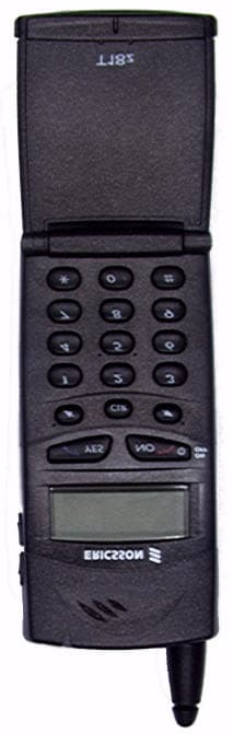
Click to zoom
Application Details
- Equipment Class
- PCE - PCS Licensed Transmitter held to ear
- Date of Grant
- Oct 21, 1999
- Application Purpose
- Original Equipment
- Date of Application
- Aug 12, 1999
- Equipment Note
- GSM Portable Terminal
- Frequency Range
- 1850.00000000 - 1910.00000000
- Company
- HARRIS CORPORATION
- Country
- United States
Documents & Files
Document Text
Text extracted from the exhibit documents filed with the FCC. Open a document above to read the original.
Users Manual
Register your new phone, purchase Ericsson original accessories, and see the latest in products by visiting us at: www.ericsson.com/us/consumerX/99 PBMThis manual is published by Ericsson Inc., without any warranty. Improvements and changes to this manual necessitated by typog raphical errors, inaccuracies of current information, or improvements to programs and/or equipment, may be made by Ericsson Inc., at any time and without notice. Such changes will, however, be incorporated into new editions of this manual.All rights reserved.Ericsson Inc., 1999.Publication Number: LZT 123 1422 PA4Printed in the U.S.A. T18z User’s Guide Some menus/features are operator dependent. 1 Guidelines for Safe and Efficient Use . . . . . 5Safety . . . . . . . . . . . . . . . . . . . . . . . . . . . . . . . . . . . . . . . . .5Driving . . . . . . . . . . . . . . . . . . . . . . . . . . . . . . . . . . . . . . .7Phone Care and Operation . . . . . . . . . . . . . . . . . . . . . . . .7Battery Information . . . . . . . . . . . . . . . . . . . . . . . . . . . . . .8Preparing Your Phone for Use . . . . . . . . . . 10T18z Components . . . . . . . . . . . . . . . . . . . . . . . . . . . . . .10Assembly . . . . . . . . . . . . . . . . . . . . . . . . . . . . . . . . . . . . .10The SIM Card . . . . . . . . . . . . . . . . . . . . . . . . . . . . . . . . .10The Battery . . . . . . . . . . . . . . . . . . . . . . . . . . . . . . . . . . .11The Display, Keys, and Menus . . . . . . . . . . 13Turning Your Phone On/Off . . . . . . . . . . . . . . . . . . . . .13Display Messages . . . . . . . . . . . . . . . . . . . . . . . . . . . . . . .13Display Icons . . . . . . . . . . . . . . . . . . . . . . . . . . . . . . . . . .14Key Functions . . . . . . . . . . . . . . . . . . . . . . . . . . . . . . . . .15Active Flip . . . . . . . . . . . . . . . . . . . . . . . . . . . . . . . . . . . .15Navigating the Menu System . . . . . . . . . . . . . . . . . . . . . .16Making and Receiving Calls . . . . . . . . . . . . 18Making a Call . . . . . . . . . . . . . . . . . . . . . . . . . . . . . . . . .18Ending a Call . . . . . . . . . . . . . . . . . . . . . . . . . . . . . . . . . .19 Making International Calls . . . . . . . . . . . . . . . . . . . . . . 19Making Emergency Calls . . . . . . . . . . . . . . . . . . . . . . . . 19Receiving Calls . . . . . . . . . . . . . . . . . . . . . . . . . . . . . . . . 19During a Call . . . . . . . . . . . . . . . . . . . . . . . . . . . . . . . . . 20 Your Phone Book . . . . . . . . . . . . . . . . . . . . 22Entering Characters . . . . . . . . . . . . . . . . . . . . . . . . . . . . 22Storing a Number Together with a Name . . . . . . . . . . . 23Overwrite Protection . . . . . . . . . . . . . . . . . . . . . . . . . . . 24Using the Phone Book . . . . . . . . . . . . . . . . . . . . . . . . . . 25Keeping the Phone Book Up to Date . . . . . . . . . . . . . . . 25Copying Phone Numbers Between Memories . . . . . . . . 26Using the Call List . . . . . . . . . . . . . . . . . . . . . . . . . . . . . 27Calling Line Identification (CLI) . . . . . . . . . . . . . . . . . . 28Personalizing Your Phone . . . . . . . . . . . . . 30Ring Signal Volume . . . . . . . . . . . . . . . . . . . . . . . . . . . . 30Ring Signal Type . . . . . . . . . . . . . . . . . . . . . . . . . . . . . . 30Your Own Ring Signals . . . . . . . . . . . . . . . . . . . . . . . . . 32Vibrating Unit . . . . . . . . . . . . . . . . . . . . . . . . . . . . . . . . 32Minute Minder . . . . . . . . . . . . . . . . . . . . . . . . . . . . . . . 32Message Signal . . . . . . . . . . . . . . . . . . . . . . . . . . . . . . . . 33Key Sound . . . . . . . . . . . . . . . . . . . . . . . . . . . . . . . . . . . 33 Table of Contents Some menus/features are operator dependent.2Display Light . . . . . . . . . . . . . . . . . . . . . . . . . . . . . . . . . 33Display Language . . . . . . . . . . . . . . . . . . . . . . . . . . . . . . 33Greeting Text . . . . . . . . . . . . . . . . . . . . . . . . . . . . . . . . . 33Phone Number Display . . . . . . . . . . . . . . . . . . . . . . . . . 34Time . . . . . . . . . . . . . . . . . . . . . . . . . . . . . . . . . . . . . . . . 34Date . . . . . . . . . . . . . . . . . . . . . . . . . . . . . . . . . . . . . . . . 35Auto Store . . . . . . . . . . . . . . . . . . . . . . . . . . . . . . . . . . . 35Master Reset . . . . . . . . . . . . . . . . . . . . . . . . . . . . . . . . . . 35Mail Services . . . . . . . . . . . . . . . . . . . . . . . . 37Short Message Service . . . . . . . . . . . . . . . . . . . . . . . . . . . 37Enabling the Phone to Send SMS . . . . . . . . . . . . . . . . . . 37Enhancing Your Text Messages . . . . . . . . . . . . . . . . . . . 37Composing a Text Message . . . . . . . . . . . . . . . . . . . . . . 38Sending a New Text Message . . . . . . . . . . . . . . . . . . . . . 38Sending a Stored Message . . . . . . . . . . . . . . . . . . . . . . . . 39Receiving a Message . . . . . . . . . . . . . . . . . . . . . . . . . . . . 39Reading a Stored Message . . . . . . . . . . . . . . . . . . . . . . . . 40Replying to a Message . . . . . . . . . . . . . . . . . . . . . . . . . . . 41Erasing a Message . . . . . . . . . . . . . . . . . . . . . . . . . . . . . . 41Storing Incoming Messages . . . . . . . . . . . . . . . . . . . . . . . 41Own Messages . . . . . . . . . . . . . . . . . . . . . . . . . . . . . . . . 42Area Information . . . . . . . . . . . . . . . . . . . . . . . . . . . . . . 43Voicemail . . . . . . . . . . . . . . . . . . . . . . . . . . . . . . . . . . . . 45 Forwarding Calls . . . . . . . . . . . . . . . . . . . . . 46Activating Call Forward . . . . . . . . . . . . . . . . . . . . . . . . . 46Forwarding When the Data Menus are On . . . . . . . . . . . 46Checking the Forward Status . . . . . . . . . . . . . . . . . . . . . 47Canceling Call Forwards . . . . . . . . . . . . . . . . . . . . . . . . . 47Canceling All Call Forwards . . . . . . . . . . . . . . . . . . . . . . 47Security . . . . . . . .…
Text truncated - open the document above for the full version.
Attestation Statements
APPLICANT:FCC ID NO: ERICSSON INC.AXATR-396-A2 ©1999 Ericsson Inc. EXHIBIT 2A Protection Against Unauthorized ESN and Firmware Upgrades: The Electronic Serial Number (SNR) is part of the IMEI number of the phone. The IMEI bits in this phone are encoded and spread over various nonsequential memory locations in order to prevent detection and modification. Once the factory has programmed the IMEI, the mobile firmware cannot overwrite or alter the IMEI memory locations. Both the IMEI host and operation systems components are permanently mounted to the mobile in order to prevent removal and misuse. Unauthorized attempts to alter the mobile’s firmware will cause the unit to become inoperable. APPLICANT:FCC ID NO: ERICSSON INC.AXATR-396-A2 ©1999 Ericsson Inc. EXHIBIT 2B Certification of Data The technical data contained in this application has been taken personally or under my supervision, and is certified true and correct. My qualifications include over fourteen years of experience in the communications industry. Product Test and Support Engineering 8/13/99 Date
Cover Letter(s)
August 13, 1999 Federal Communications Commission Authorization & Evaluation Division 7435 Oakland Mills Road Columbia, Maryland 21046 Attention: Equipment Authorization Branch Subject:Type Acceptance for FCC ID:AXATR-396-A2 Gentlemen, Ericsson Inc. requests a grant of Certification for the above mentioned FCC Identifier. This portable transceiver is designed for use in the GSM 1900 cellular telephone system. The mobile operates in the 1900 MHz per 47 CFR Part 24. It meets the requirements of GSM1900 11.10-1 version 4.19.1 specification for operation in GSM cellular systems. The mobile was tested and found compliant with 47 CFR Part 15. Measurements and calculations for SAR have been made on this radio. This unit complies with IEEE C95.1-1991 (ANSI/IEEE C95.1-1992). The mobile operates in a temperature range of –20 to +60 degree C. This range is specified in the GSM air interface document. Employing temperature protection in the mobile controls the operating temperature range. Upon the temperature of the mobile exceeding this range, the mobile shuts down as indicated in the power versus temperature and frequency versus temperature plots. Ericsson Inc. requests confidentiality under 47 CFR 0.459 for the following exhibit listed: Exhibit 4Block Diagrams Exhibit 5Circuit Diagrams Exhibit 10Parts List and Tune Up Information Exhibit 12Operational Description Exhibits 4, 5, 10 and 12 are marked CONFIDENTIAL on the electronic filing submission. Justification of this request for confidentiality is to protect Ericsson’s competitive advantage on the design of the power amplifier and a unique method of implementing modulation. To protect Ericsson’s competitive advantage on these proprietary techniques, we request the above listed exhibit be held as confidential and withheld from the Public Information File. Sincerely, Jim Sponsler Regulatory Services Research Triangle Park, NC 27709 Tel:(919) 472-6460 Fax:(919) 472-6382
External Photos
APPLICANT:Exhibit 3 FCC ID NO: ERICSSON INCAXATR-396-A2 ©1999 Ericsson Inc. APPLICANT:Exhibit 3 FCC ID NO: ERICSSON INCAXATR-396-A2 ©1999 Ericsson Inc.
ID Label/Location Info
APPLICANT:Exhibit 1 FCC ID NO: ERICSSON INCAXATR-396-A2 ©1999 Ericsson Inc.
Internal Photos
APPLICANT:Exhibit 9 FCC ID NO: ERICSSON INCAXATR-396-A2 ©1999 Ericsson Inc. APPLICANT:Exhibit 9 FCC ID NO: ERICSSON INCAXATR-396-A2 ©1999 Ericsson Inc. APPLICANT:Exhibit 9 FCC ID NO: ERICSSON INCAXATR-396-A2 ©1999 Ericsson Inc.
RF Exposure Info
Confidential REPORT 1(1) Prepared (also subject responsible if other)No. RT/EUS/TR/X Mark Douglas919-472-6334 EUS/VRX-99:1078 ApprovedCheckedDateRevFile EUS/TR/X Mark DouglasMGD1999-08-02A U:\FCC_TRNS\Fcc_396 PatE2\exhibit11\T18z (Patricia Emily, retractable half-wave).doc E SAR Assessment Measurements Test Report for the Ericsson T18z Single Mode Telephone Electromagnetic Near Field and Radio Frequency Dosimetry Laboratory Research Triangle Park, NC, USA Test Equipment: DescriptionAsset NumberDue Date DASY3 DAE V1s/n 3459909 E-field probe ETDV5s/n 13370003 Dielectric probe kit HP 85070Binv. 557339908 Network analyzer HP 8752Cinv. 572480007 Power meter HP 437Binv. 492929909 Power sensor HP 8482Hinv. 8210-33869909 Radio Comm. Analyzer Anritsu MT8801Bs/n MB124779909 Dipole Validation Kit, D900V2s/n 0350003 Dipole Validation Kit, D1800V2s/n 2170001 Test approved: Mark Douglas, Ph.D. Confidential REPORT 2(2) Prepared (also subject responsible if other)No. RT/EUS/TR/X Mark Douglas919-472-6334 EUS/VRX-99:1078 ApprovedCheckedDateRevFile EUS/TR/X Mark DouglasMGD1999-08-02A U:\FCC_TRNS\Fcc_396 PatE2\exhibit11\T18z (Patricia Emily, retractable half-wave).doc E 1. Introduction In this test report, Specific Absorption Rate (SAR) measurements for the Ericsson T18z portable telephone are presented. The measurements were conducted at the dosimetry laboratory at Ericsson, Inc. in Research Triangle Park, North Carolina, USA. The report describes the test procedures that were used and the test results that were recorded. 2. Device Under Test (D.U.T.) • Antenna Description: Type Retractable half-wavelength monopole Location Back and right length extended117 mm length retracted25 mm Dimensions diameter at base9 mm Configuration Retractable • Portable Telephone Description: Device name T18z Serial number GA2B01QVVP Certification Number AXATR-396-A2 Mode PCS 1900 Multiple Access Scheme TDMA Duty Cycle 1 / 8 Peak Power Nominal 30 dBm Center Frequency 1880 MHz 3. Measurement System The measurements were made with the Dosimetric Assessment System, DASY, from Schmid & Partner AG (SPEAG) in Zurich, Switzerland. This system was developed by Professor Niels Kuster and his team at the Swiss Federal Institute of Technology (ETH) in Zurich, Switzerland [II]. The system uses the implantable E-field probe technique to evaluate the SAR inside the generic twin phantom. The E-field is automatically scanned inside the phantom filled with a brain tissue simulating liquid [III]. The positioning of the E-field probe inside the left phantom head is done by a high-precision 6 axis robot. A computer is used to control the robot and to collect the measured data. 3.1 Specification for the E-Field probe The following is a summary of the technical data for the E-field probe that is used for the measurements. • Sensitivity in tissue simulating liquid:1 μW/g to 100 mW/g • Linearity:< ± 0.2 dB • Deviation from isotropy in tissue, • Normal to probe axis:± 0.2 dB • In all planes, all polarizations:± 0.8 dB • Spatial resolution of SAR measurements:< 0.125 cm 3 • Reproducibility of probe positioning:< ± 0.2 mm Confidential REPORT 3(3) Prepared (also subject responsible if other)No. RT/EUS/TR/X Mark Douglas919-472-6334 EUS/VRX-99:1078 ApprovedCheckedDateRevFile EUS/TR/X Mark DouglasMGD1999-08-02A U:\FCC_TRNS\Fcc_396 PatE2\exhibit11\T18z (Patricia Emily, retractable half-wave).doc E A more detailed description of the system is given in references [I] and [II]. 3.2 Brain tissue simulating liquid data The electrical data used for the brain tissue simulating liquid are according to the data provided by C. Gabriel. The liquid is prepared using the recipe [V] for the brain tissue simulating liquid. The electrical parameters of the brain tissue simulating liquid are measured at room temperature by the HP 85070B dielectric probe kit from Hewlett Packard. This probe kit uses an open-ended coaxial probe and a network analyser to measure the electrical data for the liquid. The following values were measured for the relative permittivity (εε r ) and conductivity (σσ) for the liquids that were used during the SAR measurements. f ( MHz ) 1800 εε r 40.2 σσ ( S/m ) 1.68 The depth of the brain tissue simulating liquid was 14.6cm. The SAR measurements were performed at a room temperature of 23.0 °C. 3.3 Calibration The system is calibrated at fixed time intervals by the supplier of the system (SPEAG). The E-field probes are calibrated every 12 months by the supplier. A detailed description of probe calibration is found in reference [IV]. 3.4 Validation Immediately before measuring the SAR of the device under test, the measurement system was validated by measuring the SAR of a standard dipole antenna located a set distance underneath a flat phantom. The measured results are compared with expected values that are recorded in reference documents. The results are given below. 1 gram averaged SAR (W/kg) DipoleOutput Power (W) ExpectedMeasured difference (%) D1800V2112.912.53.1 3.5 Measurement Tolerance The total measurement uncertainty is estimated to be ±25% [II]. 4. Test Procedure The dosimetric assessment measurements are made according to the operating manual for the DASY3 system from SPEAG. A base station simulator was used to control the phone during the SAR measurements. The phone was supplied with a fully-charged battery for the tests. The SAR is measured at three frequencies (corresponding to the low, middle and high frequencies of the band). 4.1 Positioning of the Device Under Test The D.U.T. is placed in a position against the phantom head that corresponds to the intended or normal operating position. The normal position is a position that is convenient and provides good acoustic coupling. Appendix 3 shows pictures of the position used for the measurements. The position is defined as follows: Confidential REPORT 4(4) Prepared (also subject responsible if other)No. RT/EUS/TR/X Mark Douglas919-472-6334 EUS/VRX-99:1078 ApprovedCheckedDateRevFile EUS/TR/X Ma…
Text truncated - open the document above for the full version.
Test Report
APPLICANT: FCC ID NO: ERICSSON INC AXATR-396-A2 © 1999 Ericsson Inc. EXHIBIT 6A1 1900MHz GSM RF POWER OUTPUT Para. 2.1033 (c,6,7), 2.1046 The RF power measured at the output terminals (antenna connector) is plotted against supply voltage variation and temperature variations at the highest levels. Exhibit Voltage (V) Temperature TX Freq Power Level 6A2Varied+25CMid Band0 6A34.8VariedMid Band0 The measurements were made the following equipment: HP6623A DC Power SupplyHP 8593 E Spectrum Analyzer HP 8566 B Spectrum AnalyzerThermotron SM-8C Temperature Chamber HP 8922 M System Simulator EFFECTIVE RADIATED POWER The following is a description of the substitution method used to obtain accurate EIRP readings at the carrier fundamental frequency: (1) EUT measurements are made at 3 m using calibrated antennas and equipment with known cable losses. (2) A peak measurement is made by raising and lowering the antenna and rotating the EUT 360 degrees. Horizontal and vertical polarization data is recorded. (3) A generator and dipole antenna are then substituted for the EUT. The dipole antenna is a half-wave dipole. If a dipole antenna cannot be used, then the designated antenna is referenced to a dipole antenna. (4) Measurements are made through the dipole antenna at known power levels to determine the system calibration factors at a given frequency. (5) At frequencies where no calibration data is taken, the value is interpolated between the closest data point above and below the transmit frequency. Calibration data is taken with a half-wave dipole antenna. Table: Power comparison chart for all modes – SAR versus radiated power Modef (MHz)SAR (dBm) Radiated (dBm/W) 185031.0 29.26 / .843 1879 31.2 29.08 / .810 GSM 190931.429.96 / .991 APPLICANT: FCC ID NO: ERICSSON INCAXATR-396-A2 © 1999 Ericsson Inc. Exhibit 6A2 RF power across PCS band @ PL0 vs. Supply Voltage 30.7 30.7 30.8 30.8 30.9 30.9 31.0 31.0 31.1 31.1 31.2 4.34.44.54.64.74.84.95.05.15.25.3 V Measured power /dBm CH 660 APPLICANT: FCC ID NO: ERICSSON INCAXATR-396-A2 © 1999 Ericsson Inc. Exhibit 6A3 RF power across PCS band @ PL0 vs. Temperature 30.2 30.3 30.4 30.5 30.6 30.7 30.8 30.9 31 31.1 31.2 -30-25-20-100102030405060 Temperature/ 0 C RF Power/dBm CH 660 APPLICANT: FCC ID NO: ERICSSON INCAXATR-396-A2 © 1999 Ericsson Inc. EXHIBIT 6B1 1900 MHz GSM MODULATION CHARACTERISTICS Para: Part 2.987 (a)(b)(d) and Part 24 4. Modulation This chapter defines the theoretical requirements of the modulator, inclusive of the differential encoder. The modulator receives the bits from the encryption unit and produces an RF modulated signal. The information bits are first differentially encoded and then passed to the modulator. The modulation is GMSK (Gaussian Minimum Shift Keying) with a BT product of 0.3. 4.1Modulation Format 4.1.1Modulating Bit Rate The modulating bit rate is 1/T = 1625/6 kb/s (approximately 270.833 kb/s). 4.1.2Start And Stop Of The Burst The bits contained within a burst are defined in chapter 2. For the purpose of the modulator specification that follows, the bits entering the differential encoder prior to the first bit of the burst and following the last bit of the burst are consecutive logical ones and are denoted by the term dummy bits which define the start and end points of the useful and active parts of the burst as shown in Figure 4.1. The actual state of these bits is left to the manufacturer’s implementation subject to the requirement that all performance specifications of this volume are met. Nothing is specified about the actual phase of the modulator output signal outside of the useful part of the burst. Figure 4.1 depicts the relationship between the active and useful part of the burst, the tail bits and dummy bits for a normal burst. The useful part of the burst lasts for 147 modulating bits. Output phase The useful part The active part dummy bits 111111... 3 tail bits ...000 1/2 bit 3 tail bits 000... dummy bits ...111111 1/2 bit Figure 4.1: Normal Burst 4.1.3Differential Encoding Each data value d i = [0,1] is differentially encoded. The output of the differential encoder is: ˆ d i =d i ⊕d i − 1 where⊕denotes modulo 2 addition. The modulating data value α i input to the modulator is: α i =1−2 ˆ d i where α i ∈ {-1,1} APPLICANT: FCC ID NO: ERICSSON INCAXATR-396-A2 © 1999 Ericsson Inc. 4.1.4Filtering The modulating data values α i as represented by Dirac pulses excite a linear filter with impulse response defined by: g(t)=h(t)⊗rect t T where the function rect(x) is defined by: rect t T = 1 T for t< T 2 rect t T =0 otherwise and ⊗ means convolution. h(t) is defined by: h(t)= e -t 2 2σ 2 T 2 2πσT where σ = ln(2) 2πBT and BT=0.3 where B is the 3 dB bandwidth of the filter with impulse response h(t), and T is the duration of one input data bit. 4.1.5Output Phase The phase of the modulated signal is: φ (t') =α i i ∑ π hg(u)du −∞ t ' − iT ∫ where the modulating index h is 1/2 (maximum phase change in radians is /2 per data interval). The time reference t' = 0 is the start of the active part of the burst as shown in Figure 4.1. This is also the start of the bit period of bit number 0 (the first tail bit) as defined in chapter 2. 4.1.6Modulation The modulated RF carrier, except for start and stop of the TDMA burst may therefore be expressed as: x(t') = 2E c T cos2 π f 0 t' +φ (t') +φ 0 () where E c is the energy per modulating bit, f 0 is the center frequency and φ 0 is a random phase and is constant during one burst. APPLICANT: FCC ID NO: ERICSSON INCAXATR-396-A2 ©1999 Ericsson Inc. EXHIBIT 6C1 1900 MHz: OCCUPIED BANDWIDTH Per 2.989 (c, l, h) and 24.238 (a,b,c,d) the exhibits presented show the modulation that have to exist in a 1900 MHz Cellular System. All the exhibits listed below are plots where the modulation condition is Psuedorandom Data (270.833 kb/s switched), operating in the GSM mode. All plots were taken while transmitting at Power Level 0. Any frequency span not covered at …
Text truncated - open the document above for the full version.
Contact Information
Applicant
Thomas Camper, Jr.(Regulatory Manager)
Technical Contact
Ericsson IncJim R Sponsler
(919) 472-6460
7001 Development Drive · RTP, North Carolina · United States
Non-Technical Contact
Ericsson IncJim R Sponsler
[email protected](919) 472-6460
Technical Specifications
| # | Rule Parts | Frequency Range | Power Output | Emission | Tolerance |
|---|---|---|---|---|---|
| 1 | - | 1.85 GHz - 1.91 GHz | 1 W | 258KGXW | 1.0000000000 ppm |
Other Applications from HARRIS CORPORATION

AXATR-423-A2
Jul 14, 2004CM-42
Equipment Class
PCB - PCS Licensed Transmitter
AXATR-420-A2
Mar 21, 2002DM-15
Equipment Class
TNB - Licensed Non-Broadcast Station Transmitter
AXATR-422-A2
Mar 13, 2002Dual Mode TDMA Cellular Handset
Equipment Class
TNE - Licensed Non-Broadcast Transmitter Held to Ear
AXATR-421-A2
Dec 19, 2001Dual Mode TDMA Cellular Transceiver
Equipment Class
TNE - Licensed Non-Broadcast Transmitter Held to EarAXATR-413-A2
Aug 14, 2001cellular/pcs portable terminal
Equipment Class
PCE - PCS Licensed Transmitter held to ear