B2K-4336822ARFID Module
Oki Electric Industry Co., Ltd.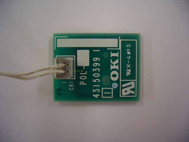
Click to zoom
Application Details
- Equipment Class
- DXX - Part 15 Low Power Communication Device Transmitter
- Date of Grant
- Dec 19, 2005
- Application Purpose
- Original Equipment
- Date of Application
- Dec 19, 2005
- Equipment Note
- RFID Module
- Frequency Range
- 13.56000000 - 13.56000000
- Country
- Japan
Documents & Files
Document Text
Text extracted from the exhibit documents filed with the FCC. Open a document above to read the original.
Users Manual
Plate-Inner Plate-Shield-RFID 1. To assemble Board-RFID to Plate-Shield-RFID with two screws. RFID Assy – PCB 2. To assemble RFID Assy-PCB to Plate-Inner with two screws. Film Board-RFID after assembly Plate Assy – Inner (4336821A) Plate Assy-Inner (4336821A) Cover-Top(Sub) To assemble Head-Cable, Holder-Head, Cover–Top(Sub) and etc to Plate Assy – Inner (4336821A) with 8 screws. Cover Assy - Top Printer-Unit Cover Assy - Top To assemble Cover Assy –Top to Printer-Unit. FCC WARNING Changes or modifications not expressly approved by the party responsible for compliance could void the user’s authority to operate the equipment. NOTICE This equipment has been tested and found to comply with the limits for a Class B digital device, pursuant to part 15 of the FCC Rules. These limits are designed to provide reasonable protection against harmful interference in a residential installation. This equipment generates, uses and can radiate radio frequency energy and, if not installed and used in accordance with the instructions, may cause harmful interference to radio communications. However, there is no guarantee that interference will not occur in a particular installation. If this equipment does cause harmful interference to radio or television reception, which can be determined by turning the equipment off and on, the user is encouraged to try to correct the interference by one or more of the following measures: -Reorient or relocate the receiving antenna -Increase the separation between the equipment and receiver. -Connect the equipment into an outlet on a circuit different from that to which the receiver is connected. -Consult the dealer or an experienced radio/TV technician for help.
Users Manual
RF-ID TAG Toner cartridge
Test Report
Test report No. : 26BE0100-HO-2b Page : 2 of 16 Issued date : October 12, 2005 Revised date : November 29, 2005 FCC ID : B2K-4336822A UL Apex Co., Ltd. Head Office EMC Lab. 4383-326 Asama-cho, Ise-shi, Mie-ken 516-0021 JAPAN Telephone : +81 596 24 8116 Facsimile : +81 596 24 8124 MF060b(10.04.03) CONTENTS PAGE SECTION 1: Client information............................................................................................ 3 SECTION 2: Equipment under test (E.U.T.) ....................................................................... 3 SECTION 3: Test specification, procedures & results ........................................................ 4 SECTION 4: Operation of E.U.T. during testing................................................................. 6 SECTION 5: Conducted Emissions....................................................................................... 8 SECTION 6: Radiated emissions (Fundamental and Spurious Emissions and Bandwidth) 9 APPENDIX 1: Photographs of test setup............................................................................ 10 Conducted emissions .............................................................................................................. 10 Radiated emissions ................................................................................................................. 11 APPENDIX 2: Test instruments .......................................................................................... 12 APPENDIX 3: Data of EMI test .......................................................................................... 13 Conducted emissions .............................................................................................................. 13 Radiated emissions (Fundamental and Spurious emissions : below 30MHz) ................... 14 Radiated emissions (Spurious emissions : above 30MHz) .................................................. 15 –20dB Bandwidth and 99% Occpied Bandwidth ................................................................ 16 Test report No. : 26BE0100-HO-2b Page : 3 of 16 Issued date : October 12, 2005 Revised date : November 29, 2005 FCC ID : B2K-4336822A UL Apex Co., Ltd. Head Office EMC Lab. 4383-326 Asama-cho, Ise-shi, Mie-ken 516-0021 JAPAN Telephone : +81 596 24 8116 Facsimile : +81 596 24 8124 MF060b(10.04.03) SECTION 1: Client information Company Name : Oki Data Corporation Address : 3-1, Futaba-cho, Takasaki-shi, Gunma, 370-8585 Japan Telephone Number : +81-27-328-6183 Facsimile Number : +81-27-328-6396 Contact Person : Toshikazu Ito SECTION 2: Equipment under test (E.U.T.) 2.1 Identification of E.U.T. Type of Equipment : Embedded RFID Read/Write System Model No. : 4336822A Serial No. : 3 (for Conducted emissions test), 8 (for other tests) Country of Manufacture : Japan Rating : DC 5.0V Receipt Date of Sample : September 30, 2005 Condition of EUT : Production prototype (Not for Sale: This sample is equivalent to mass-produced items.) 2.2 Product Description Oki Data Corporation, Model No: 4336822A is the RFID module. The clock frequency of EUT is 13.56MHz (ASIC), 105.9375KHz(RFID module). (Transmitter) Equipment Type : Transmitter Frequency of operation : 13.56MHz Type of modulation : ASK Mode of operation : Simplex Antenna Type : Loop coil antenna Antenna Connector Type : PH2 (JST) Method of Frequency Generation : Crystal Operating voltage (inner) : DC 3.3V±0.1V Operating Temperature : +0 deg. C. - +50 deg. C. (Receiver) Type of Receiver : BPSK Demodulator Frequency of operation : 13.56MHz Intermediate frequency : 847.5kHz Method of Frequency Generation : Crystal Operating voltage (inner) : DC 3.3V±0.1V Operating Temperature : +0 deg. C. - +50 deg. C. FCC 15.31 (e) This EUT provides stable voltage(DC3.3V) constantly to RF Module regardless of input voltage. Therefore, this EUT complies with the requirement. FCC Part 15.203 Antenna requirement It is impossible for end users to replace the antenna, because the antenna is mounted inside of Printer. Therefore, the equipment complies with the antenna requirement of Section 15.203. Test report No. : 26BE0100-HO-2b Page : 4 of 16 Issued date : October 12, 2005 Revised date : November 29, 2005 FCC ID : B2K-4336822A UL Apex Co., Ltd. Head Office EMC Lab. 4383-326 Asama-cho, Ise-shi, Mie-ken 516-0021 JAPAN Telephone : +81 596 24 8116 Facsimile : +81 596 24 8124 MF060b(10.04.03) SECTION 3: Test specification, procedures & results 3.1 Test Specification Test Specification : FCC Part15 Subpart C : 2005 Title : FCC 47CFR Part15 Radio Frequency Device Subpart C Intentional Radiators Section 15.207 Conducted limits Section 15.205 Restricted bands of operation Section 15.209 Radiated emission limits, general requirements. 3.2 Procedures and results No. Item Test Procedure Specification Remarks Deviation Worst margin Results 1 Conducted emissions ANSI C63.4:2003 7. AC powerline conducted emission measurements FCC Section 15.207 ConductedN/A 11.1dB, AV 0.15042MHz N Complied 2 Electric Field Strength of Fundamental Emission ANSI C63.4:2003 13. Measurement of intentional radiators FCC Section 15.209 Radiated N/A 28.9dB 13.55955MHz 90 deg. Complied 3 Electric Field Strength of Spurious Emissions ANSI C63.4:2003 13. Measurement of intentional radiators FCC Section 15.205 FCC Section 15.209 Radiated N/A 6.0dB 311.866MHz, 298.307MHz, 230.504MHz Horizontal Complied 4 -20dB Bandwidth ANSI C63.4:2003 13. Measurement of intentional radiators FCC Section 15.215 Radiated N/A N/A Complied Note: UL Apex’s EMI Work Procedures No.QPM05 and QPM15. Uncertainty: *In case of the margin below the EMC Head Office’s uncertainty. The data listed in this report meets the limits unless the uncertainty is taken into consideration. Conducted Emission The measurement uncertainty (with a 95% confidence level) for this test was ±1.3dB. The data listed in this test report has enough margin, more than the site margin. Spurious Emission (Radiated) The measurement uncertainty (with a 9…
Text truncated - open the document above for the full version.
Test Setup Photos
Test report No. : 26BE0100-HO-2b Page : 10 of 16 Issued date : October 12, 2005 Revised date : November 29, 2005 FCC ID : B2K-4336822A UL Apex Co., Ltd. Head Office EMC Lab. 4383-326 Asama-cho, Ise-shi, Mie-ken 516-0021 JAPAN Telephone : +81 596 24 8116 Facsimile : +81 596 24 8124 MF060b(10.04.03) APPENDIX 1: Photographs of test setup Conducted emissions Front Rear Test report No. : 26BE0100-HO-2b Page : 11 of 16 Issued date : October 12, 2005 Revised date : November 29, 2005 FCC ID : B2K-4336822A UL Apex Co., Ltd. Head Office EMC Lab. 4383-326 Asama-cho, Ise-shi, Mie-ken 516-0021 JAPAN Telephone : +81 596 24 8116 Facsimile : +81 596 24 8124 MF060b(10.04.03) Radiated emissions Front Rear
Contact Information
Applicant
Masafumi Uchino
Technical Contact
UL Apex Co., LtdKenichi Adachi
[email protected]+81-596-24-8116
4383-326 Asama-cho · Ise-shi, Mie-ken · Japan
Non-Technical Contact
UL Apex Co., LtdKanako Sanda
[email protected]+81-596-24-8116
Test Firm
UL Japan, IncMitsuru Fujimura
Technical Specifications
| # | Rule Parts | Frequency Range | Power Output |
|---|---|---|---|
| 1 | 15C | 13.56 MHz - 13.56 MHz | - |
Other Applications from Oki Electric Industry Co., Ltd.
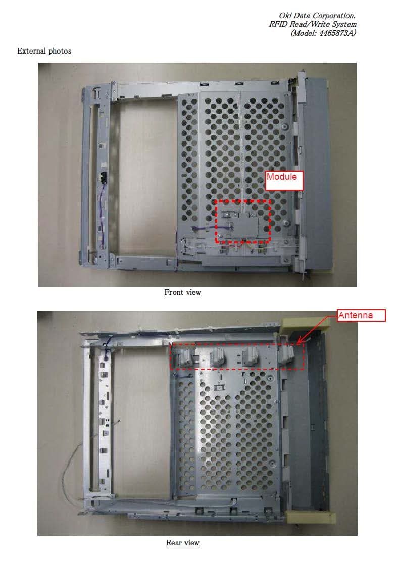
B2K-4465873A
Nov 05, 2014Embedded RFID Read/Write System
Equipment Class
DXX - Part 15 Low Power Communication Device Transmitter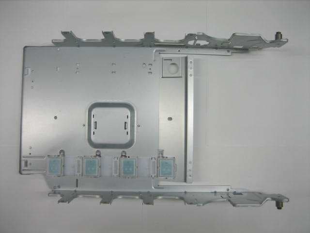
B2K-4399025A
Sep 25, 2012Embedded RFID Read/Write System
Equipment Class
DXX - Part 15 Low Power Communication Device Transmitter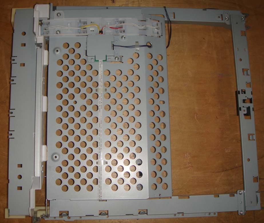
B2K-4465872A
Feb 27, 2012Embedded RFID Read/Write System
Equipment Class
DXX - Part 15 Low Power Communication Device Transmitter
B2K-4465871A
Jul 12, 2011Embedded RFID Read/Write System
Equipment Class
DXX - Part 15 Low Power Communication Device Transmitter
B2K-4399024A
Sep 08, 2010Embedded RFID Read/Write System
Equipment Class
DXT - Part 15 Low Power Transceiver, Rx Verified