B32MX870RFIDCredit Card Verification System
VeriFone Inc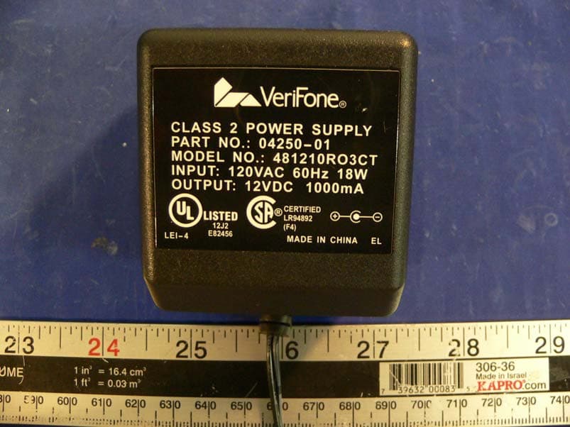
Click to zoom
Application Details
- Equipment Class
- DXX - Part 15 Low Power Communication Device Transmitter
- Date of Grant
- Jul 06, 2005
- Application Purpose
- Original Equipment
- Date of Application
- Jul 06, 2005
- Equipment Note
- Credit Card Verification System
- Frequency Range
- 13.56000000 - 13.56000000
- Company
- VeriFone Inc
- Country
- United States
Documents & Files
Document Text
Text extracted from the exhibit documents filed with the FCC. Open a document above to read the original.
Users Manual
Part Number 23431, Revision B.2 V E R I F O N E C O N F I D E N T IA L T E M P L A T E R E V E M x 800 Series Installation Guide All rights reserved. No part of the contents of this document may be reproduced or transmitted in any form without the written permission of VeriFone, Inc. The information contained in this document is subject to change without notice. Although VeriFone has attempted to ensure the accuracy of the contents of this document, this document may include errors or omissions. The examples and sample programs are for illustration only and may not be suited for your purpose. You should verify the applicability of any example or sample program before placing the software into productive use. This document, including without limitation the examples and software programs, is supplied “As-Is.” VeriFone, Inc. 2099 Gateway Place, Suite 600 San Jose, CA, 95110 USA www.verifone.com Part Number 23431, Revision B.2 M x 800 Series Installation Guide © 2005 VeriFone, Inc. VeriFone, the VeriFone logo, Omni, VeriCentre, Verix, and ZonTalk are registered trademarks of VeriFone. Other brand names or trademarks associated with VeriFone’s products and services are trademarks of VeriFone, Inc. All other brand names and trademarks appearing in this manual are the property of their respective holders. Comments? Please e-mail all comments on this document to your local VeriFone Support Team. M X 800 SERIES INSTALLATION GUIDE3 CONTENTS PREFACE . . . . . . . . . . . . . . . . . . . . . . . . . . . . . . . . . . . . . . . 5 Intended Audience . . . . . . . . . . . . . . . . . . . . . . . . . . . . . . . . . . . . . . . . . . . . . . . . 5 Document Organization . . . . . . . . . . . . . . . . . . . . . . . . . . . . . . . . . . . . . . . . . . . . 5 Conventions Used in This Document . . . . . . . . . . . . . . . . . . . . . . . . . . . . . . . . . . 5 Abbreviations . . . . . . . . . . . . . . . . . . . . . . . . . . . . . . . . . . . . . . . . . . . . . . . . . . . . 6 CHAPTER1 Features Overview. . . . . . . . . . . . . . . . . . . . . . . . . . . . . . . . . . . . . . . . . . . . . . . . . . . . . . . . 7 M x 800 Series . . . . . . . . . . . . . . . . . . . . . . . . . . . . . . . . . . . . . . . . . . . . . . . . . 7 Features and Benefits . . . . . . . . . . . . . . . . . . . . . . . . . . . . . . . . . . . . . . . . . . . . . 8 Factory Options . . . . . . . . . . . . . . . . . . . . . . . . . . . . . . . . . . . . . . . . . . . . . . . . . . 9 Smart Card Module. . . . . . . . . . . . . . . . . . . . . . . . . . . . . . . . . . . . . . . . . . . . . 9 Ethernet Module . . . . . . . . . . . . . . . . . . . . . . . . . . . . . . . . . . . . . . . . . . . . . . . 9 Polarized Screen. . . . . . . . . . . . . . . . . . . . . . . . . . . . . . . . . . . . . . . . . . . . . . . 9 Speakers. . . . . . . . . . . . . . . . . . . . . . . . . . . . . . . . . . . . . . . . . . . . . . . . . . . . . 9 Optional Modules . . . . . . . . . . . . . . . . . . . . . . . . . . . . . . . . . . . . . . . . . . . . . . . . . 9 Contactless Reader Module . . . . . . . . . . . . . . . . . . . . . . . . . . . . . . . . . . . . . 10 Privacy Screen . . . . . . . . . . . . . . . . . . . . . . . . . . . . . . . . . . . . . . . . . . . . . . . 10 Applications . . . . . . . . . . . . . . . . . . . . . . . . . . . . . . . . . . . . . . . . . . . . . . . . . . . . 10 Total Cost of Ownership . . . . . . . . . . . . . . . . . . . . . . . . . . . . . . . . . . . . . . . . . . . 10 CHAPTER2 InstallationInstalling the Device . . . . . . . . . . . . . . . . . . . . . . . . . . . . . . . . . . . . . . . . . . . . . . 13 Installing Countertop Wedge. . . . . . . . . . . . . . . . . . . . . . . . . . . . . . . . . . . . . 15 Stand Mount . . . . . . . . . . . . . . . . . . . . . . . . . . . . . . . . . . . . . . . . . . . . . . . . . 16 Installing Optional Modules . . . . . . . . . . . . . . . . . . . . . . . . . . . . . . . . . . . . . . . . 17 Installing Smart Card Modules . . . . . . . . . . . . . . . . . . . . . . . . . . . . . . . . . . . 17 Installing SAM Cards – Additional Steps . . . . . . . . . . . . . . . . . . . . . . . . . . . . . . 18 Installing Trim Plate . . . . . . . . . . . . . . . . . . . . . . . . . . . . . . . . . . . . . . . . . . . . . . 18 Connecting the Device . . . . . . . . . . . . . . . . . . . . . . . . . . . . . . . . . . . . . . . . . . . . 19 Multiport Cable . . . . . . . . . . . . . . . . . . . . . . . . . . . . . . . . . . . . . . . . . . . . . . . 19 Disconnecting Multiport. . . . . . . . . . . . . . . . . . . . . . . . . . . . . . . . . . . . . . . . . 19 Connecting ECR in Tailgate Mode . . . . . . . . . . . . . . . . . . . . . . . . . . . . . . . . 20 Connecting to a Host PC . . . . . . . . . . . . . . . . . . . . . . . . . . . . . . . . . . . . . . . 20 Connecting to the Ethernet LAN . . . . . . . . . . . . . . . . . . . . . . . . . . . . . . . . . . 21 Connecting to USB Host or Hub . . . . . . . . . . . . . . . . . . . . . . . . . . . . . . . . . . 21 Power Up with the Multiport Cable . . . . . . . . . . . . . . . . . . . . . . . . . . . . . . . . . . . 21 Power Up without the Multiport Cable . . . . . . . . . . . . . . . . . . . . . . . . . . . . . . . . 22 CHAPTER3 MaintenanceCleaning the Terminal . . . . . . . . . . . . . . . . . . . . . . . . . . . . . . . . . . . . . . . . . . . . 23 Smart Card Reader . . . . . . . . . . . . . . . . . . . . . . . . . . . . . . . . . . . . . . . . . . . . . . 23 CHAPTER4 Troubleshooting Blank Display . . . . . . . . . . . . . . . . . . . . . . . . . . . . . . . . . . . . . . . . . . . . . . . . 25 Serial Port Does Not Work . . . . . . . . . . . . . . . . . . . . . . . . . . . . . . . . . . . . . . 25 CONTENTS 4M X 800 SERIES INSTALLATION GUIDE Transaction Fail to Process . . . . . . . . . . . . . . . . . . . . . . . . . . . . . . . . . . . . . 26 No Response From the Stylus . . . . . . . . . . . . . . . . . . . . . . . . . . . . . . . . . . . 26 Gap in Captured Signatur…
Text truncated - open the document above for the full version.
Users Manual
c 2005 VeriFone, Inc. All rights reserved. 2099 Gateway Place, Suite 600 San Jose CA 95110 Tel: 800 VeriFone (837-4366) www.verifone.com M x 870 Certifications and Regulations VeriFone Part Number: 23750 Revision 01 *23750* ElectricalOptional Power PackBefore you connect the optional power pack to an electrical outlet, check that the cable is disconnected from the M x 870. orWhen connecting the M x 870 to the optional power pack, always connect the plug of the power pack to an electrical wall outlet first . Then connect the cable to the M x 870. The power pack is rated as follows:Input Voltage: 120 V AC, 60 HzOutput Voltage: 24 V DC, 1 AAC AdapterThe optional AC adapter is designed to ensure your personal safety and to be compatible with this equipment. Please follow thes e guidelines:• Do not use the adapter in a high moisture environment. Never touch the adapter when your hands or feet are wet. • Allow adequate ventilation around the adapter. Avoid locations with restricted airflow. • Connect the adapter to a proper power source. The voltage and grounding requirements are found on the product case and/or packaging. • Do not use the adapter if the cord becomes damaged. • Do not attempt to service the adapter. There are no serviceable parts inside. Replace the unit if it is damaged or exposed to excess moisture. Separate Power SourcesSome peripherals require a separate power source. Before connecting a check reader or similar device, remove the power cable connector from the terminal’s power port. PeripheralsBefore connecting any peripheral device, turn off power to the terminal and check that the power cable connector is removed from the terminal’s power port. Turn on power only after you are finished connecting the peripheral device(s). For complete information about peripheral installation and use, please refer to the user documentation supplied with those devices. Disconnecting PowerDisconnecting cable and/or power during a transaction may cause transaction data files to be lost.Location – Electrical ConsiderationsCAUTION : Due to risk of electrical shock or M x 870 damage, do not use the M x 870 near water, including a bathtub, wash bowl, kitchen sink or laundry tub, in a wet basement, or near a swimming pool. Also, avoid using this product during electrical storm s. Avoid locations near electrical appliances or other devices that cause excessive voltage fluctuations or emit electrical noise (for example, air conditioners, neon signs, high-frequency or magnetic security devices, or electric motors). EquipmentRepairsDo not, under any circumstances , attempt any service, adjustments, or repairs on this equipment. Instead, contact your local VeriFone distributor or service provider for assistance. Failure to comply may void the product warranty.Location – Environmental ConsiderationsDo not plug the optional power pack into an outdoor outlet or operate the M x 870 outdoors. It is not waterproof or dustproof, and is for indoor use only. Any damage to the unit from exposure to rain or dust may void your warranty.Do not use the M x 870 where there is high heat, dust, humidity, moisture, or caustic chemicals or oils. Keep the M x 870 away from direct sunlight and anything that radiates heat, such as a stove or a motor. M x 870 Certifications and Regulations FCC ComplianceThe following product has been tested and certified as compliant with the regulations and guidelines detailed below:Manufacturer: VeriFone, Inc.Brand, Model: M x 870 Part 15 of FCC RulesThis equipment complies with the limits for a Class B digital device as specified in Part 15 of FCC Rules which provide reasona ble protection against harmful interference in a residential area. This equipment generates and uses radio frequency energy, and if not installed and used in accordance with the instructions, ma y cause harmful interference to radio communications. However, there is no guarantee that interference will not occur in a partic ular installation. In the unlikely event that there is interference to radio or television reception (which can be determined by turning the equip ment off and on), the user is encouraged to try to correct the interference by one or more of the following measures:• Reorient or relocate the receiving antenna. • Increase the separation between the equipment and receiver. • Connect the equipment into an outlet on a circuit different from that to which the receiver is connected. • Consult with the dealer or ask an experienced radio/TV technician for help. Any changes or modifications to this equipment not expressly approved by VeriFone could void the user’s authority to operate th is equipment.continued on rear cover
External Photos
APPENDIX C - EUT EXTERNAL PHOTOGRAPHS EUT – Top View EUT – Back View EUT – Port View EUT 2 – Port View Power Supply Adaptor Power Supply
ID Label/Location Info
APPENDIX A - FCC PRODUCT LABELING AND WARNING STATEMENT FCC ID Label Specifications : Text is black in color and is left justified. Labels are printed in indelible ink on permanent adhesive backing and shall be affixed at a conspicuous location on the EUT. Proposed Label Location on EUT Back view of EUT / Label Location FCC Warning Statement If the EUT is too small, the FCC statement could be presented in the user manual. Generally, appendix B contains one copy of user manual. The following is one sample of the FCC Statement: “ This device complies with part 15 of the FCC Rules. Operation is subject to the following two conditions: (1) This device may not cause harmful interference, and (2) this device must accept any interference received, including interference that may cause undesired operation.”
Internal Photos
APPENDIX C - EUT INTERNAL PHOTOGRAPHS EUT 2 – Cover Off View EUT 2 – Component View EUT 2 – Solder View EUT 3 – Cover Off View EUT 3 – Component View EUT 3 – Solder View EUT 4 – Component View EUT 4 – Solder View EUT 5 – Component View EUT 5 – Solder View EUT 6 – Component View EUT 6 – Solder View
Test Report
Note: This test report is specially limited to the above client company and this particular sample only. It may not be duplicated without prior written consent of Bay Area Compliance Laboratory Corporation. This report must not be used by the client to claim product certification, approval, or endorsement by NVLAP, NIST or any agency of the U.S. Government. FCC PART 15.225 EMI MEASUREMENT AND TEST REPORT For VeriFone Inc 3755 Atherton Road Rocklin, CA 95765-3701 FCC ID: B32MX870RFID This Report Concerns: Original Report Equipment Type: Credit Card Verification System Test Engineer: Jerry Wang Report No.: R0506092 Report Date: 2005-06-20 Reviewed By: Richard Lee Prepared By: Bay Area Compliance Laboratory Corporation (BACL) 230 Commercial Street Sunnyvale, CA 94085 Tel: (408) 732-9162 Fax: (408) 732 9164 VeriFone Inc FCC ID: B32MX870RFID Report # R0506092Rpt-a Page 2 of 19 FCC 15.225 Report TABLE OF CONTENTS GENERAL INFORMATION.......................................................................................................................................3 PRODUCT DESCRIPTION FOR EQUIPMENT UNDER TEST (EUT) ....................................................................................3 OBJECTIVE...................................................................................................................................................................3 RELATED SUBMITTAL(S)/GRANT(S).............................................................................................................................3 TEST METHODOLOGY..................................................................................................................................................3 TEST FACILITY.............................................................................................................................................................3 SYSTEM TEST CONFIGURATION ..........................................................................................................................5 JUSTIFICATION.............................................................................................................................................................5 EUT EXERCISE SOFTWARE..........................................................................................................................................5 SPECIAL ACCESSORIES.................................................................................................................................................5 SCHEMATICS AND BLOCK DIAGRAM............................................................................................................................5 EQUIPMENT MODIFICATIONS.......................................................................................................................................5 POWER SUPPLY AND LINE FILTERS..............................................................................................................................5 REMOTE SUPPORT EQUIPMENT....................................................................................................................................5 PRINTED CIRCUIT BOARDS IN EUT ..............................................................................................................................5 TEST SETUP CONFIGURATION......................................................................................................................................6 TEST SETUP BLOCK DIAGRAM.....................................................................................................................................6 SUMMARY OF TEST RESULTS ...............................................................................................................................7 § 15.35, § 15.205, § 15.209, § 15.225 - RADIATED EMISSION TEST ....................................................................8 MEASUREMENT UNCERTAINTY....................................................................................................................................8 EUT SETUP..................................................................................................................................................................8 SPECTRUM ANALYZER SETUP......................................................................................................................................8 TEST EQUIPMENT LIST AND DETAILS...........................................................................................................................9 TEST PROCEDURE........................................................................................................................................................9 CORRECTED AMPLITUDE & MARGIN CALCULATION...................................................................................................9 SUMMARY OF TEST RESULTS.......................................................................................................................................9 RADIATED EMISSIONS TEST RESULT DATA @ 3M ....................................................................................................10 RADIATED EMISSIONS TEST RESULT DATA @ 3M (CONT.).......................................................................................11 UNINTENTIONAL EMISSION........................................................................................................................................12 § 15.203 – ANTENNA REQUIEMENT .....................................................................................................................13 STANDARD APPLICABLE............................................................................................................................................13 ANTENNA CONNECTED CONSTRUCTION....................................................................................................................13 § 15.207 – CONDUCTED EMISSIONS TEST .........................…
Text truncated - open the document above for the full version.
Test Setup Photos
APPENDIX B - TEST SETUP PHOTOGRAPHS Conducted Emission – Front View Conducted Emission – Side View Radiated Emission – Front View Radiated Emission – Rear View Radiated Emission – Front View (Low Frequency) Radiated Emission – Rear View (Low Frequency)
Contact Information
Applicant
Kenji Chao(Sr. Director, Hardware Engineering)
Test Firm
Bay Area Compliance LaboratoryJohn Chan
Technical Specifications
| # | Rule Parts | Frequency Range | Power Output |
|---|---|---|---|
| 1 | 15C | 13.56 MHz - 13.56 MHz | - |
Other Applications from VeriFone Inc
B32VS100P
Jun 22, 2026Point of Sale Terminal
Equipment Class
DXX - Part 15 Low Power Communication Device Transmitter
B32V660CA2
Apr 20, 2026Point of Sale Terminal
Equipment Class
NII - Unlicensed National Information Infrastructure TX
B32VM110R
Mar 31, 2026Point of Sale Terminal
Equipment Class
PCB - PCS Licensed Transmitter
B32VN100
Feb 02, 2026Point of Sale Terminal
Equipment Class
DXX - Part 15 Low Power Communication Device Transmitter
B32VS100M
Dec 03, 2025Point of Sale Terminal
Equipment Class
PCE - PCS Licensed Transmitter held to ear