B32OMNI3600CWireless Point of Sale Terminal
VeriFone Inc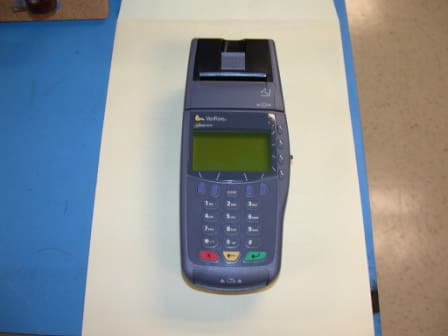
Click to zoom
Application Details
- Equipment Class
- TNB - Licensed Non-Broadcast Station Transmitter
- Date of Grant
- Aug 03, 2003
- Application Purpose
- Original Equipment
- Date of Application
- Aug 03, 2003
- Equipment Note
- Wireless Point of Sale Terminal
- Frequency Range
- 824.73000000 - 848.19000000
- Company
- VeriFone Inc
- Country
- United States
Documents & Files
Document Text
Text extracted from the exhibit documents filed with the FCC. Open a document above to read the original.
Users Manual
VeriFone Inc. 3755 Atherton Road Rocklin, CA 95765-3701 Tel: 916/630-0550 Fax: 916/630-2501 Date: July 7, 2003 Federal Communication Commission Office of Engineering Technology Equipment Authorization Division Subject: User Manual Illustrations To Whom It May Concern: The Omni 3600C Wireless Handheld Point of Sale Terminal user manual initialed “Omni 3600 Installation Guide” VeriFone part number VDN 22060 is used with many of VeriFone’s wireless products. The illustration on the cover represents VeriFone’s first wireless product and is not meant to be used for identification purposes in the current type submittal. The associated photographs and module number are meant for this purpose. Sincerely, Technical Staff Senior EMC Engineer William Morse NCE Phone 916.630.2540 FAX 916.630.2501 EMAIL [email protected]
Users Manual
2003 VeriFone , Inc. All ri g hts reserved. VeriFone, Inc. 2455 Augustine Drive Santa Clara CA 95054-3002 Tel: 800-VeriFone (837-4366) www.verifone.com Omni 3600 Certifications and RegulationsVeriFone Part Number: 22475 Revision D Omni 3600 Certifications and Regulations FCC ComplianceManufacturer: VeriFone, Inc.Model: Omni 3600FCC Part 15 Class BThis device complies with Part 15 of the FCC Rules. Operation is subject to the following two conditions: (1) this device ma y not cause harmful interference, and (2) this device must accept any interference received, including interference that may cause undesired operation. SAR LabelingMobitexUSATo comply with the FCC RF exposure requirements, bystanders and parts of the users body other then the extremities must be at least 15.0mm away from the device.CDMAUSATo comply with the FCC RF exposure requirements, bystanders and parts of the users body other then the extremities must be at least 15.0mm away from the device. SAR compliance for body-worn operations is restricted to belt-clips, holsters, or similar accessories that have no metallic component in the assembly.Brazil"""O terminal Omni 3600 atende aos limites da Taxa de Absorção Es pecífica referente à exposição a campos elécticos, magnéticos e electromagnéticos de radiofreqüências adoptados pela Anatel.""" GSM/GPRSUSAThis device is reported as fully compliant with Body Worn configuration using accessories that contain no metal. ElectricalLI-ion Battery Module—Rechargeable Battery Unit CautionDo not:• disassemble, crush, puncture, or incinerate in fire. • short circuit contacts. • expose to temperatures exceeding 140 ° F (60 ° C). Power PacksBefore you connect the terminal power pack to an electrical outlet, check that the on/off power switch on the terminal is off . If the terminal does not have an on/off switch, check that the power cable connector is removed from the terminal’s power port. or When connecting the terminal to a power pack, always connect the three-pronged plug of the power pack to an electrical wall outlet first . Then connect the power cable to the terminal’s power port. AC AdapterThe AC adapter is designed to ensure your personal safety and to be compatible with this equipment. Please follow these guidelines:• Do not use the adapter in a high moisture environment. Never touch the adapter when your hands or feet are wet. • Allow adequate ventilation around the adapter. Avoid locations with restricted airflow. • Connect the adapter to a proper power source. The voltage and grounding requirements are found on the product case and/or packaging. • Do not use the adapter if the cord becomes damaged. • Do not attempt to service the adapter. There are no serviceable parts inside. Replace the unit if it is damaged or exposed to excess moisture. Separate Power SourcesSome peripherals require a separate power source. Before connecting a check reader or similar device, turn off power to the terminal. PeripheralsBefore connecting any peripheral device, turn off power to the terminal. Turn on power only after you are finished connecting the peripheral device(s). For complete information about peripheral installation and use, please refer to the user documentation supplied with those devices. Disconnecting PowerDisconnecting power during a transaction may cause transaction data files that are not yet stored in terminal memory to be lost. Surge ProtectorsTo protect your terminal against possible damage caused by lightni ng strikes and electrical surges, you may want to install a p ower surge protector. Location – Electrical ConsiderationsCAUTION: Due to risk of electrical shock or terminal damage, do not use the terminal near water, including a bathtub, wash bowl, kitchen sink or laundry tub, in a wet basement, or near a swim ming pool. Also, avoid using this product during electrical storm s. Avoid locations near electrical appliances or other devices that cause excessive voltage fluctuations or emit electrical noise (for example, air conditioners, neon signs, high-frequency or magnetic security devices, or electric motors). EquipmentDamageCarefully inspect the shipping carton and its contents for any damage. If the terminal or any product component appears damaged or tampered with, immediately notify the shipping company and your VeriFone distributor or service provider.CAUTION : Do not use a terminal that has been damaged or tampered with. RepairsUnless otherwise instructed in this document, do not, under any circumstances , attempt any service, adjustments, or repairs on this equipment. Instead, contact your local VeriFone distributor or service provider for assistance. Failure to comply may invalidat e the product warranty. Location – Environmental ConsiderationsDo not plug the power pack into an outdoor outlet or operate the terminal outdoors. It is not waterproof or dustproof, and is f or indoor use only. Any damage to the unit from exposure to rain or dust may void your warranty.Do not use the terminal where there is high heat, dust, humidity, moisture, or caustic chemicals or oils. Keep the terminal awa y from direct sunlight and anything that radiates heat, such as a stove or a motor. Cleaners and SolventsNever use thinner, trichloroethylene, or ketone-based solvents to clean the terminal — they may deteriorate plastic or rubber p arts. Do not spray cleaners or other solutions directly onto the keypad or display. For best results, use a VeriFone Cleaning Kit or a clean cloth dampened with water and mild soap. To remove stubborn stains, use alcohol or an alcohol-based cleaner. Location – Ease of UseSelect a location for your terminal that contributes to its ease of use:• A location convenient for both merchant and cardholder. • A flat support surface, such as a countertop or table. • A location near a power outlet and a telephone/modem line connection. WARNING! Changes or modifications to this unit not expressly appr oved by the party responsible for compliance could void the…
Text truncated - open the document above for the full version.
Users Manual
Part Number 22060, Revision D VERIX OPERATING ENVIRONMENT SOFTPAY E-PAYMENT APPLICATION VERIX DEVELOPMENT TOOLS DEVELOPER TOOLKIT VERISHIELD SECURITY ARCHITECTURE OMNI 33XX MULTI-APPLICATION APPLIANCES VERICENTRE APPLIANCE MANAGEMENT SUITE RADIO MODEM OMNI 3600 APPLIANCES HAND-HELD OMNI 37XX HAND-OVER-COUNTER MULTI-APPLICATION APPLIANCES Omni 3600 Installation Guide All rights reserved. No part of the contents of this document may be reproduced or transmitted in any form without the written permission of VeriFone, Inc. The information contained in this document is subject to change without notice. Although VeriFone has attempted to ensure the accuracy of the contents of this document, this document may include errors or omissions. The examples and sample programs are for illustration only and may not be suited for your purpose. You should verify the applicability of any example or sample program before placing the software into productive use. This document, including without limitation the examples and software programs, is supplied “As-Is.” VeriFone, Inc. 2455 Augustine Drive Santa Clara CA 95054-3002 www.verifone.com Part Number 22060, Revision D Omni 3600 Installation Guide © 2003 VeriFone, Inc. VeriFone, the VeriFone logo, Omni, VeriCentre, Verix, and ZonTalk are registered trademarks of VeriFone. Other brand names or trademarks associated with VeriFone’s products and services are trademarks of VeriFone, Inc. All other brand names and trademarks appearing in this manual are the property of their respective holders. Comments? Please e-mail all comments in this document to [email protected] WARNING Do not dispose of the Li-ion smart battery in a fire. Li-ion batteries must be recycled or disposed of properly. Do not dispose of Li-ion batteries in municipal waste sites. OMNI3600 INSTALLATION GUIDE3 CONTENTS CHAPTER1 IntroductionSelect a Location . . . . . . . . . . . . . . . . . . . . . . . . . . . . . . . . . . . . . . . . . . . . . . . . . 7 Omni 3600 Terminal . . . . . . . . . . . . . . . . . . . . . . . . . . . . . . . . . . . . . . . . . . . . 7 Omni 3600 Base . . . . . . . . . . . . . . . . . . . . . . . . . . . . . . . . . . . . . . . . . . . . . . . 7 Environment . . . . . . . . . . . . . . . . . . . . . . . . . . . . . . . . . . . . . . . . . . . . . . . . . . 7 Convenience . . . . . . . . . . . . . . . . . . . . . . . . . . . . . . . . . . . . . . . . . . . . . . . . . . 8 Safety Concerns . . . . . . . . . . . . . . . . . . . . . . . . . . . . . . . . . . . . . . . . . . . . . . . 8 CHAPTER2 Omni 3600 Terminal Unpack the Shipping Carton. . . . . . . . . . . . . . . . . . . . . . . . . . . . . . . . . . . . . . . . . 9 Terminal Features . . . . . . . . . . . . . . . . . . . . . . . . . . . . . . . . . . . . . . . . . . . . . . . 10 Power Port . . . . . . . . . . . . . . . . . . . . . . . . . . . . . . . . . . . . . . . . . . . . . . . . . . 11 Smart Battery . . . . . . . . . . . . . . . . . . . . . . . . . . . . . . . . . . . . . . . . . . . . . . . . . . . 11 Smart Battery Installation . . . . . . . . . . . . . . . . . . . . . . . . . . . . . . . . . . . . . . . 12 Smart Battery Removal. . . . . . . . . . . . . . . . . . . . . . . . . . . . . . . . . . . . . . . . . 13 Smart Battery Charging . . . . . . . . . . . . . . . . . . . . . . . . . . . . . . . . . . . . . . . . 13 Smart Battery Life . . . . . . . . . . . . . . . . . . . . . . . . . . . . . . . . . . . . . . . . . . . . . 14 Turn On/Off the Omni 3600 Terminal . . . . . . . . . . . . . . . . . . . . . . . . . . . . . . . . . 14 Paper Installation . . . . . . . . . . . . . . . . . . . . . . . . . . . . . . . . . . . . . . . . . . . . . . . . 14 Printer Test . . . . . . . . . . . . . . . . . . . . . . . . . . . . . . . . . . . . . . . . . . . . . . . . . . 16 Install/Replace MSAM Cards . . . . . . . . . . . . . . . . . . . . . . . . . . . . . . . . . . . . . . . 16 Install/Replace SIM Card (GSM models) . . . . . . . . . . . . . . . . . . . . . . . . . . . . . . 18 Wireless Transactions . . . . . . . . . . . . . . . . . . . . . . . . . . . . . . . . . . . . . . . . . . . . 20 Smart Card Reader Transactions. . . . . . . . . . . . . . . . . . . . . . . . . . . . . . . . . . . . 20 Magnetic Card Reader Transactions . . . . . . . . . . . . . . . . . . . . . . . . . . . . . . . . . 20 Antenna (Some Wireless Models) . . . . . . . . . . . . . . . . . . . . . . . . . . . . . . . . . . . 21 Installation. . . . . . . . . . . . . . . . . . . . . . . . . . . . . . . . . . . . . . . . . . . . . . . . . . . 21 Orientation . . . . . . . . . . . . . . . . . . . . . . . . . . . . . . . . . . . . . . . . . . . . . . . . . . 21 Replace the Antenna . . . . . . . . . . . . . . . . . . . . . . . . . . . . . . . . . . . . . . . . . . 22 CHAPTER3 Omni 3600 BaseUnpack the Shipping Carton. . . . . . . . . . . . . . . . . . . . . . . . . . . . . . . . . . . . . . . . 23 Omni 3600 Base Features . . . . . . . . . . . . . . . . . . . . . . . . . . . . . . . . . . . . . . . . . 24 Power Connection . . . . . . . . . . . . . . . . . . . . . . . . . . . . . . . . . . . . . . . . . . . . . . . 26 Omni 3600 Terminal Docking . . . . . . . . . . . . . . . . . . . . . . . . . . . . . . . . . . . . . . . 27 Spare Smart Battery Pack . . . . . . . . . . . . . . . . . . . . . . . . . . . . . . . . . . . . . . . . . 27 Omni 3600 Base Communications Ports . . . . . . . . . . . . . . . . . . . . . . . . . . . . . . 28 Telephone Line Ports . . . . . . . . . . . . . . . . . . . . . . . . . . . . . . . . . . . . . . . . . . 28 Telephone Line Connections . . . . . . . . . . . . . . . . . . . . . . . . . . . . . . . . . . . . 29 Peripheral Devices . . . . . . . . . . . . . . . . . . . . . . . . . . . . . . . . . . . . . . . . . . . . . . . 29 Optional Peripheral Device Port . . . . . . . . . . . . . . . . . . . . . . . . . . . . . . . . . . 29 Check Readers Supported . . . . . . . . . . . . . . . . . . . . . . . . . . . . . . . . . . . . . . 30 External Printers S…
Text truncated - open the document above for the full version.
Users Manual
OMNI3600 TERMINAL Install/Replace MSAM Cards 16OMNI3600 INSTALLATION GUIDE Figure 8Close the Printer Cover Printer Test To ensure the printer is operating correctly: 1Turn on the terminal by pressing the green enter key (see Figure 2, page 10). 2Enter system mode by pressing F2+F4 at the initial copyright screen, and entering the system mode password (see Passwords). 3Toggle through the SYS MODE MENU screens, using the down arrow key until you reach SYS MODE MENU 6. 4Press F4 to enter the Printer ID screen. 5Press F3, Test, to start the printer self-test. The test printout, with printer information and repeating character strings, is approximately 38 cm (15 in.) long. Install/Replace MSAM Cards When you first receive your Omni 3600 terminal, you may need to install a merchant smart card or one or more micromodule-sized security account manager (MSAM) cards, or you may need to replace old cards. Often, these small cards arrive on a larger, credit card-style plastic card, from which they must be removed. The following procedure describes MSAM card installation. 1Remove the battery (see Smart Battery) 2Open the MSAM door located beneath the battery (Figure 9): aPush down and back on the raised arrow on the door. bLift up on the raised arrow with the tip of your index finger. NOTE To prevent damage to the print roller on the paper roll cover, always close the cover by gently pressing down on the paper roll cover tab. CAUTION Observe standard precautions for handling electrostatically sensitive devices. Electrostatic discharges can damage this equipment. An anti-static wrist strap grounded to a metal surface is recommended. OMNI3600 TERMINAL Install/Replace MSAM Cards O MNI3600 INSTALLATION GUIDE17 cOpen the door until it is in the upright position, resting against the end of the terminal. Figure 9Open the MSAM Access Door The three MSAM cardholders are now accessible. Each cardholder consists of a hinged tilt-up cover attached to a connector base (Figure 10). Figure 10MSAM Card Installation 3Access the MSAM cardholders (reference Figure 10): aUnlock the cardholder: Slide the lock plate to the unlocked position, in the OPEN direction (Figure 11). Figure 11MSAM Cardholder Lock Plate Detail OMNI3600 TERMINAL Install/Replace SIM Card (GSM models) 18OMNI3600 INSTALLATION GUIDE bOpen the cardholder by pivoting the cover on its hinge away from the connector base (Figure 12). Figure 12Insert MSAM Card into Cardholder 4Remove any previously installed MSAM card by sliding the card from the cover. 5Install an MSAM card by aligning the card and carefully sliding it within the guides on the cover until fully inserted. 6Close the cover (Figure 12). 7Lock each MSAM cardholder by sliding its locking plate towards the LOCK arrow until the plate stops (Figure 11). 8Close the MSAM door. 9Replace the smart battery. Install/Replace SIM Card (GSM models) The SIM (Subscriber Identity Module) card is a smart card inserted in the Omni 3600 GSM terminal that contains your GSM radio account information. Use the following procedure to replace or install a SIM card. NOTE The cardholder has a set of contacts and a notch on one corner to ensure the MSAM card is positioned correctly when the cover is closed. The MSAM card has a notch on one corner to ensure it is correctly positioned in the cardholder. Before inserting the MSAM card, position it as shown in Figure 12. CAUTION To avoid damage to the MSAM cardholders, ensure each cardholder is locked before closing the MSAM door. OMNI3600 TERMINAL Install/Replace SIM Card (GSM models) O MNI3600 INSTALLATION GUIDE19 1Remove screw from SIM card access door on back of Omni 3600 terminal (Figure 13). Figure 13Remove SIM Door Screw 2Remove the SIM card access door (Figure 14): Figure 14Slide Off SIM Card Access Door 3Open the SIM card holder and slide the SIM card supplied by your provider into the cardholder (Figure 15). Figure 15Insert SIM Card into Cardholder 4Replace the SIM card access door and screw. NOTE Do not lose the SIM card dust cover or retaining screw. NOTE The SIM cardholder has a notch on one corner to ensure the SIM card is positioned correctly. The SIM card has a notch on one corner for easy orientation in the cardholder. Before inserting the SIM card, position it as shown in Figure 15, with the card’s gold contacts facing down. OMNI3600 TERMINAL Wireless Transactions 20OMNI3600 INSTALLATION GUIDE Wireless Transactions To conduct a wireless transaction: •Ensure the terminal is in an optimal position for transmitting. •Follow the on-screen instructions provided with your application. Smart Card Reader Transactions To conduct a smart card transaction: 1Position the smart card with the contacts up and insert it into the smart card reader slot in a smooth, continuous motion until it seats firmly (Figure 16). Leave the smart card in the card reader until the transaction is complete. Premature removal voids the transaction. Figure 16Using the Primary Smart Card Reader 2Remove the card when the display indicates the transaction is complete. Magnetic Card Reader Transactions To conduct a credit/debit card transaction: 1Position the card with the magnetic stripe facing down and towards the printer. 2Swipe it through the reader from left-to-right, as shown in Figure 17. Figure 17Using the Magnetic Card Reader OMNI3600 TERMINAL Antenna (Some Wireless Models) O MNI3600 INSTALLATION GUIDE21 Antenna (Some Wireless Models) For some Omni 3600 terminals to establish a wireless connection, an external antenna is provided. This connection allows communication with your service provider to upload transaction data from the terminal and download system upgrades to the terminal. Radio service is activated by your service provider. Data transfers can also be performed through the Omni 3600 base (see Omni 3600 Base Communications Ports). This section only discusses Omni 3600 terminals with external antenna. Installation The Omni 3600 should arrive from manufacture with the antenna attac…
Text truncated - open the document above for the full version.
Cover Letter(s)
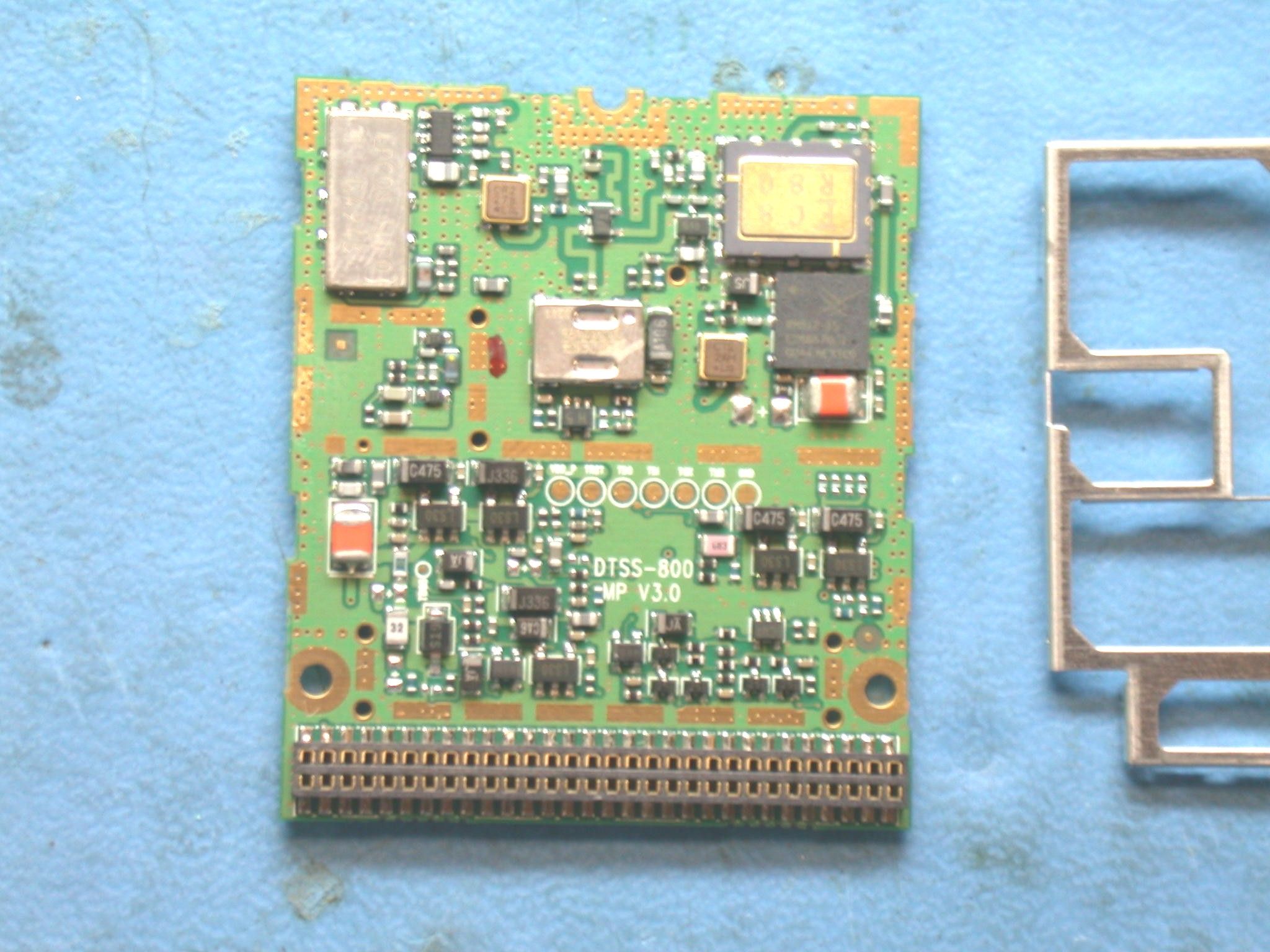
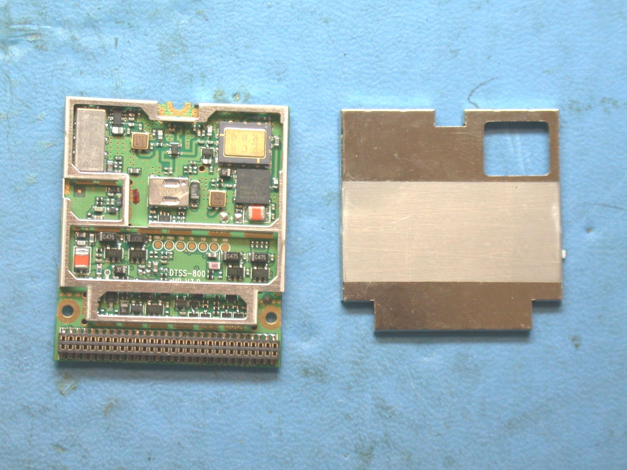
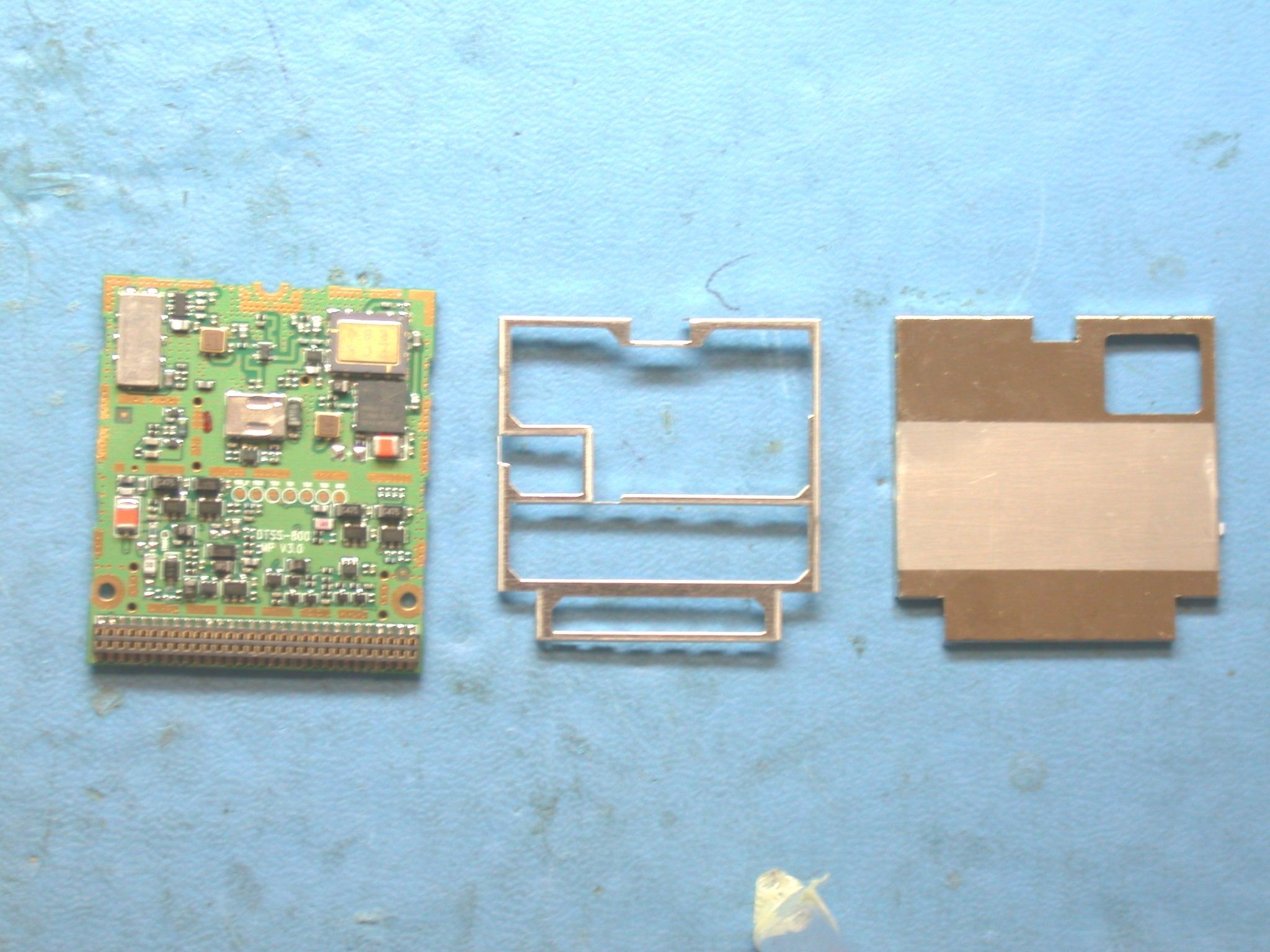
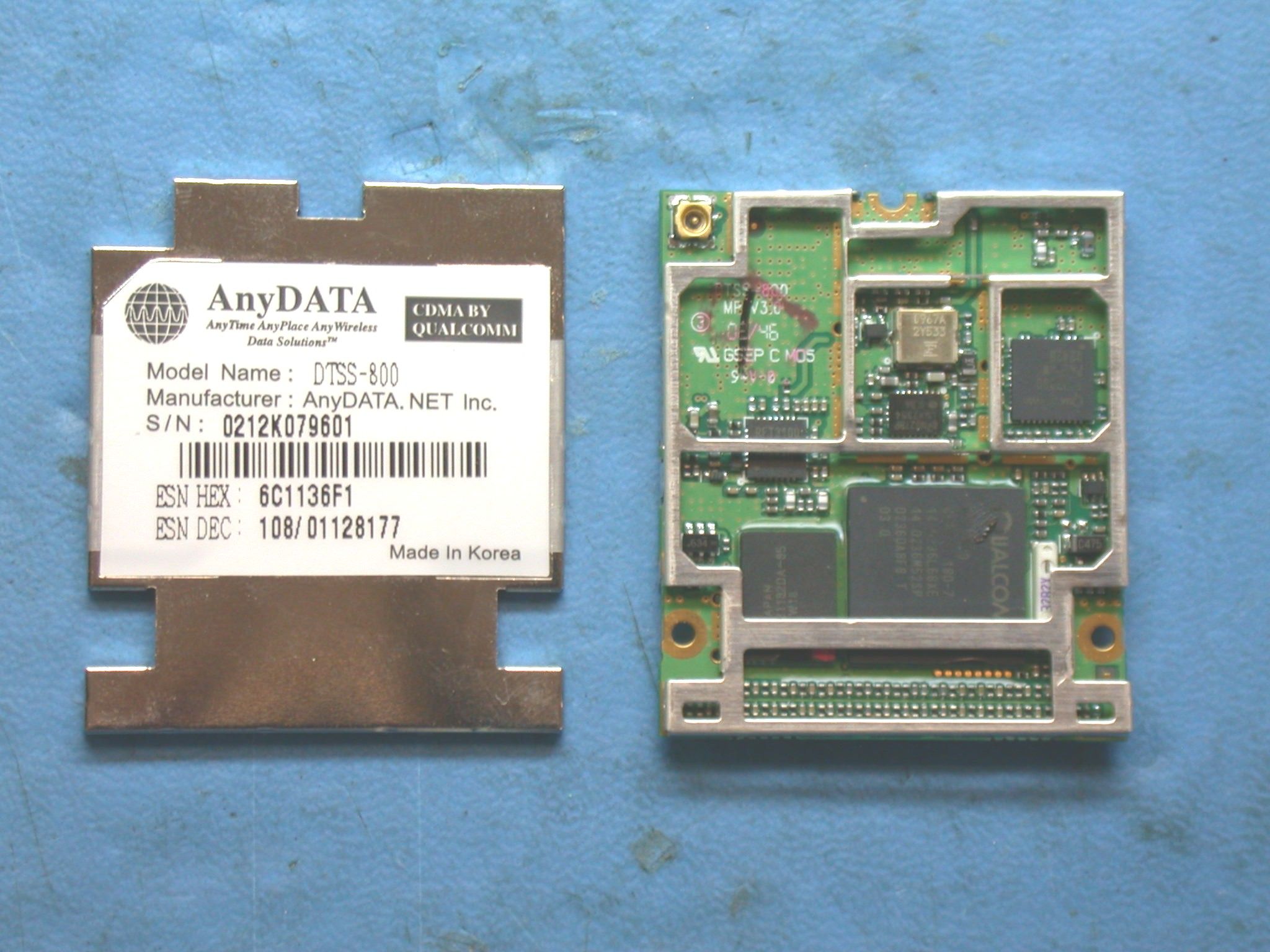
VeriFone Inc. 3755 Atherton Road Rocklin, CA 95765-3701 Tel: 916/630-0550 Fax: 916/630-2501 Date: July 7, 2003 Federal Communication Commission Office of Engineering Technology Equipment Authorization Division Subject: Product Contains an FCC Approved Radio Modem To Whom It May Concern: The Omni 3600C Wireless Handheld Point of Sale Terminal incorporates an RF module transmitting in the frequency range of 824 - 849MHz that received previous certification under FCC ID: P4M-DTSS_800. The radio is not modified or adjusted in VeriFone’s manufacturing process from the condition sent from the radio’s original manufacture. Sincerely, Technical Staff Senior EMC Engineer William Morse NCE Phone 916.630.2540 FAX 916.630.2501 EMAIL [email protected]
Cover Letter(s)
VeriFone Inc. 3755 Atherton Road Rocklin, CA 95765-3701 Tel: 916/630-0550 Fax: 916/630-2501 Date: May 19, 2003 Federal Communication Commission Office of Engineering Technology Equipment Authorization Division Subject: Application for Equipment Authorization, FCC ID: B32OMNI3600C To Whom It May Concern: Pursuant to section 0.459 of 47 CFR, confidentiality is requested for: schematics , block diagram and the theory of operation. Justification for this request is the protection of proprietary trade secrets and that such materials would customarily be guarded from competitors. Fees for the requested confidentiality has been paid as a part of the overall remittance. Sincerely, Technical Staff Senior EMC Engineer William Morse NCE Phone 916.630.2540 FAX 916.630.2501 EMAIL [email protected]
External Photos
VeriFone Inc. FCC ID: B32OMNI3600C EXHIBIT C - EUT PHOTOGRAPHS Chassis - Top View Chassis - Back View VeriFone Inc. FCC ID: B32OMNI3600C Chassis – Right Side View
ID Label/Location Info
EXHIBIT A - FCC ID LABELING AND WARNING STATEMENT Proposed FCC ID Label Specifications: Text is black or white in color and is left justified. Labels are silk-screened and shall be “permanently affixed” at a conspicuous location on the EUT. Proposed Label Location on EUT Back Side of the EUT/Proposed ID Label Location FCC Warning Statement A FCC Warning Statement is provided in the product manual. FCC ID: B32OMNI3600C
Internal Photos
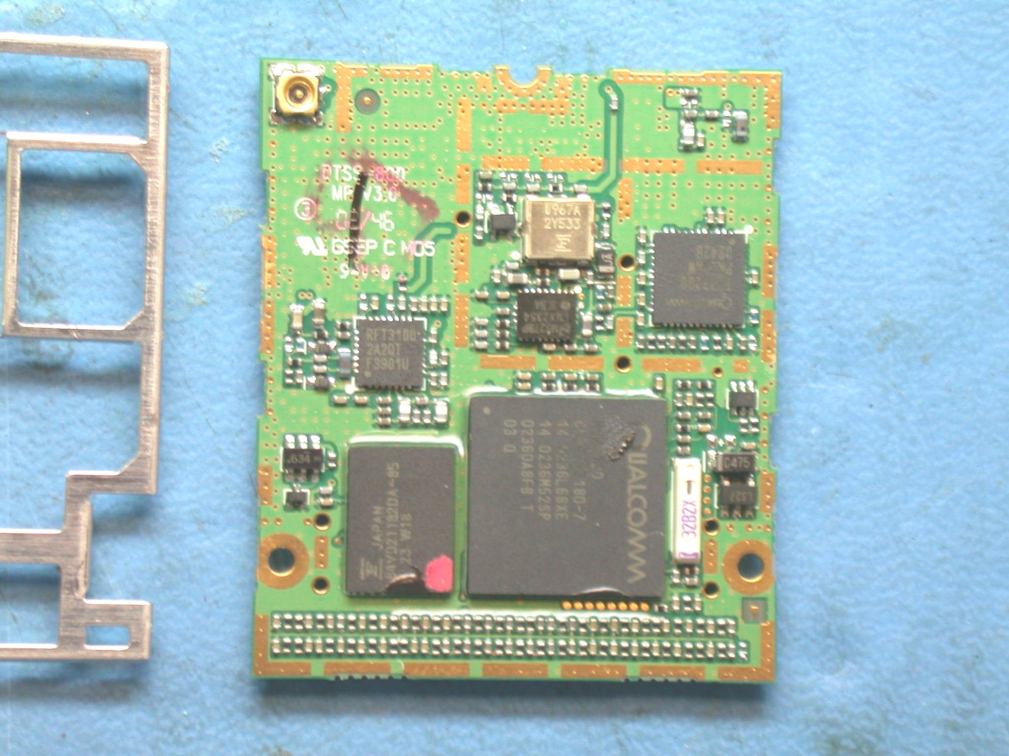
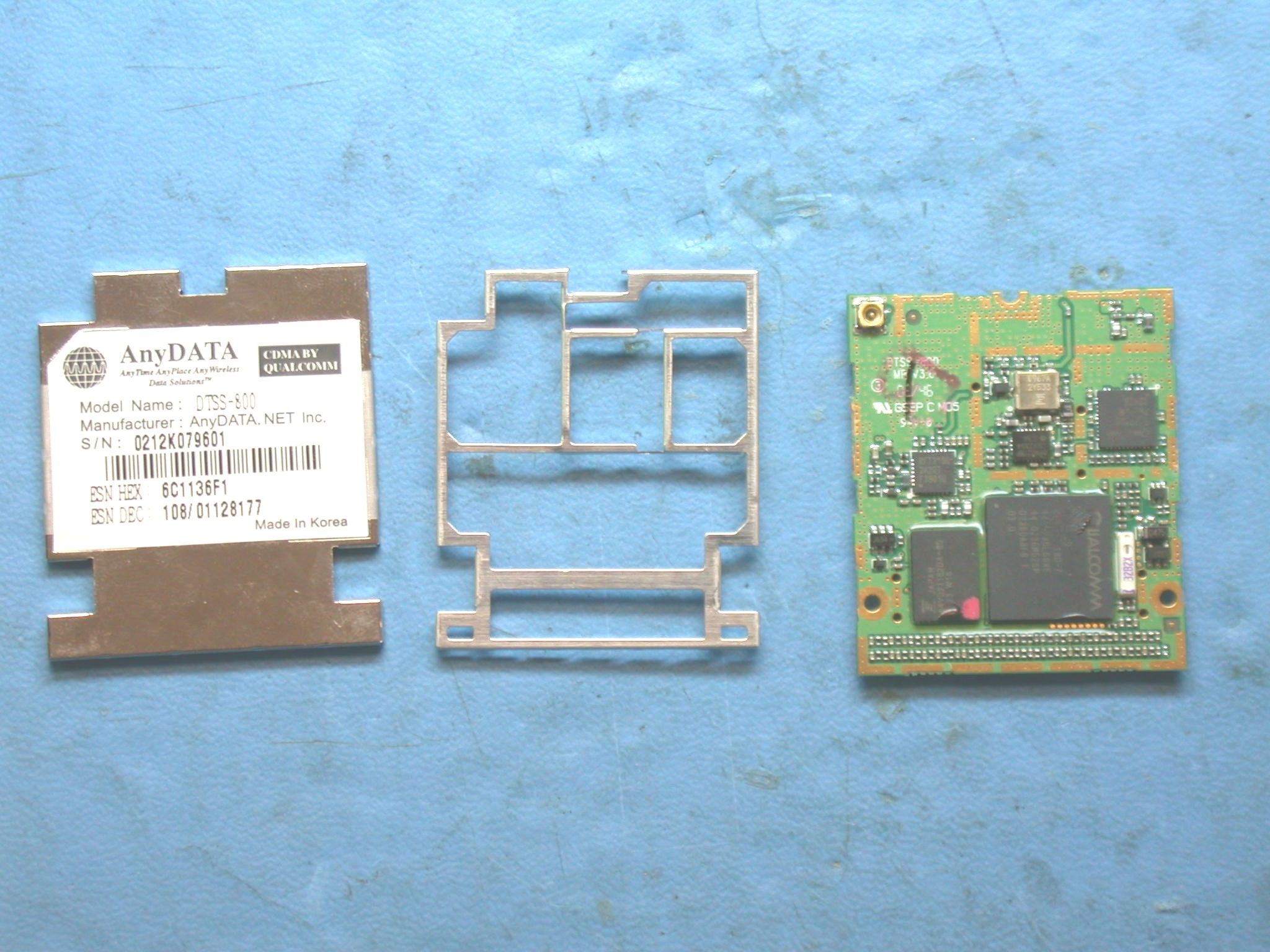
VeriFone Inc. FCC ID: B32OMNI3600C Chassis – Cover off View EUT – Inside Explode View VeriFone Inc. FCC ID: B32OMNI3600C EUT – Antenna and Modem View EUT – Antenna and Modem View 2 VeriFone Inc. FCC ID: B32OMNI3600C EUT – AnyData Modem and Antenna View EUT – AnyData Modem Close Up View VeriFone Inc. FCC ID: B32OMNI3600C EUT – SN7 Close Up View
Parts List/Tune Up Info
Agile Software Part P096-100-17 [OMNI 3600,2MF/1M SAM/DC/CDMA IPP7] Production Title Block Oracle BOM OrgsDescription KHH, LCNOMNI 3600, 2MF/1M SAM/DC/CDMA IPP7 Part TypeOracle Template PartFinished Good Rev Release DateRev Incorp DateAccessItem NumberRevision 01-May-2003 18:49:29 P096-100-17C Page Two CM Lead-Time CM Std Cost Critical Safety Comp No EOL Support Ends Notes AMR BOM for Lightning CDMA 800MHz P-Level NPI Pricing Owner's Site SMF Product Code (4 Char Req'd) 00SB Security Code - Serialized Yes Taxware Code 9A005 HARDWARE - Sale Unit Of Measure EA VFI Std Cost Changes (Pending Changes) TypeECO NumberProposed RevStatusDescription Changes (Change History) Rev Lifecycle Phase Release Date Obsolete Date Type ECO Number Description CProduction01-May- 2003 18:49:29 ECO- Std C08494Use MRD531B for three track product that use MRD530A originally. BProduction21-Mar- 2003 08:53:10 ECO- Std C0886218372-02 O3600 system PCBA will be replaced with 18448-02. 18372-02 PCBA and its corresponding PCB 18373-01 will be end of life'd (per MCO C01258)- the inventory is to be used up till gone. Please cancel all of the outstanding POs. AProduction14-Mar- 2003 17:18:15 ECO- Std C08861Implementation of IPP7 on O3600 platform. 18372-01 PCBA rolls to 18372-02. All P- levels & M-levels will have the prefix changed as follows P096-xxx-0x to P096- xxx-1x & M096-xxx-0x-CC1 to M096-xxx-1x- CC1. Releasing only currently forecasted Offline (-04) and GSM/GPRS M-levels for now at numeric rev for forecasting. Obsoleting the old numeric GSM/GPS -05 & -06 M-levels. This rolls affects: 1) IPP7 chip on 18372; note this does not apply to P096- 100-x5 & P096-100-x6 which use 18448-01 PCBA already with IPP7 2) MIB block part number change due to mandatory P-level number change and 3) Product & unit labels - new P-level part number. Cleaned up M-level drawings and assigned new part numbers compatible with IPP7 and upcoming EMV4.0 part number changes. BOM Revision C Effective from 30-Apr-2003 00:00:00 to LevelFind #Item NumberPart DescriptionRevQtyUMRef Des Notes Lifecycle Phase 0 P096-100-17OMNI 3600, 2MF/1M SAM/DC/CDMA IPP7 C 10PX96-100-XX-APROD DWG OMNI 3600 HANDHELD A0EA Production 11096-100-17UNIT, O3600 2MF/1M SAM/DC/CDMA IPP7 C1EA Production 2021955-01INST MFG BLOCK O3600 A0EA Production 2021956-17INFO MFG BLOCK O3600 CDMA A0EA Production 20X96-100-XX-AUNIT DWG OMNI 3600 2MF/1M SAM A0EA Production 2122033-01CHASSIS HH O3600C1EA Production 2222050-01ASSY TOP CASE HH O3600 D1EA Production 3022050-01-FARTWORK TOP CASE HH O3600 B0EA Production 3022050-XXASSY DWG TOP CASE HH O3600 D0EA Production 3122034-01CASE TOP HH O3600D1EA Production 3204385-01BAR PAPER TEAR PRINTPAK 300 D1EA Production 2422036-01DOOR GSM BTM CASE HH O3600 A1EA Production 2522035-04CASE BTM GSM/GPRS INT ANT O3600 B1EA Production 2622038-01DOOR SAM BTM CASE HH O3600 A1EA Production 2722039-01KEYPAD MAIN HH O3600 A1EA Production 2822040-01KEYPAD ATM HH O3600A1EA Production 2922056-01ASSY PRINTER DOOR HH O3600 A1EA Production 3022056-XXASSY DWG PRINTER DOOR HH O3600 A0EA Production 3122041-01DOOR PRINTER HH O3600 A1.000EA Production 3222047-01LATCH PRINTER DOOR HH O3600 A1.000EA Production 21022376-01PRINTER MECH APS THERMAL 7.2V ESD A1EA Production 21119333-01ASSY, MG-HD/HD/FPCB 3TK EVEREST PLUS A1EA Production 3019333-XX-AASSY DWG, MH/HD/FPCB 3T EVEREST PLUS A0EA Production 3119353-01ASSY MAG-HD/HLDR 3- TK EVEREST PLUS A1EA Production 41HMGH0011MAGNETIC HEAD 3 TRK READ W/GND-TAB B1EA Production 4205679-01HOLD MAG HD MSR300A1EA Production 3219335-01FPCB MAG-HD 3-TRACK EVEREST PLUS B1EA Production 21205678-01PLATE MAG HD MSR300B1EA Production 21422044-02ASSY, BATTERY 7.2V/2000MAH O36XX HH A1EA Production 21514101-01FOOT RUBBER 15.3LX3.2WX3.4H A2EA Production 21614881-03LCM 128X64 DOT MTRX STN TRANSFLECT A1EA Production 21722051-01BEZEL LCD/BACKLIGHT HH O3600 A1EA Production 21919343-01ASSY SHELL PED FENCE A1EA Production 3019343-XX-AASSY DWG SHELL PED FENCE C0EA Production 3119344-01SHELL EVEREST PLUSC1EA Production 3219345-01FILM CIRCUIT EVEREST PLUS B1EA Production 3319346-01ZEBRA STRIP FILM EVEREST PLUS B1EA Production 3419347-01ZEBRA STRIP CONNECTOR EVEREST PLUS B1EA Production 22022732-01CDMA RADIO ADAPTER MODULE B1EA Production 3022732-01-AASSY DWG CDMA RADIO ADAPTER MODULE B0EA Production 3118478-01PCB ASSY O3600 B1EA Production RADIO CDMA ADAPTER 4018478-XX-APCBA DWG O3600 RADIO CDMA ADAPTER A0EA Production 4018478-XX-SSCHEM O3600 RADIO CDMA ADAPTER B0EA Production 4118479-01PCB O3600 RADIO CDMA ADAPTER A1EA Production 42CCA475Z3NY1CAP SMT 4.7UF 16V Y5V C1206 F1EAC1 Production 43CCA104K3NX7CAP SMT 100NF 10% 16V X7R 0603 F1EAC2 Production 44CCA106M1QACAP SMT 10MF 20% 6.3V TANT 3216 A1EAC3 Production 45CCA227M2QCAP, SMT 220MF 20% 10V LOW ESR 7343H A1EAC4 Production 47CCN04024HMCONN, SMT 4PIN RIGHT ANGLE PCB MOUNT A1EAP1 Production 48CCN60015HMCONN SMT 2X30 HEADER A1EAP2 Production 49CCN30012RMCONN, SMT 1X30 .5MM PITCH ZIF FPC RA A1EAP3 Production 410CRS2373BB0MRES SMT 237K OHM 1/10W 1% 0603 A1EAR1 Production 411CRS1003BB0MRES SMT 100K OHM 1/10W 1% 0603 B1EAR2 Production 412CRS000BJ0MRES SMT 00 OHM JUMPER 1AMP 0603 A6EAR3-R8removed R9 R10 and added R4 and R7 Production 414CVR04ADE01MIC, SMT VR ADJ 2.5VDC 1.5A TO263-5 A1EAU1 Production 420CCN02040ACONN, CDMA BRD MNT ANT SOCKET A1EAP4NOTE: this needs to be pushed back as far away from the radio as is possible to minimize the likelihood of contact. Production 3222753-01RADIO MODEM, CDMA 800 MHZ A1EA Production 3322729-01FLEX CABLE OMNI 3600 CDMA A1EA Production 34HMSP02CTMSCREW MACH M2X0.4PX8L PAN STL ZN A3EA Production 3517282-01ADH, THEADLOCKER LOCTITE 262 10ML A0.0030EA Apply to three screws after nuts finger Production tightened 36HST8COS00SPACER 4.75ODX2.92IDX3.18L STEEL A1EA Production 3722751-01ANTENNA ASSY CDMA 800MHZ A1EA Production 38HNTA205F1NUT M2 X 0.4 PA3EA Production 39HHMAG0001ADHESIVE GLUE HEAT MELT A1.5GM Production 22322149-01ASSY LENS W/LOGO HH O3600 A1EA Production 3022149-XXASSY…
Text truncated - open the document above for the full version.
Parts List/Tune Up Info
Tune up procedure To set up transmit power before shipping, AnyDATA uses a manufacturing process which is called “Calibration of Rx and Tx power over the dynamic range, temperature and frequency”. CDMA technical standard requires AnyDATA’s CDMA module to transmit more than +23dBm output power when it is required to transmit its maximum power. Therefore, AnyDATA sets the maximum power of the module to +24dBm (+/-) 1dB. By adjusting Tx AGC Amplifier built in the CDMA module, transmit power can be limited to +24dBm (+/-) 1dB. Transmit power calibration consists of transmit linearizer calibration, and power compensation calibration over the temperature and frequency. During the transmit linearizer calibration, the module searches for 16 AGC adjust values for the 16 power levels within the dynamic range including the maximum output power and saves these AGC adjust values in the memory device in the module. These searched AGC adjust values (TX_LIN_MASTER) set the maximum power of the module. To prevent the variation in maximum power over the frequency, the transmit circuit is calibrated over the frequency and compensation values (TX_LIM_VS_FREQ) are found. These values are also used to limit the maximum output power to +24dBm (+/-)1dB. Also to prevent the variation in maximum power over the temperature, the transmit circuit is calibrated over the temperature and compensation values (TX_LIM_VS_TEMP) are found. These are also used to limit the maximum output power to +24dBm (+/-)1dB when there is a variation in temperature..
RF Exposure Info
Note: This test report is specially limited to the above client company and the product model only. It may not be duplicated without prior written consent of Bay Area Compliance Laboratory Corporation. This report must not be used by the client to claim product endorsement by NVLAP or any agency of the U.S. Government. SAR EVALUATION REPORT For VeriFone Inc. 3755 Atherton Road Rocklin, CA 95765 FCC ID: B32OMNI3600C 2003-07-17 This Report Concerns: Original Report Equipment Type: Wireless Point of Sale Terminal Test Engineer:Eric Hong Report No.:R0305222S Test Date:2003-04-16 Reviewed By:Hans Mellberg Prepared By:Bay Area Compliance Laboratory Corporation 230 Commercial Street Sunnyvale, CA 94085 Tel: (408) 732-9162 Fax: (408) 732 9164 VeriFone Inc. FCC ID: B32OMNI3600C Report #R0305222S SAR Evaluation Report Page 2 of 46 TABLE OF CONTENTS SUMMARY........................................................................................................................................................................................3 1 - REFERENCE......................................................................................................…
Text truncated - open the document above for the full version.
Contact Information
Applicant
Kenji Chao(Sr. Director, Hardware Engineering)
Test Firm
Bay Area Compliance LaboratoryJohn Chan
Technical Specifications
| # | Rule Parts | Frequency Range | Power Output | Emission | Tolerance |
|---|---|---|---|---|---|
| 1 | 22H | 824.73 MHz - 848.19 MHz | 369.00 mW | 1M25F9W | 2.5000000000 ppm |
Other Applications from VeriFone Inc
B32VS100P
Jun 22, 2026Point of Sale Terminal
Equipment Class
DXX - Part 15 Low Power Communication Device Transmitter
B32V660CA2
Apr 20, 2026Point of Sale Terminal
Equipment Class
NII - Unlicensed National Information Infrastructure TX
B32VM110R
Mar 31, 2026Point of Sale Terminal
Equipment Class
PCB - PCS Licensed Transmitter
B32VN100
Feb 02, 2026Point of Sale Terminal
Equipment Class
DXX - Part 15 Low Power Communication Device Transmitter
B32VS100M
Dec 03, 2025Point of Sale Terminal
Equipment Class
PCE - PCS Licensed Transmitter held to ear