B32OMNI3600GPoint of Sale Terminal
VeriFone Inc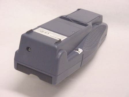
Click to zoom
Application Details
- Equipment Class
- PCB - PCS Licensed Transmitter
- Date of Grant
- Aug 14, 2003
- Application Purpose
- Original Equipment
- Date of Application
- Aug 14, 2003
- Equipment Note
- Point of Sale Terminal
- Frequency Range
- 1850.20000000 - 1908.80000000
- Company
- VeriFone Inc
- Country
- United States
Documents & Files
Document Text
Text extracted from the exhibit documents filed with the FCC. Open a document above to read the original.
Users Manual
2003 VeriFone , Inc. All ri g hts reserved. VeriFone, Inc. 2455 Augustine Drive Santa Clara CA 95054-3002 Tel: 800-VeriFone (837-4366) www.verifone.com Omni 3600 Certifications and RegulationsVeriFone Part Number: 22475 Revision D Omni 3600 Certifications and Regulations FCC ComplianceManufacturer: VeriFone, Inc.Model: Omni 3600FCC Part 15 Class BThis device complies with Part 15 of the FCC Rules. Operation is subject to the following two conditions: (1) this device ma y not cause harmful interference, and (2) this device must accept any interference received, including interference that may cause undesired operation. SAR LabelingMobitexUSATo comply with the FCC RF exposure requirements, bystanders and parts of the users body other then the extremities must be at least 15.0mm away from the device.CDMAUSASAR compliance for body worn operating configurations is limited to the specific belt clips / holsters / accessories that have no metallic component in the assembly. The highest reported SAR va lues under this FCC ID are: AMPS/CDMA modes (Part 22) – Body-worn 0.0056mW/g. Brazil"""O terminal Omni 3600 atende aos limites da Taxa de Absorção Es pecífica referente à exposição a campos elécticos, magnéticos e electromagnéticos de radiofreqüências adoptados pela Anatel.""" GSM/GPRSUSASAR compliance for body worn operating configurations is limited to the specific belt clips / holsters / accessories that have no metallic component in the assembly. The highest reported SAR val ues under this FCC ID are: PMS modes (Part 22) – Body-worn 0.245mW/g, PCS mode (Part 24) - Body-worn: 0.218mW/g. ElectricalLI-ion Battery Module—Rechargeable Battery Unit CautionDo not:• disassemble, crush, puncture, or incinerate in fire. • short circuit contacts. • expose to temperatures exceeding 140 ° F (60 ° C). Power PacksBefore you connect the terminal power pack to an electrical outlet, check that the on/off power switch on the terminal is off . If the terminal does not have an on/off switch, check that the power cable connector is removed from the terminal’s power port. or When connecting the terminal to a power pack, always connect the three-pronged plug of the power pack to an electrical wall outlet first . Then connect the power cable to the terminal’s power port. AC AdapterThe AC adapter is designed to ensure your personal safety and to be compatible with this equipment. Please follow these guidelines:• Do not use the adapter in a high moisture environment. Never touch the adapter when your hands or feet are wet. • Allow adequate ventilation around the adapter. Avoid locations with restricted airflow. • Connect the adapter to a proper power source. The voltage and grounding requirements are found on the product case and/or packaging. • Do not use the adapter if the cord becomes damaged. • Do not attempt to service the adapter. There are no serviceable parts inside. Replace the unit if it is damaged or exposed to excess moisture. Separate Power SourcesSome peripherals require a separate power source. Before connecting a check reader or similar device, turn off power to the terminal. PeripheralsBefore connecting any peripheral device, turn off power to the terminal. Turn on power only after you are finished connecting the peripheral device(s). For complete information about peripheral installation and use, please refer to the user documentation supplied with those devices. Disconnecting PowerDisconnecting power during a transaction may cause transaction data files that are not yet stored in terminal memory to be lost. Surge ProtectorsTo protect your terminal against possible damage caused by lightni ng strikes and electrical surges, you may want to install a p ower surge protector. Location – Electrical ConsiderationsCAUTION: Due to risk of electrical shock or terminal damage, do not use the terminal near water, including a bathtub, wash bowl, kitchen sink or laundry tub, in a wet basement, or near a swim ming pool. Also, avoid using this product during electrical storm s. Avoid locations near electrical appliances or other devices that cause excessive voltage fluctuations or emit electrical noise (for example, air conditioners, neon signs, high-frequency or magnetic security devices, or electric motors). EquipmentDamageCarefully inspect the shipping carton and its contents for any damage. If the terminal or any product component appears damaged or tampered with, immediately notify the shipping company and your VeriFone distributor or service provider.CAUTION : Do not use a terminal that has been damaged or tampered with. RepairsUnless otherwise instructed in this document, do not, under any circumstances , attempt any service, adjustments, or repairs on this equipment. Instead, contact your local VeriFone distributor or service provider for assistance. Failure to comply may invalidat e the product warranty. Location – Environmental ConsiderationsDo not plug the power pack into an outdoor outlet or operate the terminal outdoors. It is not waterproof or dustproof, and is f or indoor use only. Any damage to the unit from exposure to rain or dust may void your warranty.Do not use the terminal where there is high heat, dust, humidity, moisture, or caustic chemicals or oils. Keep the terminal awa y from direct sunlight and anything that radiates heat, such as a stove or a motor. Cleaners and SolventsNever use thinner, trichloroethylene, or ketone-based solvents to clean the terminal — they may deteriorate plastic or rubber p arts. Do not spray cleaners or other solutions directly onto the keypad or display. For best results, use a VeriFone Cleaning Kit or a clean cloth dampened with water and mild soap. To remove stubborn stains, use alcohol or an alcohol-based cleaner. Location – Ease of UseSelect a location for your terminal that contributes to its ease of use:• A location convenient for both merchant and cardholder. • A flat support surface, such as a countertop or table. • A location near a power outlet and a te…
Text truncated - open the document above for the full version.
Users Manual
Part Number 22060, Revision D VERIX OPERATING ENVIRONMENT SOFTPAY E-PAYMENT APPLICATION VERIX DEVELOPMENT TOOLS DEVELOPER TOOLKIT VERISHIELD SECURITY ARCHITECTURE OMNI 33XX MULTI-APPLICATION APPLIANCES VERICENTRE APPLIANCE MANAGEMENT SUITE RADIO MODEM OMNI 3600 APPLIANCES HAND-HELD OMNI 37XX HAND-OVER-COUNTER MULTI-APPLICATION APPLIANCES Omni 3600 Installation Guide All rights reserved. No part of the contents of this document may be reproduced or transmitted in any form without the written permission of VeriFone, Inc. The information contained in this document is subject to change without notice. Although VeriFone has attempted to ensure the accuracy of the contents of this document, this document may include errors or omissions. The examples and sample programs are for illustration only and may not be suited for your purpose. You should verify the applicability of any example or sample program before placing the software into productive use. This document, including without limitation the examples and software programs, is supplied “As-Is.” VeriFone, Inc. 2455 Augustine Drive Santa Clara CA 95054-3002 www.verifone.com Part Number 22060, Revision D Omni 3600 Installation Guide © 2003 VeriFone, Inc. VeriFone, the VeriFone logo, Omni, VeriCentre, Verix, and ZonTalk are registered trademarks of VeriFone. Other brand names or trademarks associated with VeriFone’s products and services are trademarks of VeriFone, Inc. All other brand names and trademarks appearing in this manual are the property of their respective holders. Comments? Please e-mail all comments in this document to [email protected] WARNING Do not dispose of the Li-ion smart battery in a fire. Li-ion batteries must be recycled or disposed of properly. Do not dispose of Li-ion batteries in municipal waste sites. OMNI3600 INSTALLATION GUIDE3 CONTENTS CHAPTER1 IntroductionSelect a Location . . . . . . . . . . . . . . . . . . . . . . . . . . . . . . . . . . . . . . . . . . . . . . . . . 7 Omni 3600 Terminal . . . . . . . . . . . . . . . . . . . . . . . . . . . . . . . . . . . . . . . . . . . . 7 Omni 3600 Base . . . . . . . . . . . . . . . . . . . . . . . . . . . . . . . . . . . . . . . . . . . . . . . 7 Environment . . . . . . . . . . . . . . . . . . . . . . . . . . . . . . . . . . . . . . . . . . . . . . . . . . 7 Convenience . . . . . . . . . . . . . . . . . . . . . . . . . . . . . . . . . . . . . . . . . . . . . . . . . . 8 Safety Concerns . . . . . . . . . . . . . . . . . . . . . . . . . . . . . . . . . . . . . . . . . . . . . . . 8 CHAPTER2 Omni 3600 Terminal Unpack the Shipping Carton. . . . . . . . . . . . . . . . . . . . . . . . . . . . . . . . . . . . . . . . . 9 Terminal Features . . . . . . . . . . . . . . . . . . . . . . . . . . . . . . . . . . . . . . . . . . . . . . . 10 Power Port . . . . . . . . . . . . . . . . . . . . . . . . . . . . . . . . . . . . . . . . . . . . . . . . . . 11 Smart Battery . . . . . . . . . . . . . . . . . . . . . . . . . . . . . . . . . . . . . . . . . . . . . . . . . . . 11 Smart Battery Installation . . . . . . . . . . . . . . . . . . . . . . . . . . . . . . . . . . . . . . . 12 Smart Battery Removal. . . . . . . . . . . . . . . . . . . . . . . . . . . . . . . . . . . . . . . . . 13 Smart Battery Charging . . . . . . . . . . . . . . . . . . . . . . . . . . . . . . . . . . . . . . . . 13 Smart Battery Life . . . . . . . . . . . . . . . . . . . . . . . . . . . . . . . . . . . . . . . . . . . . . 14 Turn On/Off the Omni 3600 Terminal . . . . . . . . . . . . . . . . . . . . . . . . . . . . . . . . . 14 Paper Installation . . . . . . . . . . . . . . . . . . . . . . . . . . . . . . . . . . . . . . . . . . . . . . . . 14 Printer Test . . . . . . . . . . . . . . . . . . . . . . . . . . . . . . . . . . . . . . . . . . . . . . . . . . 16 Install/Replace MSAM Cards . . . . . . . . . . . . . . . . . . . . . . . . . . . . . . . . . . . . . . . 16 Install/Replace SIM Card (GSM models) . . . . . . . . . . . . . . . . . . . . . . . . . . . . . . 18 Wireless Transactions . . . . . . . . . . . . . . . . . . . . . . . . . . . . . . . . . . . . . . . . . . . . 20 Smart Card Reader Transactions. . . . . . . . . . . . . . . . . . . . . . . . . . . . . . . . . . . . 20 Magnetic Card Reader Transactions . . . . . . . . . . . . . . . . . . . . . . . . . . . . . . . . . 20 Antenna (Some Wireless Models) . . . . . . . . . . . . . . . . . . . . . . . . . . . . . . . . . . . 21 Installation. . . . . . . . . . . . . . . . . . . . . . . . . . . . . . . . . . . . . . . . . . . . . . . . . . . 21 Orientation . . . . . . . . . . . . . . . . . . . . . . . . . . . . . . . . . . . . . . . . . . . . . . . . . . 21 Replace the Antenna . . . . . . . . . . . . . . . . . . . . . . . . . . . . . . . . . . . . . . . . . . 22 CHAPTER3 Omni 3600 BaseUnpack the Shipping Carton. . . . . . . . . . . . . . . . . . . . . . . . . . . . . . . . . . . . . . . . 23 Omni 3600 Base Features . . . . . . . . . . . . . . . . . . . . . . . . . . . . . . . . . . . . . . . . . 24 Power Connection . . . . . . . . . . . . . . . . . . . . . . . . . . . . . . . . . . . . . . . . . . . . . . . 26 Omni 3600 Terminal Docking . . . . . . . . . . . . . . . . . . . . . . . . . . . . . . . . . . . . . . . 27 Spare Smart Battery Pack . . . . . . . . . . . . . . . . . . . . . . . . . . . . . . . . . . . . . . . . . 27 Omni 3600 Base Communications Ports . . . . . . . . . . . . . . . . . . . . . . . . . . . . . . 28 Telephone Line Ports . . . . . . . . . . . . . . . . . . . . . . . . . . . . . . . . . . . . . . . . . . 28 Telephone Line Connections . . . . . . . . . . . . . . . . . . . . . . . . . . . . . . . . . . . . 29 Peripheral Devices . . . . . . . . . . . . . . . . . . . . . . . . . . . . . . . . . . . . . . . . . . . . . . . 29 Optional Peripheral Device Port . . . . . . . . . . . . . . . . . . . . . . . . . . . . . . . . . . 29 Check Readers Supported . . . . . . . . . . . . . . . . . . . . . . . . . . . . . . . . . . . . . . 30 External Printers S…
Text truncated - open the document above for the full version.
Users Manual
OMNI3600 TERMINAL Install/Replace SIM Card (GSM models) O MNI3600 INSTALLATION GUIDE19 1Remove screw from SIM card access door on back of Omni 3600 terminal (Figure 13). Figure 13Remove SIM Door Screw 2Remove the SIM card access door (Figure 14): Figure 14Slide Off SIM Card Access Door 3Open the SIM card holder and slide the SIM card supplied by your provider into the cardholder (Figure 15). Figure 15Insert SIM Card into Cardholder 4Replace the SIM card access door and screw. NOTE Do not lose the SIM card dust cover or retaining screw. NOTE The SIM cardholder has a notch on one corner to ensure the SIM card is positioned correctly. The SIM card has a notch on one corner for easy orientation in the cardholder. Before inserting the SIM card, position it as shown in Figure 15, with the card’s gold contacts facing down. OMNI3600 TERMINAL Wireless Transactions 20OMNI3600 INSTALLATION GUIDE Wireless Transactions To conduct a wireless transaction: •Ensure the terminal is in an optimal position for transmitting. •Follow the on-screen instructions provided with your application. Smart Card Reader Transactions To conduct a smart card transaction: 1Position the smart card with the contacts up and insert it into the smart card reader slot in a smooth, continuous motion until it seats firmly (Figure 16). Leave the smart card in the card reader until the transaction is complete. Premature removal voids the transaction. Figure 16Using the Primary Smart Card Reader 2Remove the card when the display indicates the transaction is complete. Magnetic Card Reader Transactions To conduct a credit/debit card transaction: 1Position the card with the magnetic stripe facing down and towards the printer. 2Swipe it through the reader from left-to-right, as shown in Figure 17. Figure 17Using the Magnetic Card Reader OMNI3600 TERMINAL Antenna (Some Wireless Models) O MNI3600 INSTALLATION GUIDE21 Antenna (Some Wireless Models) For some Omni 3600 terminals to establish a wireless connection, an external antenna is provided. This connection allows communication with your service provider to upload transaction data from the terminal and download system upgrades to the terminal. Radio service is activated by your service provider. Data transfers can also be performed through the Omni 3600 base (see Omni 3600 Base Communications Ports). This section only discusses Omni 3600 terminals with external antenna. Installation The Omni 3600 should arrive from manufacture with the antenna attached. If unattached, use the following procedure to install the antenna: 1Locate the antenna port on the side of the Omni 3600 terminal. 2Align the respective “notch” inside the antenna to the key in the terminal (Figure 18). 3Push gently on the center of the base of the antenna until it locks in position. Figure 18Antenna Installation Orientation To establish good wireless communication (uplink), it is important that the antenna always be vertically aligned with respect to ground and sky (Figure 19). For example, if standing and holding the terminal horizontally, position the antenna at an approximately 90° angle to the unit (that is, pointing up from the printer). This should point the antenna directly at the sky. NOTE Most Omni 3600 terminals have an internal antenna and this section can be ignored. Only use the antenna designed for your unit. Failure to use the proper antenna results in the inability to establish a wireless connection. CAUTION Never hold the unit by the antenna; doing so may break the connection and void your warranty. OMNI3600 TERMINAL Antenna (Some Wireless Models) 22OMNI3600 INSTALLATION GUIDE If the unit is on a flat surface (for example, a table top) or docked in the Omni 3600 base, position the antenna so that it points directly at the sky. Soft detentes are felt and clicks heard when positioning the antenna. These detentes maintain antenna positions of 60°, 90°, and 180°. Figure 19Correct Antenna Position for Uplink If an application (for example, SoftPay) is installed in your Omni 3600 unit, a signal strength indicator may appear on the display. Replace the Antenna If your Omni 3600 terminal has difficulties completing wireless transactions, you may have to replace the antenna. Use the following procedure to replace the antenna: 1Remove the existing antenna from the Omni 3600 terminal: aRotate the antenna to align with the base of the unit, pointing away from the back. bGrasp the base of the antenna, close to the body of the terminal. cPull gently out until the antenna unsnaps from the antenna port. 2Align the respective notch inside the new antenna to the key in the antenna port on the terminal (Figure 18). 3Push gently on the center of the base of the newly installed antenna until it locks in position. OMNI3600 INSTALLATION GUIDE23 CHAPTER 3 Omni 3600 Base This section discusses the features of the Omni 3600 base, including •providing power to the Omni 3600 base, •docking the Omni 3600 terminal, •charging the smart battery in a docked terminal, •charging a spare smart battery, •establishing communications, and •connecting peripheral devices. The Omni 3600 base does not support PIN pad connections. Unpack the Shipping Carton Refer to Figure 20 and the following procedure while unpacking the Omni 3600 base shipping carton. Figure 20Omni 3600 Base Shipping Carton Contents 1Remove the following items: •Omni 3600 base •Telco cable (optional) 2Remove all plastic wrap from the Omni 3600 base and other components. OMNI 3600 BASE TELCO CABLE (OPTIONAL) OPTIONAL ACCESSORIES NOTE The power pack and power cable, spare battery packs, and Telco cable are available separately. See Accessories and Documentation for ordering information. OMNI3600 BASE Omni 3600 Base Features 24OMNI3600 INSTALLATION GUIDE Omni 3600 Base Features This section discusses the features of the Omni 3600 base. Figure 21Omni 3600 Base Features: Top Figure 22Omni 3600 Base Features: Back (Telco models) The Omni 3600 base •recharges the smart battery within …
Text truncated - open the document above for the full version.
Cover Letter(s)
VeriFone Inc. 3755 Atherton Road Rocklin, CA 95765-3701 Tel: 916/630-0550 Fax: 916/630-2501 Date: May 19, 2003 Federal Communication Commission Office of Engineering Technology Equipment Authorization Division Subject: Product Contains an FCC Approved Radio Modem To Whom It May Concern: The Omni 3600G Wireless Handheld Point of Sale Terminal incorporates an RF module transmitting in the frequency range of 824 - 849MHz and 1850 – 1910MHz that received previous certification under FCC ID: L6AR6420GN. Sincerely, Technical Staff Senior EMC Engineer William Morse NCE Phone 916.630.2540 FAX 916.630.2501 EMAIL [email protected]
External Photos
VeriFone Inc. FCC ID: B32OMNI3600G EXHIBIT C - EUT PHOTOGRAPHS Chassis - Front View Chassis - Back View 1 VeriFone Inc. FCC ID: B32OMNI3600G Chassis – Back View 2 Chassis – Back View with Battery Pack
ID Label/Location Info
EXHIBIT A - FCC ID LABELING AND WARNING STATEMENT Proposed FCC ID Label Specifications: Text is black or white in color and is left justified. Labels are silk-screened and shall be “permanently affixed” at a conspicuous location on the EUT. Proposed Label Location on EUT Back Side of the EUT/Proposed ID Label Location FCC Warning Statement A FCC Warning Statement is provided in the product manual. FCC ID: B32OMNI3600G
Internal Photos
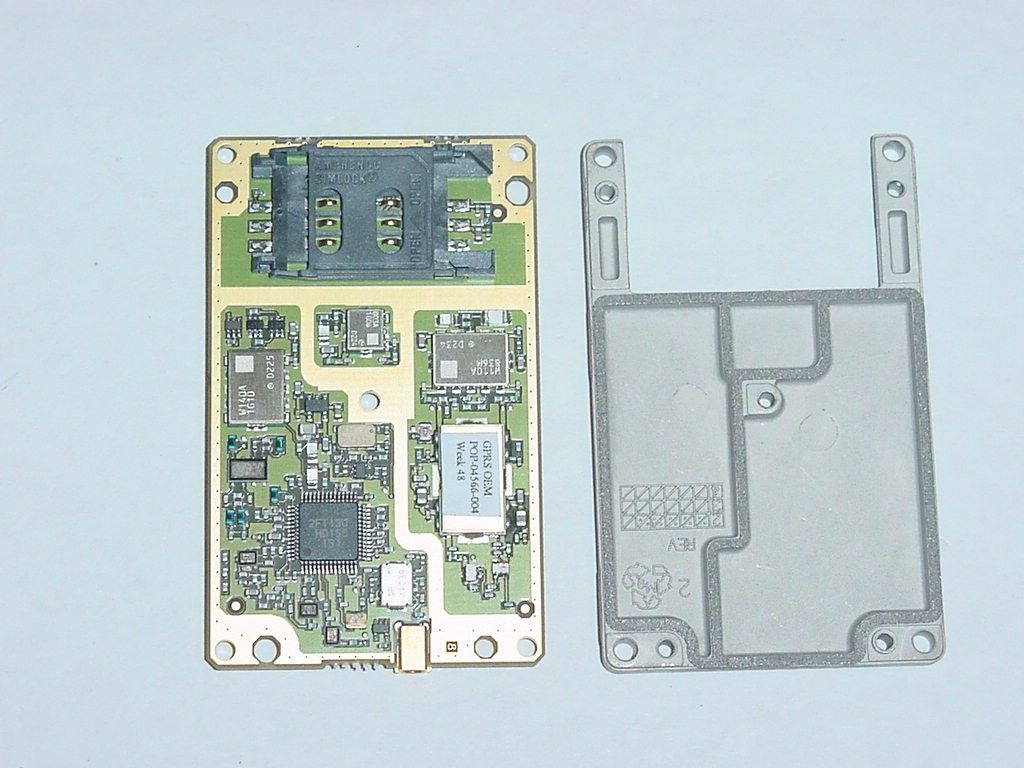
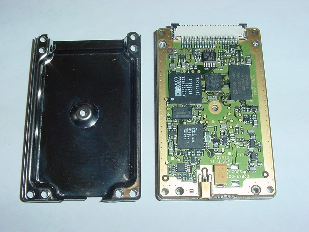
VeriFone Inc. FCC ID: B32OMNI3600G Chassis – Cover off View EUT – Back View of Mother PCB and Front of Radio VeriFone Inc. FCC ID: B32OMNI3600G EUT – Radio Mounting Bracket Side View EUT – Rim 1902 Radio
Operational Description
Verifion Omni 3600G FreqAmplitude 188186.2 Horn 487 Gain = 5.480.8 83784.8 LogP 297 Gain = 6.878 Sample 1 of 2 Polar Plot Data: Horizontal Polarization Frequency of test 1880.998 MHz. 0-7.36 -2-7.38 -2-7.33 -2-7.36 -2-7.38 -2-7.33 0-6.67 2-5.54 4-4.24 6-3.61 7-4.1 10-5.89 11-8.96 13-11.97 15-12.72 17-11.39 19-11.03 21-12.55 23-13.75 25-11.27 27-8.34 29-6.67 31-6.25 33-6.62 35-7.23 37-8.27 39-10.15 41-13.52 43-20.19 45-25.51 47-15.57 49-11.48 51-8.99 53-7.18 55-6.6 57-7.5 59-9.97 61-12.11 63-12.25 65-11.76 66-11.18 69-9.06 70-6.13 73-4.28 74-3.92 77-5.31 78-8.71 80-15.36 82-14.87 84-13.92 86-17.16 88-8.24 90-3.06 92-1 94-1.27 96-3.82 98-9.13 100-16.13 102-20.05 104-15.78 106-10.06 108-7.68 110-7.36 112-9.5 114-14.8 116-14.48 118-10.22 120-7.99 122-7.16 124-7.66 126-8.87 128-8.82 130-7.06 132-5.58 134-5.33 136-5.31 138-5.06 140-4.24 142-3.39 144-2.86 146-2.39 147-1.86 150-1.05 151-0.03 1540.75 1551.27 1571.36 1590.94 161-0.15 163-1.36 165-2.3 167-3.18 169-4.01 171-4.14 173-3.59 175-2.72 177-2.05 179-2 181-2.65 183-3.89 185-5.26 187-5.84 189-5.33 191-4.49 193-3.94 195-3.52 197-3.48 198-3.87 201-4.4 203-4.45 205-3.96 206-3.13 209-2.42 210-2.46 213-3.68 214-5.58 216-6.65 218-6.18 220-5.58 222-6.13 224-7.75 226-9.41 228-9.85 230-10.01 232-10.43 234-11.55 236-14.2 238-15.8 240-13.78 242-9.2 244-5.24 246-2.49 248-0.84 250-0.15 252-0.15 254-0.53 256-0.77 258-0.86 260-1.29 262-2.65 264-4.54 266-4.96 268-3.18 270-1.89 272-2.03 274-3.06 276-4.14 278-4.17 280-3.82 282-4.06 284-4.75 286-5.1 287-5.06 290-4.82 291-4.68 294-4.94 295-5.84 297-6.83 299-7.36 301-7.68 303-8.1 305-9.87 307-13.5 309-13.34 311-10.34 313-9.41 315-9.8 317-9.15 319-7.09 321-5.26 323-4.19 325-3.48 327-3.11 329-3.66 331-5.72 333-9.59 335-14.97 337-16.26 339-12.97 341-9.8 343-7.38 345-5.79 347-5.19 349-5.12 351-6.06 353-7.5 354-8.31 357-8.06 358-7.16 Polar Plot Data: Horizontal Polarization Sample 2 of 2 Frequency of test 1880.998 MHz. 0-8.71 -1-8.68 -1-8.71 -1-8.73 -1-8.73 -1-8.73 -1-8.73 -1-8.73 0-8.08 2-6.78 4-5.03 6-4.13 8-4.17 10-5.77 12-8.8 14-12.44 16-14.22 18-13.27 19-13.03 22-14.36 23-14.34 26-11.09 27-8.01 30-6.44 31-5.99 33-6.27 35-6.9 37-8.59 39-11.79 41-17.66 43-35.96 45-17.19 47-12.41 49-10.61 51-9.71 53-8.48 55-7.73 57-8.66 59-11.23 61-13.17 63-12.88 65-12.53 67-12.51 69-9.08 71-5.26 73-3.23 75-3.23 77-5.31 79-10.15 81-18.49 83-12.95 85-12.72 87-14.2 89-6.04 91-1.89 93-0.53 95-1.5 97-4.89 99-11.79 101-22.4 102-22.6 105-13.13 106-8.59 109-7.11 110-7.87 112-11.6 114-17.83 116-14.06 118-10.15 120-7.94 122-7.06 124-7.59 126-8.73 128-8.22 130-6.62 132-5.51 134-5.24 136-4.94 138-4.19 140-3.09 142-2.28 144-1.86 146-1.5 148-0.93 150-0.1 1520.75 1541.29 1561.46 1581.22 1600.58 162-0.43 164-1.46 166-2.17 167-2.99 170-3.48 171-3.37 174-2.72 175-1.98 178-1.67 179-2.12 181-3.27 183-4.85 185-5.84 187-5.89 189-5.1 191-4.42 193-3.96 195-3.68 197-3.89 199-4.26 201-4.47 203-4.14 205-3.61 207-2.95 209-2.65 211-3.3 213-5.1 215-7.18 217-7.75 219-6.74 221-6.23 223-6.95 225-8.52 227-9.59 229-9.57 231-9.36 233-9.62 235-11.16 237-14.15 239-15.69 241-12.81 243-8.08 245-4.14 247-1.69 249-0.33 2500.11 253-0.12 254-0.67 257-1.05 258-1.29 260-1.91 262-3.23 264-4.8 266-4.7 268-2.92 270-1.93 272-2.3 274-3.41 276-4.45 278-4.59 280-4.28 282-4.56 284-5.19 286-5.47 288-5.36 290-5.06 292-4.87 294-5.17 296-6.02 298-7.16 300-8.17 302-8.99 304-9.43 306-11.2 308-14.69 310-14.27 312-11.39 314-10.77 316-11.25 318-9.92 320-7.23 322-5.31 324-4.31 326-3.71 328-3.37 330-3.82 331-5.82 334-9.9 335-16.44 338-17.94 339-14.1 342-11.16 343-8.31 346-6.65 347-5.65 350-5.56 351-6.65 353-8.2 355-9.24 357-9.2 359-8.34 Polar Plot Data: Horizontal Polarization Sample 2 of 2 837 MHz Frequency of test 837.003 MHz. 0-5.95 -1-5.93 1-5.64 3-5.75 5-6.02 6-6.26 8-6.6 10-6.6 12-6.37 14-6.02 16-5.91 18-5.98 20-6.23 22-6.49 23-6.62 26-6.42 27-5.91 29-5.75 31-5.59 33-5.91 35-6.51 37-7.74 39-9.12 41-10.76 42-11.91 44-11.67 46-10.2 48-8.06 50-6.14 52-4.36 54-2.94 56-1.74 58-0.82 630.88 651.04 661.26 681.31 701.26 721.04 740.85 760.64 780.5 800.55 820.78 831.03 851.47 871.82 892.24 912.58 932.87 953.08 973.15 983.17 1003.17 1023.2 1043.27 1063.43 1083.72 1104.12 1124.55 1144.93 1155.28 1185.48 1195.53 1215.35 1235.03 1254.48 1273.86 1293.13 1302.39 1321.7 1341.31 1361.1 1381.29 1401.61 1422.1 1442.58 1463.06 1473.5 1503.86 1514.03 1534.1 1553.98 1573.75 1593.48 1613.2 1622.99 1642.83 1662.77 1682.83 1702.99 1723.29 1743.63 1763.96 1784.27 1804.55 1824.67 1834.79 1854.79 1874.64 1894.41 1914.18 1933.93 1953.7 1973.51 1983.27 2003.01 2022.79 2042.65 2062.63 2082.65 2102.67 2122.63 2142.51 2152.37 2172.35 2192.53 2212.89 2233.38 2253.93 2274.37 2294.71 2304.93 2324.91 2344.53 2364 2383.34 2402.63 2422 2441.4 2461.02 2470.78 2490.74 2510.83 2530.92 2551.15 2571.4 2591.63 2611.79 2621.93 2642.03 2662.1 2682.12 2702.03 2721.79 2741.59 2761.29 2780.99 2790.6 2810.11 283-0.45 285-1.07 287-1.71 289-2.46 291-3.03 293-3.45 295-3.75 297-4.03 298-4.4 300-4.92 302-5.59 304-6.19 306-6.62 308-6.69 310-6.4 312-5.93 314-5.57 315-5.34 317-5.48 319-5.73 321-6.07 323-6.07 325-5.87 327-5.22 329-4.19 330-2.96 333-1.74 334-0.77 336-0.1 3380.25 3400.09 342-0.43 344-1.33 346-2.67 348-4.22 350-6 351-7.39 353-8.09 355-7.71 357-6.95 359-6.02 Polar Plot Data: Horizontal Polarization Sample 1 of 2, 837 MHz Frequency of test 836.998 MHz. 0-12 -3-12.02 -1-12.44 1-11.34 2-11.01 4-9.92 6-9.64 8-9.85 10-9.24 12-8.59 14-7.71 16-7.13 18-6.85 19-6.69 21-6.88 23-6.83 25-6.28 27-5.45 29-4.71 31-4.05 33-3.75 35-4.05 36-4.85 38-6.14 40-8.57 42-11.91 44-18.06 46-24.97 48-16.05 50-11.27 52-8.3 54-6.3 55-4.85 57-3.57 59-2.48 61-1.48 63-0.59 650.16 670.74 691.15 701.26 721.19 740.99 760.71 780.42 800.23 820.14 840.09 860.28 870.48 890.95 911.5 932 952.44 972.86 993.08 1013.36 1023.48 1043.72 1064.03 1084.3 1104.79 1125.07 1145.4 1165.67 1185.71 1195.69 1215.43 1235.14 1254.6 1274.03 1293.41 1312.74 1332.32 1341.98 1361.93 1382.12 1402.28 1422.74 1443.08 1463.27 1483.65 1503.84 1513.91 1533.86 1553.68 1573.58 1593.38 1613.22 1633.15 1653.…
Text truncated - open the document above for the full version.
Operational Description
Peak Gain (dB):0.25 Total Radiated power (dBm):8.01 Frequency (MHz):1710.00 Cable Attenuation (dB):1.15 Receive Antenna Gain (dB):2.15 Separation (m):1.27 unit 6 w MMCX to pad whole unit 4 screws 1710Mhz low loss cable 1 Horizontal Polarization Dec 20, 2002 10:54 AM Measured Tx Power (dBm):10.81 Horz. Component (dBm): 3.77 unit 6 w MMCX to pad whole unit 4 screws 1710Mhz low loss cable 1 Vertical Polarization Dec 20, 2002 10:54 AM Peak Gain (dB):1.03 Frequency (MHz):1710.00 Cable Attenuation (dB):1.15 Receive Antenna Gain (dB):2.15 Tx Power (dBm):10.81 Separation (m):1.27 Measured Vert. Component (dBm); 5.96 Total Radiated power (dBm):8.01
Operational Description
Peak Gain (dB):1.86 Total Radiated power (dBm):8.54 Frequency (MHz):1784.00 Cable Attenuation (dB):1.22 Receive Antenna Gain (dB):2.15 Separation (m):1.27 unit 6 w MMCX to pad whole unit 4 screws 1784Mhz low loss cable 1 Horizontal Polarization Dec 20, 2002 11:23 AM Measured Tx Power (dBm):10.80 Horz. Component (dBm): 4.52 unit 6 w MMCX to pad whole unit 4 screws 1784Mhz low loss cable 1 Vertical Polarization Dec 20, 2002 11:23 AM Peak Gain (dB):1.86 Frequency (MHz):1784.00 Cable Attenuation (dB):1.22 Receive Antenna Gain (dB):2.15 Tx Power (dBm):10.80 Separation (m):1.27 Measured Vert. Component (dBm); 6.32 Total Radiated power (dBm):8.54
Operational Description
Peak Gain (dB):-0.08 Total Radiated power (dBm):6.87 Frequency (MHz):890.00 Cable Attenuation (dB):0.80 Receive Antenna Gain (dB):2.15 Separation (m):1.24 unit #6 whole unit mmcx to pad low power level Horizontal Polarization Dec 20, 2002 12:29 PM Measured Tx Power (dBm):10.70 Horz. Component (dBm): 4.08 unit #6 whole unit mmcx to pad low power level Vertical Polarization Dec 20, 2002 12:29 PM Peak Gain (dB):0.44 Frequency (MHz):890.00 Cable Attenuation (dB):0.80 Receive Antenna Gain (dB):2.15 Tx Power (dBm):10.70 Separation (m):1.24 Measured Vert. Component (dBm); 3.65 Total Radiated power (dBm):6.87
Operational Description
Peak Gain (dB):-0.86 Total Radiated power (dBm):5.47 Frequency (MHz):915.00 Cable Attenuation (dB):0.80 Receive Antenna Gain (dB):2.15 Separation (m):1.24 unit #6 whole unit mmcx to pad low power level 915MHz Horizontal Polarization Dec 20, 2002 12:58 PM Measured Tx Power (dBm):10.00 Horz. Component (dBm): 2.91 unit #6 whole unit mmcx to pad low power level 915MHz Vertical Polarization Dec 20, 2002 12:58 PM Peak Gain (dB):-0.06 Frequency (MHz):915.00 Cable Attenuation (dB):0.80 Receive Antenna Gain (dB):2.15 Tx Power (dBm):10.00 Separation (m):1.24 Measured Vert. Component (dBm); 1.97 Total Radiated power (dBm):5.47
Parts List/Tune Up Info
VeriFone Inc. 3755 Atherton Road Rocklin, CA 95765-3701 Tel: 916/630-0550 Fax: 916/630-2501 Date: August 6, 2003 Federal Communication Commission Office of Engineering Technology Equipment Authorization Division Subject: Tune-up Procedure To Whom It May Concern: All settings are made at the Original Equipment Manufacture (OEM) factory for the 1902G radio, FCC ID L6AR6420GN, consumers are not able to make adjustments. The 1902G radio is incorporated into the following VeriFone product. VeriFone Product Name – Omni 3600G VeriFone FCC ID – B32OMNI3200G Sincerely: Technical Staff Senior EMC Engineer William Morse NCE Phone 916.630.2540 FAX 916.630.2501 EMAIL [email protected]
RF Exposure Info
Note: This test report is specially limited to the above client company and the product model only. It may not be duplicated without prior written consent of Bay Area Compliance Laboratory Corporation. This report must not be used by the client to claim product endorsement by NVLAP or any agency of the U.S. Government. SAR EVALUATION REPORT For VeriFone Inc. 3755 Atherton Road Rocklin, CA 95765 FCC ID: B32OMNI3600G 2003-07-17 This Report Concerns: Original Report Equipment Type: Wireless Point of Sale Terminal Test Engineer:Eric Hong Report No.:R0305223S Test Date:2003-07-11, 2003-07-14 Reviewed By:Hans Mellberg Prepared By:Bay Area Compliance Laboratory Corporation 230 Commercial Street Sunnyvale, CA 94085 Tel: (408) 732-9162 Fax: (408) 732 9164 VeriFone Inc. FCC ID: B32OMNI3600G Report #R0305223S SAR Evaluation Report Page 2 of 59 TABLE OF CONTENTS SUMMARY........................................................................................................................................................................................3 1 - REFERENCE..............................................................................................................................................................................4 2 - TESTING EQUIPMENT.......................................................................…
Text truncated - open the document above for the full version.
Contact Information
Applicant
Kenji Chao(Sr. Director, Hardware Engineering)
Test Firm
Bay Area Compliance LaboratoryJohn Chan
Technical Specifications
| # | Rule Parts | Frequency Range | Power Output | Emission | Tolerance |
|---|---|---|---|---|---|
| 2 | 24E | 1.85 GHz - 1.91 GHz | 394.00 mW | 592KGXW | 2.5 ppm |
Other Applications from VeriFone Inc
B32VS100P
Jun 22, 2026Point of Sale Terminal
Equipment Class
DXX - Part 15 Low Power Communication Device Transmitter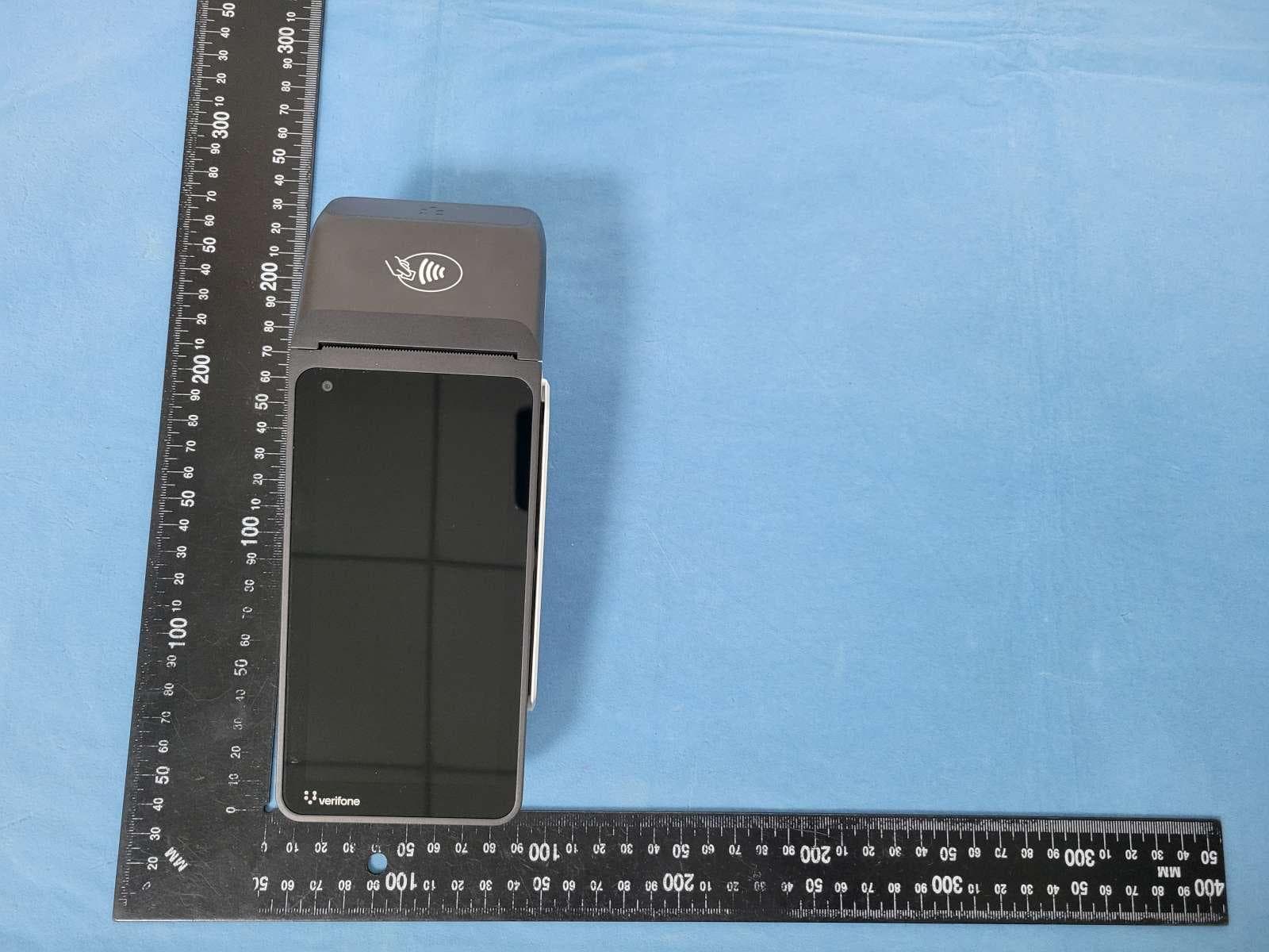
B32V660CA2
Apr 20, 2026Point of Sale Terminal
Equipment Class
NII - Unlicensed National Information Infrastructure TX
B32VM110R
Mar 31, 2026Point of Sale Terminal
Equipment Class
PCB - PCS Licensed Transmitter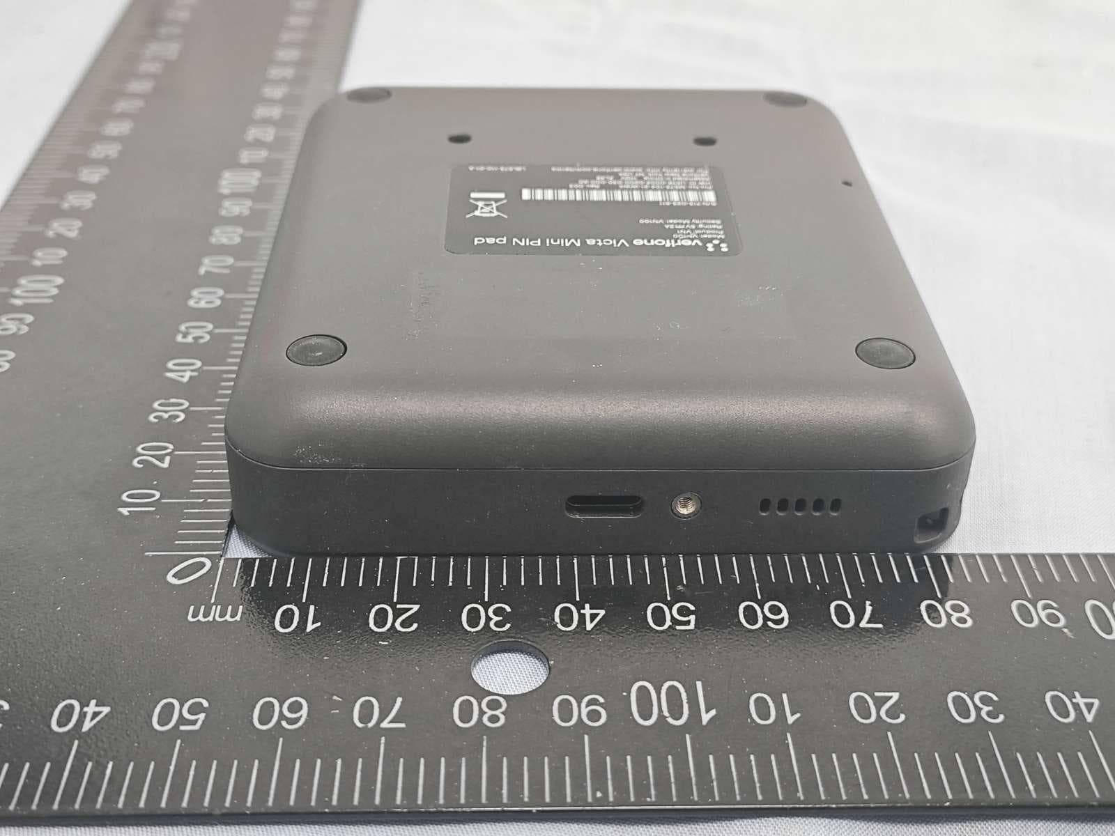
B32VN100
Feb 02, 2026Point of Sale Terminal
Equipment Class
DXX - Part 15 Low Power Communication Device Transmitter
B32VS100M
Dec 03, 2025Point of Sale Terminal
Equipment Class
PCE - PCS Licensed Transmitter held to ear