B32OMNI56XXGWireless POS Terminal
VeriFone Inc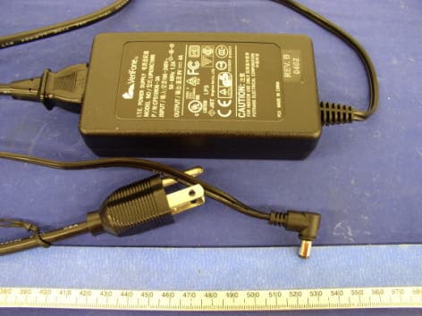
Click to zoom
Application Details
- Equipment Class
- PCB - PCS Licensed Transmitter
- Date of Grant
- Aug 30, 2004
- Application Purpose
- Original Equipment
- Date of Application
- Aug 30, 2004
- Equipment Note
- Wireless POS Terminal
- Frequency Range
- 824.20000000 - 848.80000000
- Company
- VeriFone Inc
- Country
- United States
Documents & Files
Document Text
Text extracted from the exhibit documents filed with the FCC. Open a document above to read the original.
Users Manual
VeriFone Part Number 23216, Revision A.1 V E R I F O N E C O N F I D E N T I A L R A FT Omni 5xxx Installation Guide All rights reserved. No part of the contents of this document may be reproduced or transmitted in any form without the written permission of VeriFone, Inc. The information contained in this document is subject to change without notice. Although VeriFone has attempted to ensure the accuracy of the contents of this document, this document may include errors or omissions. The examples and sample programs are for illustration only and may not be suited for your purpose. You should verify the applicability of any example or sample program before placing the software into productive use. This document, including without limitation the examples and software programs, is supplied “As-Is.” VeriFone, Inc. 2455 Augustine Drive Santa Clara CA 95054-3002 www.verifone.com VeriFone Part Number 23216, Revision A.1 Omni 5xxx Installation Guide © 2004 VeriFone, Inc. VeriFone, the VeriFone logo, Omni, VeriCentre, Verix, and ZonTalk are registered trademarks of VeriFone. Other brand names or trademarks associated with VeriFone’s products and services are trademarks of VeriFone, Inc. All other brand names and trademarks appearing in this manual are the property of their respective holders. Comments? Please e-mail all comments in this document to [email protected] WARNING Do not dispose of the Li-ion smart battery in a fire. Li-ion batteries must be recycled or disposed of properly. Do not dispose of Li-ion batteries in municipal waste sites. V E R I F O N E C O N F I D E N T I A L R A FT OMNI 5XXX INSTALLATION GUIDE3 CONTENTS PREFACE . . . . . . . . . . . . . . . . . . . . . . . . . . . . . . . . . . . . . . . 5 Audience. . . . . . . . . . . . . . . . . . . . . . . . . . . . . . . . . . . . . . . . . . . . . . . . . . . . . . . . 5 Organization . . . . . . . . . . . . . . . . . . . . . . . . . . . . . . . . . . . . . . . . . . . . . . . . . . . . . 5 Related Documentation . . . . . . . . . . . . . . . . . . . . . . . . . . . . . . . . . . . . . . . . . . . . 5 Conventions and Acronyms . . . . . . . . . . . . . . . . . . . . . . . . . . . . . . . . . . . . . . . . . 6 Document Conventions. . . . . . . . . . . . . . . . . . . . . . . . . . . . . . . . . . . . . . . . . . 6 Acronym Definitions . . . . . . . . . . . . . . . . . . . . . . . . . . . . . . . . . . . . . . . . . . . . 6 CHAPTER1 Terminal OverviewFeatures and Benefits . . . . . . . . . . . . . . . . . . . . . . . . . . . . . . . . . . . . . . . . . . . . 10 Exceptional Ease of Use . . . . . . . . . . . . . . . . . . . . . . . . . . . . . . . . . . . . . . . . . . . . . . . . . 10 Countertop Performance in a “Hand-Over” Design. . . . . . . . . . . . . . . . . . . . 10 True Multi-Application Capability . . . . . . . . . . . . . . . . . . . . . . . . . . . . . . . . . 10 CHAPTER2 Terminal SetupSelect Terminal Location . . . . . . . . . . . . . . . . . . . . . . . . . . . . . . . . . . . . . . . . . . 11 Ease of Use . . . . . . . . . . . . . . . . . . . . . . . . . . . . . . . . . . . . . . . . . . . . . . . . . 11 Environmental Factors . . . . . . . . . . . . . . . . . . . . . . . . . . . . . . . . . . . . . . . . . 11 Electrical Considerations . . . . . . . . . . . . . . . . . . . . . . . . . . . . . . . . . . . . . . . 11 Unpack the Shipping Carton. . . . . . . . . . . . . . . . . . . . . . . . . . . . . . . . . . . . . . . . 12 Examine Terminal Features . . . . . . . . . . . . . . . . . . . . . . . . . . . . . . . . . . . . . . . . 13 Front Panel . . . . . . . . . . . . . . . . . . . . . . . . . . . . . . . . . . . . . . . . . . . . . . . . . . 13 Connection Ports . . . . . . . . . . . . . . . . . . . . . . . . . . . . . . . . . . . . . . . . . . . . . 14 Establish Telephone Line Connections . . . . . . . . . . . . . . . . . . . . . . . . . . . . . . . 15 Install Paper Roll . . . . . . . . . . . . . . . . . . . . . . . . . . . . . . . . . . . . . . . . . . . . . . . . 16 Install/Replace MSAM Cards . . . . . . . . . . . . . . . . . . . . . . . . . . . . . . . . . . . . . . . 18 Connect Optional Device(s) . . . . . . . . . . . . . . . . . . . . . . . . . . . . . . . . . . . . . . . . 19 Connect PIN Pad or Smart Card Reader . . . . . . . . . . . . . . . . . . . . . . . . . . . 20 Connect Check Reader. . . . . . . . . . . . . . . . . . . . . . . . . . . . . . . . . . . . . . . . . 21 External Printers Supported . . . . . . . . . . . . . . . . . . . . . . . . . . . . . . . . . . . . . 22 Connect Terminal Power Pack . . . . . . . . . . . . . . . . . . . . . . . . . . . . . . . . . . . . . . 22 Smart Card Transaction . . . . . . . . . . . . . . . . . . . . . . . . . . . . . . . . . . . . . . . . . . . 23 Magnetic Card Reader Use . . . . . . . . . . . . . . . . . . . . . . . . . . . . . . . . . . . . . . . . 23 CHAPTER3 SpecificationsPower . . . . . . . . . . . . . . . . . . . . . . . . . . . . . . . . . . . . . . . . . . . . . . . . . . . . . . . . . 25 DC Power Pack . . . . . . . . . . . . . . . . . . . . . . . . . . . . . . . . . . . . . . . . . . . . . . . . . 25 Temperature . . . . . . . . . . . . . . . . . . . . . . . . . . . . . . . . . . . . . . . . . . . . . . . . . . . . 25 External Dimensions. . . . . . . . . . . . . . . . . . . . . . . . . . . . . . . . . . . . . . . . . . . . . . 25 Weight . . . . . . . . . . . . . . . . . . . . . . . . . . . . . . . . . . . . . . . . . . . . . . . . . . . . . . . . 25 CHAPTER4 MaintenanceClean the Terminal . . . . . . . . . . . . . . . . . . . . . . . . . . . . . . . . . . . . . . . . . . . . . . . 27 Smart Card Reader . . . . . . . . . . . . . . . . . . . . . . . . . . . . . . . . . . . . . . . . . . . . . . 27 CONTENTS 4OMNI 5XXX INSTALLATION GUIDE V E RI F O NE C O NF I D E N T I A L R A FT CHAPTER5 VeriFone Service and Support Return a Terminal for Service. . . . . . . . . . . . . . . . . . . . . . . . . . . . . . . . . . . . . . . 29 Accessories and Documentation . . . . . . . . . . …
Text truncated - open the document above for the full version.
Attestation Statements
VeriFone Inc. 3755 Atherton Road Rocklin, CA 95765-3701 Tel: 916/630-0550 Fax: 916/630-2501 Federal Communications Commission Authorization and Evaluation Division Confidentiality Request regarding application for certification of FCC ID: B32OMNI56XXG Pursuant to Sections 0.457 and 0.459 of the Commission’s Rules, we hereby request confidential treatment of information accompanying this application as outlined below: Schematics Engineering Requirements Specification (ERS) Block Diagram Antenna Specifications Parts list The above materials contain trade secrets and proprietary information not customarily released to the public. The public disclosure of these materials may be harmful to the applicant and provide unjustified benefits to its competitors. The applicant understands that pursuant to Section 0.457 of the Rules, disclosure of this application and all accompanying documentation will not be made before the date of the Grant for this application. Sincerely, Project Manager Pushpinder Sawanni Phone 916.630.3536 FAX 916.630.2501 EMAIL Pushpinder [email protected]
External Photos
EXHIBIT C - EUT PHOTOGRAPHS EUT Front View EUT Rear View Power Adapter View
ID Label/Location Info
EXHIBIT A - FCC ID LABELING AND WARNING STATEMENT Proposed FCC ID Label Specifications: Text is black or white in color and is left justified. Labels are silk-screened and shall be “permanently affixed” at a conspicuous location on the EUT. Proposed Label Location on EUT Rear View of the EUT/Proposed ID Label Location FCC Warning Statement A FCC Warning Statement is provided in the product manual. FCC ID: B32OMNI56XXG FCC ID: B32OMNI56XXG
Internal Photos
EUT Cover Off View EUT Component View EUT Solder View Battery View Antenna View EUT Component with Shielding View GPRS Module Component View GPRS Module Component without Shielding View GPRS Module Solder View GPRS Interface Board View GPRS Interface Board Solder View GPRS Interface Board Component View with GPRS Module GPRS Interface Board Component View without GPRS Module
Operational Description
VeriFone Inc. 3755 Atherton Road Rocklin, CA 95765-3701 Tel: 916/630-0550 Fax: 916/630-2501 Date: August 5, 2004 System Description The Omni 56XXG is VeriFone’s GSM/GPRS portable payment device. This version of the Omni 56XX family is running on the GSM/GPRS radio network for North America it incorporates a Radio Modem previously certified under FCC ID: QIPMC56 operating in the frequency range of 824 – 849MHz and 1850 – 1910MHz which are the 850MHz and 1900MHz bands. Each device is integrated with the following: LCD display Magnetic stripe card reader Primary smart card reader 3 SAM’s “Secure Access Module” High-speed thermal printer Removable/rechargeable battery 32-bit RISC processor Omni 56XX System Function Description The power source for the Omni 56XX is either a 7.2VDC 1800mAh LI-ION battery module, which is the main power source, or an external AC power adapter that can be plugged into a 100- 240VAC source to supply 9.5vdc at 4A. Communications to the radio are provided by the system CPU serial port 3. The software loaded inside physically and electronically secure area of the Omni 56XX provides further control of the QIPMC56 User interface is provided through the front keys of the unit with the LCD display providing Project Manager Pushpinder Sawanni Phone 916.630.3536 FAX 916.630.2501 EMAIL [email protected]
Operational Description
Predator Portable ERS VDN 2xxxx Revision 1 VeriFone, Inc. Confidential Page 1 Predator Portable ERS CONFIDENTIAL VERIFONE DOCUMENT: VDN 2XXXX REVISION: 1 DATE: 18 JUN 2004 Predator Portable ERS VDN 2xxxx Revision 1 VeriFone, Inc. Confidential Page 2 Revision History Revision Date Description Changed By 1 18 Nov 03 First Draft with baseline from VDN23307, Predator ERS Mark Cleary Predator Portable ERS VDN 2xxxx Revision 1 VeriFone, Inc. Confidential Page 3 Table of Contents 1. Glossary..............................................................................................................................................4 2. Introduction........................................................................................................................................5 2.1. PURPOSE........................................................................................................................................5 2.2. REFERENCES...................................................................................................................................5 3. Product Overview................................................................................................................................5 4. Required Feature List..........................................................................................................................5 5. Hardware Characteristics....................................................................................................................7 5.1. ERGONOMICS..................................................................................................................................7 5.2. DISPLAY..........................................................................................................................................8 5.3. KEYPAD INPUT.................................................................................................................................8 5.4. COMMUNICATION PORTS...................................................................................................................9 5.5. INTEGRATED MODEM.......................................................................................................................11 5.6. MAGNETIC CARD READER.................................................................................................................11 5.7. SMART CARD READER & SECURITY ACCESS MODULE READERS.............................................................12 5.8. INTEGRATED PRINTER......................................................................................................................14 5.9. SECURITY CIRCUIT..........................................................................................................................14 5.10. POWER PACK..............................................................................................................................15 5.11. PHYSICAL AND ENVIRONMENTAL SPECIFICATIONS.............................................................................16 5.12. PRODUCT CERTIFICATION GUIDELINES............................................................................................16 5.13. SHOCK AND VIBRATION SPECIFICATIONS..........................................................................................18 5.14. MECHANICAL SPECIFICATIONS.......................................................................................................18 5.15. BASE PLATFORM OPTIONS............................................................................................................18 6. Lifecycle.............................................................................................................................................19 6.1. MANUFACTURING............................................................................................................................19 6.2. DISTRIBUTION.................................................................................................................................20 6.3. REPAIR..........................................................................................................................................21 6.4. END OF LIFE...................................................................................................................................21 7. Requirements Traceability Matrix......................................................................................................21 Predator Portable ERS VDN 2xxxx Revision 1 VeriFone, Inc. Confidential Page 4 1. Glossary AES Advanced Encryption Standard Algorithm selected by NIST (Rijndael) API Application Programming Interface ARM Advanced RISC Machines ASIC Application Specific Integrated Circuit CAPK Certification Authority Public Key as in the EMV standard CBC Cipher Block Chaining mode, as defined in ANSI X3.106 COG Chip on Glass COGS Cost of Goods Sold COTS Commercial Off-the-Shelf CTS Clear to Send DEA/DES Data Encryption Algorithm/Standard, as defined in ANSI X3.92 DTR Data Terminal Ready DUKPT Derived Unique Key Per Transaction Method as defined in the VISA’s POS Equipment Requirement: PIN processing and Data Authentication, International Version 1.0, August 1988 ECB Electronic Code Book mode, as defined in ANSI X3.106 ECR Electronic Cash Register EMV Joint Europay, MasterCard and Visa Standard EOL End of Life ERS Engineering Requirements Specification GID Group Identifier - Concept inherited from Verix terminals file system HDLC High-level Data Link Control ICC Integrated Chip Card (Smart Card) LCD Liquid Crystal Display MAC Message Authentication Code, as defined in ANSI X9.19 MMU Memory Management Unit MSAM Multiple Secure Access Module MSR Magnetic Stripe Reader OS Operating System PED PIN Entry Device PIN Personal Identification Number POS Point-of-Sale PRD Product Requirement Document PSCR Primary Smart Card Reader RTS Ready to Send SOC System on Chip SAM Secure Access Module S…
Text truncated - open the document above for the full version.
Operational Description
SPECIFICATION FOR APPROVAL CUSTOMER DATE DESCRIPTION CUSTOMER P/N Part No. 03/01/04 GPRS-USA DUAL BAND GPRS USA Dual Band Verifone Table of Contents Cover Page .........1 Table of Contents.........2 Specification.........3 Antenna Drawing.........4 Electrical Properties V.S.W.R.........5 Gain .........5 SPECIFICATION 1.Description: GPRS USA Dual Band 2.Customer: VeriFone 3.Part No.: GPRS-USA DUAL BAND 4.Standard: GPRS 5.Antenna Profile: 45.5 mm 6.Electrical Characteristics Operating Frequency: 824~894 MHz and 1850~1990 MHz Polarization Type: Vertical Type of Radiation: Near omni-directional in the horizontal plane Peak Gain: 0 dBi (Max) Impedance: 50 Ω (Typ.) V.S.W.R.: 824 MHz 2.6 894 MHz 1.4 1850 MHz 1.55 1990 MHz 2.1 7.Mechanical Characteristics Action: Swivel Type Connector: SMA R/A improved type 8.Raw Material Housing: TPU Electrical Properties V.S.W.R
Parts List/Tune Up Info
VeriFone Inc. 3755 Atherton Road Rocklin, CA 95765-3701 Tel: 916/630-0550 Fax: 916/630-2501 Date: August 20, 2004 Federal Communication Commission Office of Engineering Technology Equipment Authorization Division Subject: Tune-up Procedure To Whom It May Concern: All settings are made at the Original Equipment Manufacture (OEM) factory for the MC56 radio, FCC ID: QIPMC56, consumers are not able to make adjustments. VeriFone has verified that the MC56 can be tuned up to 824-849MHZ at 33dBm, and 1850- 1910MHz at 30dBm, and operate properly. The MC56 radio is incorporated into the following VeriFone product. VeriFone Product Name – Omni 56XX VeriFone FCC ID – B32OMNI56XXG Sincerely: Project Manager Pushpinder Sawanni Phone 916.630.3536 FAX 916.630.2501 EMAIL Pushpinder [email protected]
Parts List/Tune Up Info
MC55/56 Hardware Interface Description Confidential / Released s mo b i l e MC55/56_hd_v01.05 Page 1 of 101 11.02.2004 MC55/56 Siemens Cellular Engine Version: 01.05 DocID: MC55/56_hd_v01.05 MC55/56 Hardware Interface Description Confidential / Released s mo b i l e MC55/56_hd_v01.05 Page 2 of 101 11.02.2004 Document Name: MC55/56 Hardware Interface Description Version: 01.05 Date: February 11, 2004 DocId: MC55/56_hd_v01.05 Status: Confidential / Released General Notes Product is deemed accepted by recipient and is provided without interface to recipientís products. The documentation and/or product are provided for testing, evaluation, integration and information purposes. The documentation and/or product are provided on an ìas isî basis only and may contain deficiencies or inadequacies. The documentation and/or product are provided without warranty of any kind, express or implied. To the maximum extent permitted by applicable law, Siemens further disclaims all warranties, including without limitation any implied warranties of merchantability, completeness, fitness for a particular purpose and non-infringement of third-party rights. The entire risk arising out of the use or performance of the product and documentation remains with recipient. This product is not intended for use in life support appliances, devices or systems where a malfunction of the product can reasonably be expected to result in personal injury. Applications incorporating the described product must be designed to be in accordance with the technical specifications provided in these guidelines. Failure to comply with any of the required procedures can result in malfunctions or serious discrepancies in results. Furthermore, all safety instructions regarding the use of mobile technical systems, including GSM products, which also apply to cellular phones must be followed. Siemens or its suppliers shall, regardless of any legal theory upon which the claim is based, not be liable for any consequential, incidental, direct, indirect, punitive or other damages whatsoever (including, without limitation, damages for loss of business profits, business interruption, loss of business information or data, or other pecuniary loss) arising out the use of or inability to use the documentation and/or product, even if Siemens has been advised of the possibility of such damages. The foregoing limitations of liability shall not apply in case of mandatory liability, e.g. under the German Product Liability Act, in case of intent, gross negligence, injury of life, body or health, or breach of a condition which goes to the root of the contract. However, claims for damages arising from a breach of a condition, which goes to the root of the contract, shall be limited to the foreseeable damage, which is intrinsic to the contract, unless caused by intent or gross negligence or based on liability for injury of life, body or health. The above provision does not imply a change on the burden of proof to the detriment of the recipient. Subject to change without notice at any time. The interpretation of this general note shall be governed and construed according to German law without reference to any other substantive law. Copyright Transmittal, reproduction, dissemination and/or editing of this document as well as utilization of its contents and communication thereof to others without express authorization are prohibited. Offenders will be held liable for payment of damages. All rights created by patent grant or registration of a utility model or design patent are reserved. Copyright © Siemens AG 2004 MC55/56 Hardware Interface Description Confidential / Released s mo b i l e MC55/56_hd_v01.05 Page 3 of 101 11.02.2004 Contents 0 Document History ...................................................................................................... 7 1 Introduction ................................................................................................................ 8 1.1 Related documents ............................................................................................. 8 1.2 Terms and abbreviations..................................................................................... 9 1.3 Type approval ....................................................................................................12 1.4 Safety precautions .............................................................................................14 2 Product concept........................................................................................................16 2.1 MC55/56 key features at a glance......................................................................17 2.2 Circuit concept ...................................................................................................20 3 Application Interface.................................................................................................21 3.1 Operating modes...............................................................................................22 3.2 Power supply.....................................................................................................24 3.2.1 Power supply pins on the board-to-board connector.............................24 3.2.2 Minimizing power losses.......................................................................25 3.2.3 Monitoring power supply.......................................................................25 3.3 Power up / down scenarios ................................................................................26 3.3.1 Turn on MC55/56 .................................................................................26 3.3.1.1 Turn on MC55/56 using the ignition line /IGT (Power on) ..........27 3.3.1.2 Timing of the ignition process ...................................................28 3.3.1.3 Turn on MC55/56 using the POWER signal ..............................29 3.3.1.4 Turn on MC55/56 using the RTC (Alarm mode).................…
Text truncated - open the document above for the full version.
Parts List/Tune Up Info
Tune-up procedure explaination From: Peters Uwe ICM WM AE TS <[email protected]> To: [email protected] Cc: "'Richard Dias'" <[email protected]> Subject: AW: Tuning Up Procedure Date: Mon, 6 Sep 2004 10:34:13 +0200 X-Mailer: Internet Mail Service (5.5.2657.72) X-MAIL: maisqr.baclcorp.com i868Wn8P092475 X-RCPT-TO: <[email protected]> Shirley, regarding your question for a tune up procedure of our MC56 , the MC56 is a fully FCC and PTCRB approved device and for the first filing we used the same tune up documents for FCC as we provided it to you ( Siemens HID MC56 doc. ) and FCC/TCB was satisfied. When the customer is implementing our module in his application the customer could not modify any parameter of our module, there is no access to tune up the power out put of the module or any other parameter the serial interface is locked internally for tune procedure. For the customer it is only possible to connect his own antenna to our device. Of course could w Siemens provide you with the TCF docs for second filing for the Verifone product. Please let me know your comments. Best regards Uwe Peters Page 1
RF Exposure Info
Note: This test report is specially limited to the above client company and the product model only. It may not be duplicated without prior written consent of Bay Area Compliance Laboratory Corporation. This report must not be used by the client to claim product certification, approval, or endorsement by NVLAP, NIST or any agency of the U.S. Government. SAR EVALUATION REPORT For VeriFone Inc. 3755 Atherton Road, Rocklin, CA 95765 FCC ID: B32OMNI56XXG 2004-08-12 This Report Concerns: Original Report Equipment Type: Wireless POS Terminal Test Engineer: Eric Hong / Report No.: R0407301S Test Date: 2004-08-12 Reviewed By: Ming Jing / Prepared By: Bay Area Compliance Laboratory Corporation (BACL) 230 Commercial Street Sunnyvale, CA 94085 Tel: (408) 732-9162 Fax: (408) 732 9164 VeriFone Inc. FCC ID: B32OMNI56XXG Report #R0407301S SAR Evaluation Report Page 2 of 83 TABLE OF CONTENTS SUMMARY.......................................................................................................................................................................................3 1 - REFERENCE.............................................................................................................................................................................4 2 - TESTING EQUIPMENT........................................................................................................................................................5 2.1 EQUIPMENTS LIST & CALIBRATION INFO............................................................................................................................5 2.2 EQUIPMENT CALIBRATION CERTIFICATE.............................................................................................................................5 3 - EUT DESCRIPTION..............................................................................................................................................................44 4 - SYSTEM TEST CONFIGURATION................................................................................................................................45 4.1 JUSTIFICATION........................................................................................................................................................................45 4.2 EUT EXERCISE PROCEDURE................................................................................................................................................45 4.3 EQUIPMENT MODIFICATIONS...............................................................................................................................................45 5 – CONDUCTED OUTPUT POWER MEASUREMENTS.............................................................................................46 5.1 PROVISION APPLICABLE.......................................................................................................................................................46 5.2 TEST PROCEDURE...................................................................................................................................................................46 5.3 TEST EQUIPMENT....................................................................................................................................................................46 5.4 TEST RESULTS........................................................................................................................................................................46 6 - DOSIMETRIC ASSESSMENT SETUP............................................................................................................................49 6.1 MEASUREMENT SYSTEM DIAGRAM....................................................................................................................................50 6.2. SYSTEM COMPONENTS.........................................................................................................................................................51 6.3 MEASUREMENT UNCERTAINTY...........................................................................................................................................55 7 - EVALUATION PROCEDURE...........................................................................................................................................56 7.1 BODY SAR EVALUATION PROCEDURE..............................................................................................................................56 7.2 EXPOSURE LIMITS..................................................................................................................................................................57 7.3 SIMULATED TISSUE LIQUID PARAMETER CONFIRMATION..............................................................................................57 7.4 SAR MEASUREMENT............................................................................................................................................................57 7.5 SYSTEM ACCURACY VERIFICATION....................................................................................................................................58 7.6 LIQUID MEASUREMENT RESULT..........................................................................................................................................59 8 - SAR TEST RESULTS............................................................................................................................................................64 8.1 SAR BODY AND HEAD WORST-CASE TEST DATA...........................................................................................................64 8.2 PLOTS OF TEST RESULT........................................................................................................................................................64 EXHIBIT…
Text truncated - open the document above for the full version.
Contact Information
Applicant
Kenji Chao(Sr. Director, Hardware Engineering)
Test Firm
Bay Area Compliance Laboratory Corp.John Chan
Technical Specifications
| # | Rule Parts | Frequency Range | Power Output | Emission | Tolerance |
|---|---|---|---|---|---|
| 2 | 22H | 824.2 MHz - 848.8 MHz | 1.919 W | 310KGXW | 2.5 ppm |
Other Applications from VeriFone Inc
B32VS100P
Jun 22, 2026Point of Sale Terminal
Equipment Class
DXX - Part 15 Low Power Communication Device Transmitter
B32V660CA2
Apr 20, 2026Point of Sale Terminal
Equipment Class
NII - Unlicensed National Information Infrastructure TX
B32VM110R
Mar 31, 2026Point of Sale Terminal
Equipment Class
PCB - PCS Licensed Transmitter
B32VN100
Feb 02, 2026Point of Sale Terminal
Equipment Class
DXX - Part 15 Low Power Communication Device Transmitter
B32VS100M
Dec 03, 2025Point of Sale Terminal
Equipment Class
PCE - PCS Licensed Transmitter held to ear