B32OMNI7KRFIDCREDITCARD VERIFICATION SYSTEM
VeriFone Inc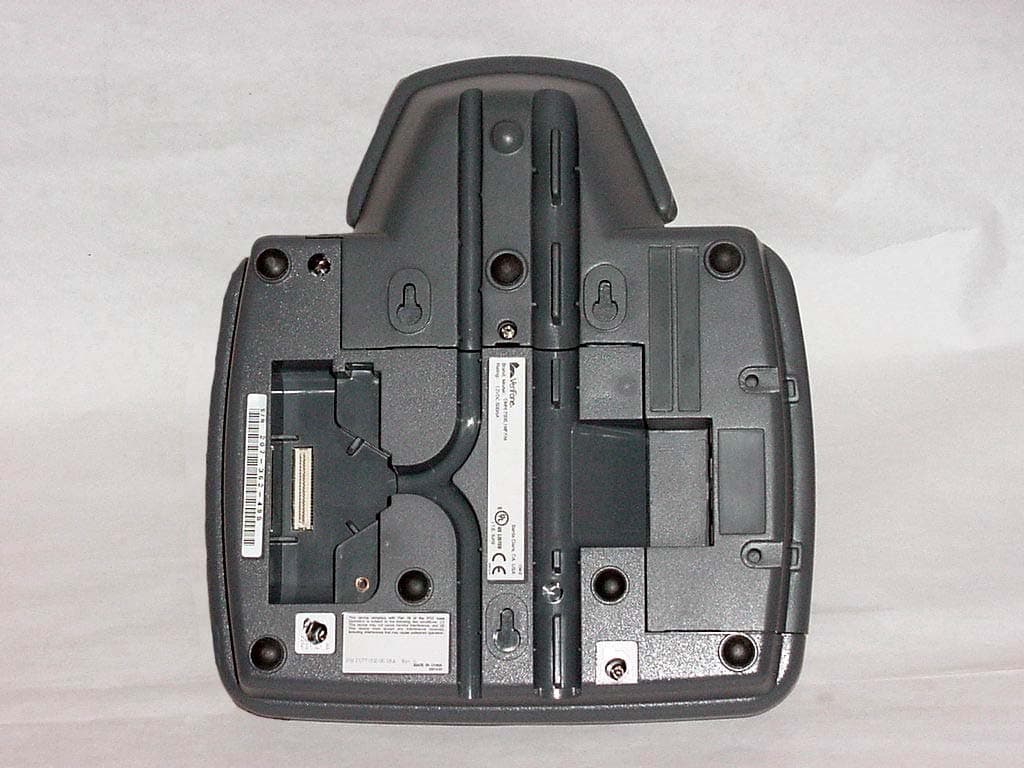
Click to zoom
Application Details
- Equipment Class
- DXX - Part 15 Low Power Communication Device Transmitter
- Date of Grant
- Jul 28, 2004
- Application Purpose
- Original Equipment
- Date of Application
- Jul 28, 2004
- Equipment Note
- CREDITCARD VERIFICATION SYSTEM
- Frequency Range
- 13.55300000 - 13.56700000
- Company
- VeriFone Inc
- Country
- United States
Documents & Files
Document Text
Text extracted from the exhibit documents filed with the FCC. Open a document above to read the original.
Users Manual
pay TM OEM ViVOtech Corporate Headquarters451 El Camino Real, Santa Clara, CA 95050. Phone: (408) 248 7001 www.vivotech.com Version 1.0 April 2004 Copyright 2004 ViVOtech, Inc. FCC Regulatory Compliance: Notices Class B Equipment: This equipment has been tested and found to comply with the limits for a Class B digital device, pursuant to part 15 of the FCC Rules. These limits are designed to provide reasonable protection against harmful interference in a residential installation. This equipment generates, uses and can radiate radio frequency energy and, if not installed and used in accordance with the instructions, may cause harmful interference to radio communications. However, there is no guarantee that interference will not occur in a particular installation. T his device complies with part 15 of the FCC Rules. Operation is subject to the following two conditions: (1) This device may not cause harmful interference, and (2) this device must accept any interference received, including interference that may cause undesired operation. * ViVOtech, ViVOpay, ViVOpay OEM are trademarks or registered trademarks of ViVOtech Corporation. VeriFone and OMNI are trademarks or registered trademarks of VeriFone Corporation. All other trademarks or brand names are the properties of their respective holders. Features and specifications are subject to change without notice. ! WARNING: 1.The ViVOpay hardware or software can not be replaced or modified by any third party other than VIVOtech.2. Minimum separation distance between 2 ViVOpay devices should be at least 2 feet.3.The device should be mounted and seated on a non metal surface and be at least 6 inches far from any metal surface . For VeriFone ® OMNI ® 7000 USER GUIDE ViVOpay OEM USER GUIDE The ViVOpay OEM module is equipped with 2 LEDs on the top to provide consumers feedback on the read process. Further feedback is given by the VeriFone OMNI 7000 POS system. Idle: Just first LED is ON. Read SUCCESS: 2nd LED ON and beep from the VeriFone OMNI 7000 device. 3. The ViVOpay OEM antenna quickly reads the information from the card through RF technology - no physical contact is necessary. In a fraction of a second the reader validates the card, and secures the transaction.4. ViVOpays OEM module automatically sends the information to the VeriFone OMNI 7000 POS.5. The VeriFone OMNI 7000 POS displays the card data and the clerk proceeds to approve the transaction and print the receipt, which the clerk gives to the consumer for signature as with any other purchase. Consumers just need to hold their Paypass devices in front of the ViVOpay The merchant operation of the ViVOpay OEM module is very simple and almost entirely driven by the VeriFone OMNI 7000 POS. Once installed, the clerk's role on the operation of the system is simply to guide new customers to hold their contactless RF-enabled cell phones, plastic cards or key chains in front of the ViVOpay OEM reader module. The information is automatically transferred to the VeriFone OMNI 7000 POS system and processed in the same way a standard magnetic card would be. Typical Usage ViVOtech Corporate Headquarters451 El Camino Real, Santa Clara, CA 95050. Phone: (408) 248 7001 Audio-Visual Feedback How it Works Contactless devices can have innumerous form factors as cell phone covers, plastic cards and key chains, enabled with RF tags that securely release the payment information to the ViVOpay OEM module without the need of physical contact with the Point of Sale terminal using contactless technology. The ViVOpay OEM module is constantly emitting a magnetic field, when it detects an RF tag in the field, it communicates with it and retrieves the payment information. The card information is then transmitted to the VeriFone OMNI 7000 POS device via data packets on a serial connection with the VeriFone POS device. www.vivotech.com 1. The customer approaches the clerk with one or more items to purchase. The clerk enters the total value into the OMNI 7000, asks the consumer for the form of payment, and mentions the contactless payment option by pointing to the ViVOpay OEM module on top of the OMNI 7000.2. The consumer pulls his or her contactless device and holds it in front of the ViVOpay OEM antenna. The card number will appear in the VeriFone OMNI 7000 LCD screen.
Cover Letter(s)
VeriFone Inc. 3755 Atherton Road Rocklin, CA 95765-3701 Tel: 916/630-0550 Fax: 916/630-2501 Date: Tuesday, April 13, 2004 Federal Communication Commission Office of Engineering Technology Equipment Authorization Division Subject: Application for Equipment Authorization, FCC ID: B32OMNI7KRFID To Whom It May Concern: Pursuant to section 0.459 of 47 CFR, confidentiality is requested for: schematics , block diagram, bill of material (BOM) and the theory of operation for the Omni 7xxx product FCC ID B32OMNI7KRFID. Justification for this request is the protection of proprietary trade secrets and that such materials would customarily be guarded from competitors. Fees for the requested confidentiality has been paid as a part of the overall remittance. Sincerely, Technical Staff Senior EMC Engineer William Morse NCE Phone 916.630.2540 FAX 916.630.2501 EMAIL [email protected]
Test Report
TIMCO ENGINEERING INC. 849 NW State Road 45 Newberry, Florida 32669 http://www.timcoengr.com 888.472.2424 F 352.472.2030 email: [email protected] APPLICANT: VERIFONE FCC ID: B32OMNI7KRFID REPORT #: V\VERIFONE\645DUT\645DUT4TestReport.doc COVER PAGE Test Report Product Name: CREDITCARD VERIFICATION SYSTEM FCC ID: B32OMNI7KRFID Applicant: VERIFONE 3755 ATHERTON ROAD ROCKLIN CA 95765 Date Receipt: MAY 6, 2004 Date Tested: MAY 26, 2004 TIMCO ENGINEERING INC. 849 NW State Road 45 Newberry, Florida 32669 http://www.timcoengr.com 888.472.2424 F 352.472.2030 email: [email protected] APPLICANT: VERIFONE FCC ID: B32OMNI7KRFID REPORT #: V\VERIFONE\645DUT\645DUT4TestReport.doc TABLE OF CONTENTS TABLE OF CONTENTS APPLICANT: VERIFONE FCC ID : B32OMNI7KRFID TEST REPORT CONTAINING: PAGE 1...............TEST EQUIPMENT LIST PAGE 2...............TEST PROCEDURE PAGE 3-5.............RADIATION INTERFERENCE TEST DATA PAGE 6-10............POWER LINE CONDUCTED TEST DATA PAGE 11..............OCCUPIED BANDWIDTH PAGE 12..............OCCUPIED BANDWIDTH PLOT PAGE 13..............FREQUENCY STABILITY TEST DATA EXHIBITS INCLUDING: REQUEST FOR CONFIDENTIALITY LETTER BLOCK DIAGRAM SCHEMATICS USERS MANUAL LABEL SAMPLE LABEL LOCATION EXTERNAL PHOTOGRAPHS INTERNAL PHOTOGRAPHS CIRCUIT DESCRIPTION PARTS LIST TEST SET UP PHOTOGRAPH TIMCO ENGINEERING INC. 849 NW State Road 45 Newberry, Florida 32669 http://www.timcoengr.com 888.472.2424 F 352.472.2030 email: [email protected] APPLICANT: VERIFONE FCC ID: B32OMNI7KRFID REPORT #: V\VERIFONE\645DUT\645DUT4TestReport.doc Page 1 of 13 EMC Equipment List Device Manufacturer Model Serial Number Cal/Char Date Due Date 3/10-Meter OATS TEI N/A N/A Listed 3/27/04 3/26/07 3-Meter OATS TEI N/A N/A Listed 1/13/03 1/13/06 Biconnical Antenna Eaton 94455-1 1057 CAL 3/18/03 3/18/05 Biconnical Antenna Eaton 94455-1 1096 CAL 10/1/01 10/1/03 Biconnical Antenna Electro- Metrics BIA-25 1171 CAL 4/26/01 4/26/03 Blue Tower Quasi-Peak Adapter HP 85650A 2811A01279 CAL 4/15/03 4/15/05 Blue Tower RF Preselector HP 85685A 2620A00294 out for Cal Blue Tower Spectrum Analyzer HP 8568B 2928A04729 2848A18049 CAL 4/15/03 4/15/05 LISN Electro- Metrics ANS-25/2 2604 CAL 10/9/01 10/9/03 LISN Electro- Metrics EM-7820 2682 CAL 3/12/03 3/12/05 Log- Periodic Antenna Eaton 96005 1243 CAL 5/8/03 5/8/05 TIMCO ENGINEERING INC. 849 NW State Road 45 Newberry, Florida 32669 http://www.timcoengr.com 888.472.2424 F 352.472.2030 email: [email protected] APPLICANT: VERIFONE FCC ID: B32OMNI7KRFID REPORT #: V\VERIFONE\645DUT\645DUT4TestReport.doc Page 2 of 13 TEST PROCEDURES GENERAL: This report shall NOT be reproduced except in full without the written approval of TIMCO ENGINEERING, INC. RADIATION INTERFERENCE: The test procedure used was ANSI STANDARD C63.4-2001 using a HEWLETT PACKARD spectrum analyzer with a pre-selector. In the frequency range 10 kHz to 30 MHz the RBW was 10 kHz and from 30-1000 MHz the RBW of the spectrum analyzer was 100 kHz with an appropriate sweep speed. The analyzer was calibrated in dB above a microvolt at the output of the antenna. The resolution bandwidth was 100 kHz and the video bandwidth was 300 kHz. The ambient temperature of the UUT was 80º with a humidity of 42%. FORMULA OF CONVERSION FACTORS: The Field Strength at 3m was established by adding the meter reading of the spectrum analyzer (which is set to read in units of dBuV) to the antenna correction factor supplied by the antenna manufacturer. The antenna correction factors are stated in terms of dB. The gain of the Preselector was accounted for in the Spectrum Analyzer Meter Reading. Example: Freq (MHz) METER READING + ACF = FS 33 20 dBuV + 10.36 dB = 30.36 dBuV/m @ 3m ANSI C63.4-1992 Section 8.2.1 MEASUREMENT PROCEDURES: The EUT was placed on a non-conducting table 80 cm above the ground plane with the EUT located in the center of the table. With the antenna vertical a preliminary scan was done at 1 meters distance, the EUT was moved to a 3.0-meter distance and the antenna height varied and also placed in a horizontal position. The frequency was scanned from 9.0 kHz to 1.0 GHz. When an emission was found, the table was rotated to produce the maximum signal strength. The EUT was measured in three (3) orthogonal planes. The unit was measured at TIMCO ENGINEERING, INC. located at 849 N.W. State Road 45 Newberry, Florida 32669. TIMCO ENGINEERING INC. 849 NW State Road 45 Newberry, Florida 32669 http://www.timcoengr.com 888.472.2424 F 352.472.2030 email: [email protected] APPLICANT: VERIFONE FCC ID: B32OMNI7KRFID REPORT #: V\VERIFONE\645DUT\645DUT4TestReport.doc Page 3 of 13 APPLICANT: VERIFONE FCC ID: B32OMNI7KRFID NAME OF TEST: RADIATION INTERFERENCE RULES PART NO: 15.225 and 15.209 REQUIREMENTS: THE FIELD STRENGTH OF ANY EMISSION WITHIN THE BAND OF 13.553-13.57 MHz SHALL NOT EXCEEDS 10,000 uV/m (80 dBuV/m) AT 30 METERS. THE FIELD STRENGTH OF ANY EMISSIONS APPEARING OUTSIDE OF THIS BAND SHALL NOT EXCEED THE GENERAL RADIATED EMISSION LIMITS SHOWN IN §15.209. 9 to 490 KHz: 2400/F (kHz) uV/m @ 300 METERS 490 to 1705 KHz: 24000/F (kHz) uV/m @ 30 METERS 1705 to 30 MHz: 29.54 dBuV/M @ 30 METERS 30 to 88 MHz: 40.00 dBuV/M @ 3 METERS 88 to 216 MHz: 43.50 dBuV/M 216 to 960 MHz: 46.02 dBuV/M ABOVE 960 MHz: 54.00 dBuV/M TEST DATA: 13.56 12 H 0 35.52 47.52 72.48 Emission Frequency MHz Meter Reading dBuV Ant. Polarity Coax Loss dB Correction Factor dB Field Strength dBuV/m Margin dB 57.56 17.5 V 0.53 11.34 29.37 10.63 57.80 12.0 H 0.53 11.32 23.85 16.15 60.00 14.1 H 0.53 11.10 25.73 14.27 60.02 22.4 V 0.53 10.79 33.72 6.28 80.02 12.8 H 0.60 6.30 19.70 20.30 80.02 18.4 V 0.60 7.31 26.31 13.69 94.95 13.3 V 0.64 10.69 24.63 18.87 94.95 16.0 H 0.64 9.49 26.13 17.37 99.53 17.4 H 0.65 11.13 29.18 14.32 100.00 17.2 H 0.65 11.30 29.15 14.35 100.83 16.7 H 0.65 11.40 28.75 14.75 120.00 15.3 V 0.67 13.70 29.67 13.83 120.00 17.9 H 0.67 13.40 31.97 11.53 160.00 17.0 V 0.74 15.50 33.24 10.26 160.00 19.1 H 0.74 14.30 34.14 9.36 200.00 26.1 V 0.90 12.00 39.00 4.50 200.00 30.6 …
Text truncated - open the document above for the full version.
Contact Information
Applicant
Kenji Chao(Sr. Director, Hardware Engineering)
Test Firm
Timco Engineering, Inc.Sid Sanders
Technical Specifications
| # | Rule Parts | Frequency Range | Power Output |
|---|---|---|---|
| 1 | 15C | 13.553 MHz - 13.567 MHz | - |
Other Applications from VeriFone Inc
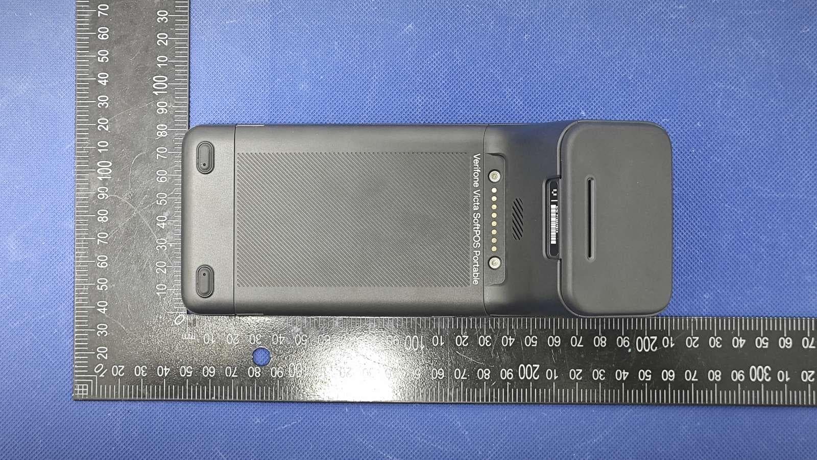
B32VS100P
Jun 22, 2026Point of Sale Terminal
Equipment Class
DXX - Part 15 Low Power Communication Device Transmitter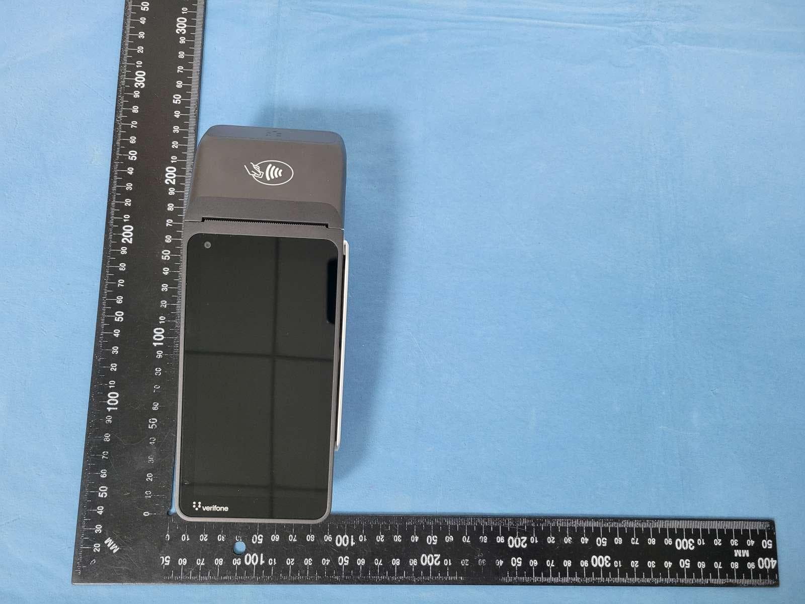
B32V660CA2
Apr 20, 2026Point of Sale Terminal
Equipment Class
NII - Unlicensed National Information Infrastructure TX
B32VM110R
Mar 31, 2026Point of Sale Terminal
Equipment Class
PCB - PCS Licensed Transmitter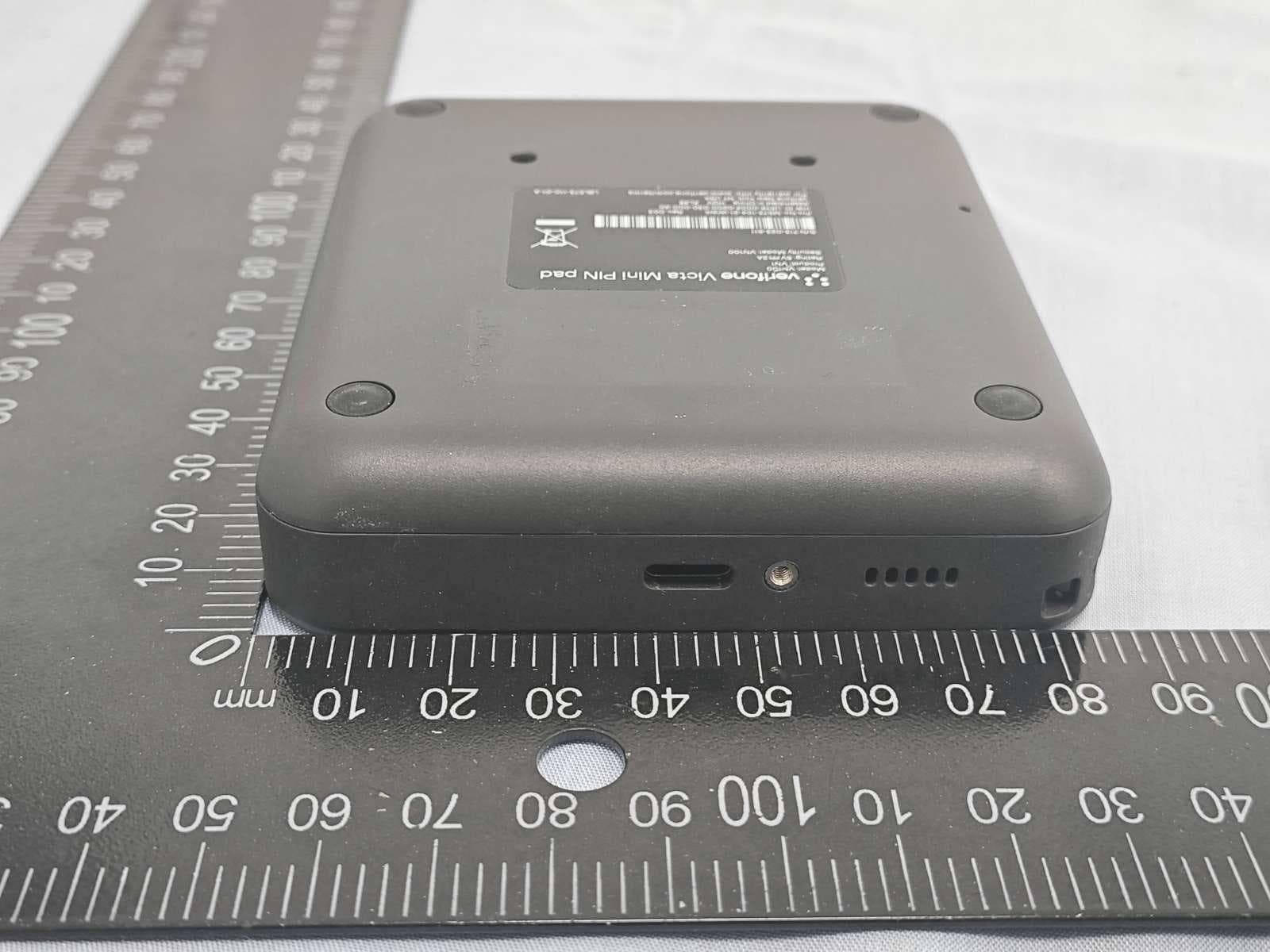
B32VN100
Feb 02, 2026Point of Sale Terminal
Equipment Class
DXX - Part 15 Low Power Communication Device Transmitter
B32VS100M
Dec 03, 2025Point of Sale Terminal
Equipment Class
PCE - PCS Licensed Transmitter held to ear