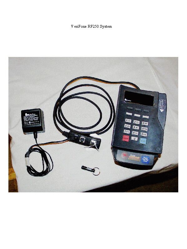
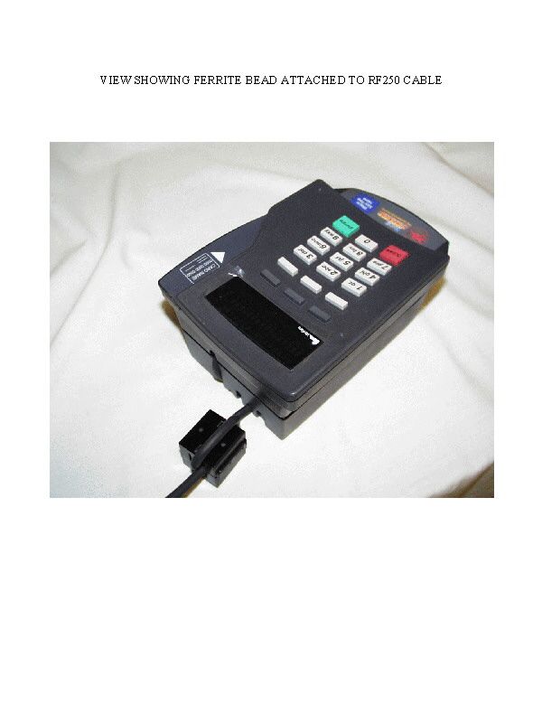
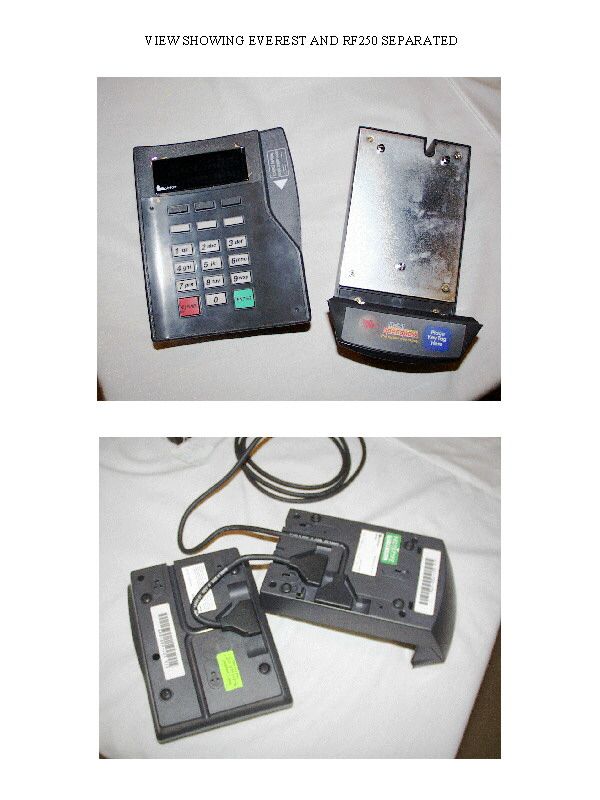
B32RF250RFID device that is part of a point of sale termin
VeriFone Inc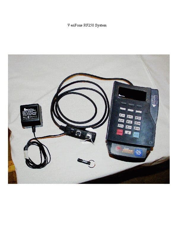
Click to zoom
Application Details
- Equipment Class
- DCD - Part 15 Low Power Transmitter Below 1705 kHz
- Date of Grant
- Mar 15, 1999
- Application Purpose
- Original Equipment
- Date of Application
- Jan 11, 1999
- Equipment Note
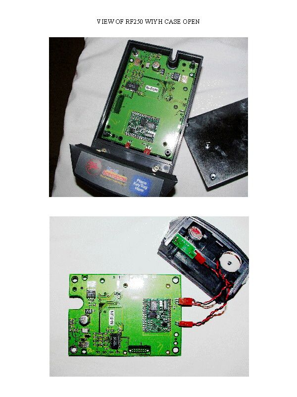
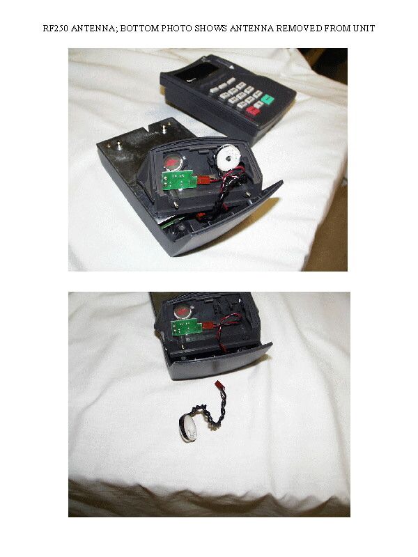
- RFID device that is part of a point of sale termin
- Frequency Range
- 0.13400000 - 0.13400000
- Company
- VeriFone Inc
- Country
- United States
Documents & Files
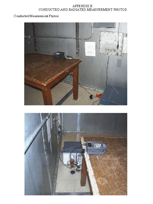
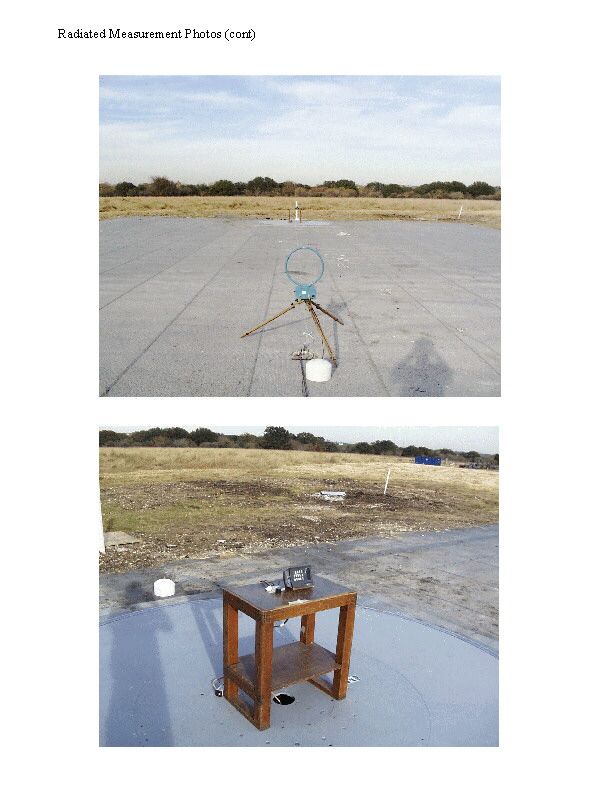
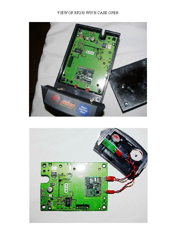
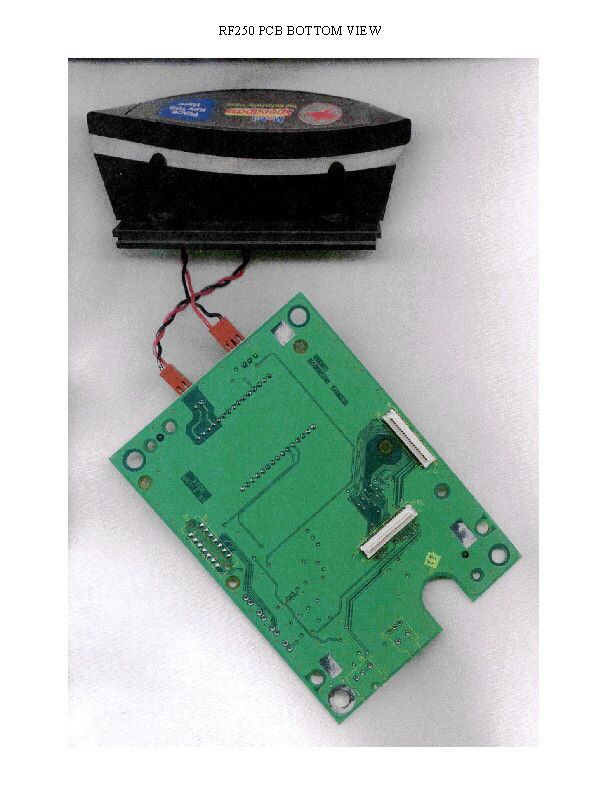
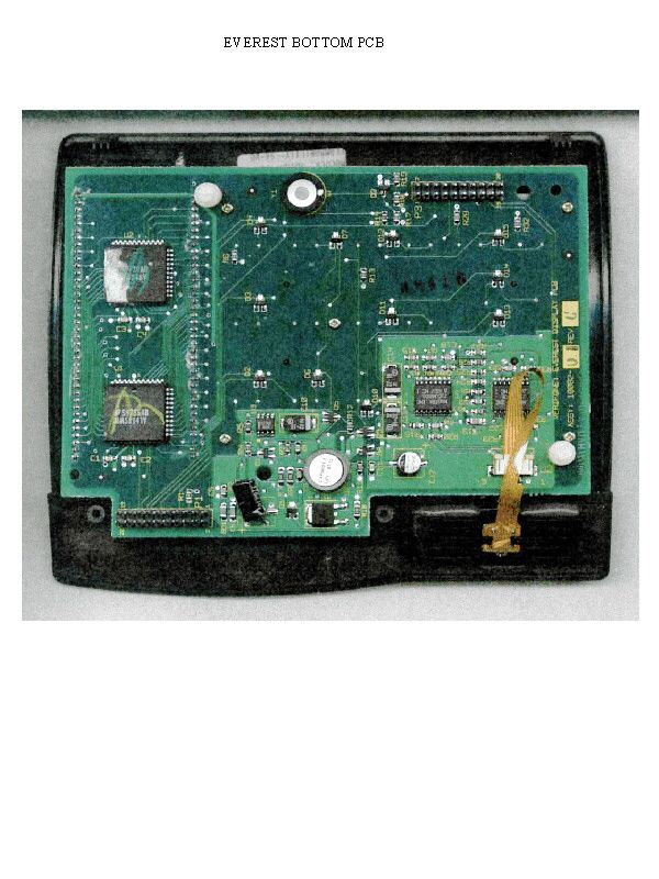
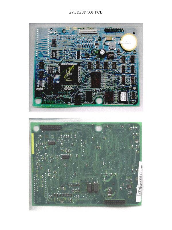
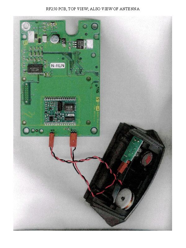
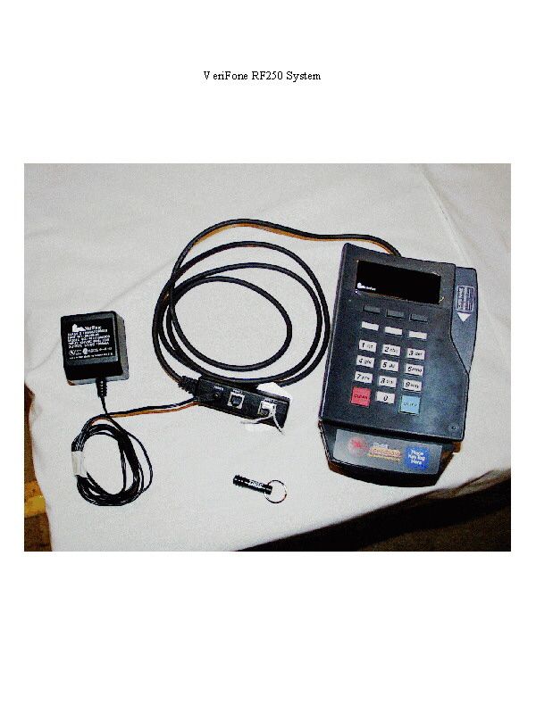
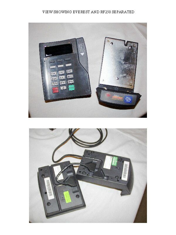
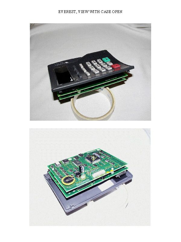
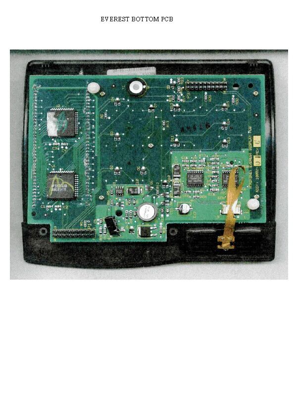
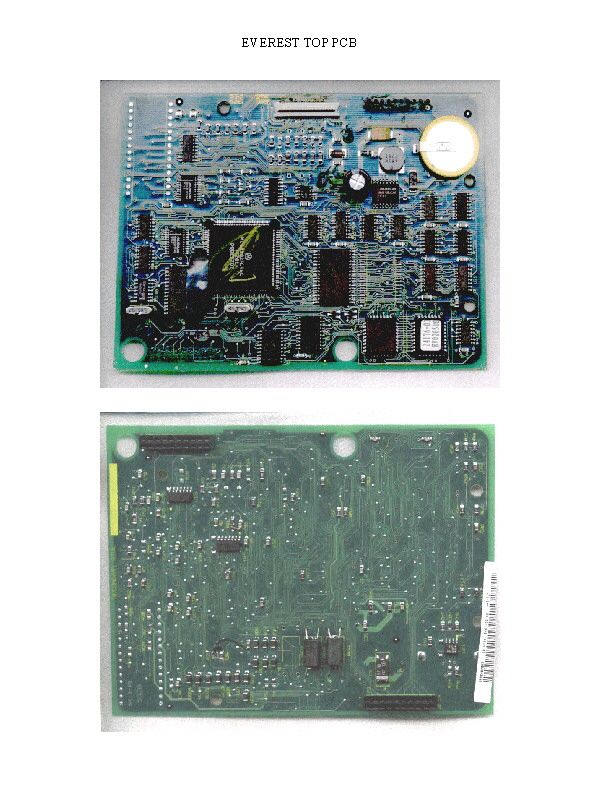
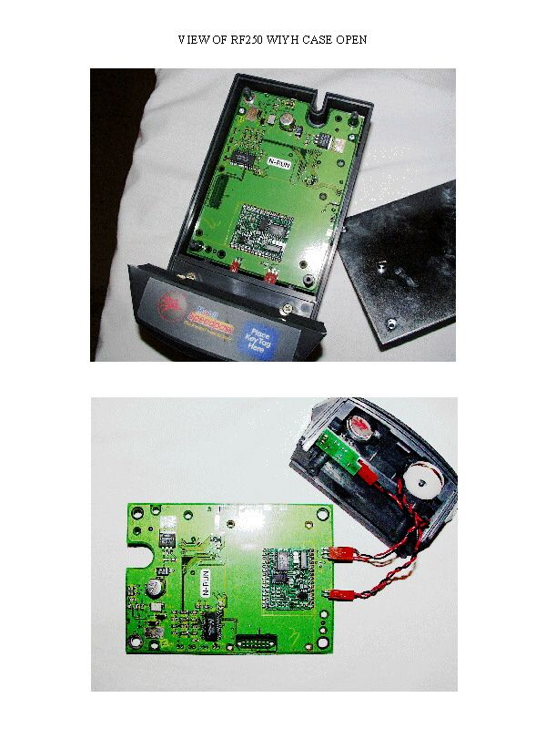
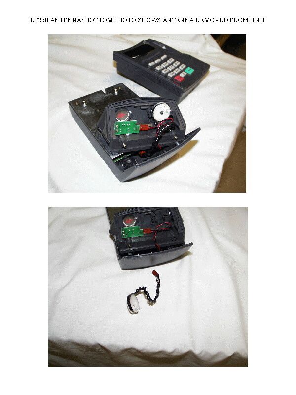
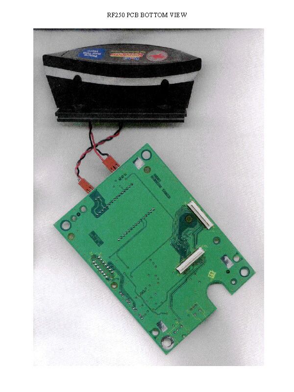
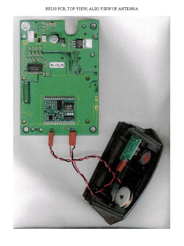
Document Text
Text extracted from the exhibit documents filed with the FCC. Open a document above to read the original.
Users Manual
Mobil Indoor Speedpass Installation Guide P/N: 55225 Revision A Mobil Indoor Speedpass Installation Guide September 11, 1998 VeriFone ® , Inc. 4988 Great America Parkway Santa Clara, CA 95054-1200 Telephone: 408-496-0444 http://www.verifone.com Printed in the United States of America. © 1998 by VeriFone, Inc. All rights reserved. No part of this publication covered by the copyrights herein may be reproduced or copied in any form or by any means — graphic, electronic, or mechanical, including photocopying, taping, or information storage and retrieval systems — without written permission of the publisher. The content of this document is subject to change without notice. The information contained herein does not represent a commitment on the part of VeriFone, Inc. Publications are not stocked at the address given above. Requests for VeriFone publications should be made to your VeriFone representative. VeriFone is a registered trademark of VeriFone, Inc. Speedpass is a trademark of Mobil Oil Corporation. All other products mentioned in this manual are trademarks or registered trademarks of their respective owners. Mobil Indoor Speedpass Installation Guide Revision History RevisionDateComments ASeptember 11, 1998Initial release of software and documentation. FCC Compliance This equipment complies with the requirements in Part 15 of FCC rules for a Class A computing device. Operation of this equipment in a residential area may cause unacceptable interference for radio and TV reception requiring the operator to take whatever steps necessary to correct the interference. Safety Instructions n Read all instructions contained in this guide before making any equipment connections. n Save these instructions for later use. n Unplug the unit before servicing or cleaning. Do not use liquid or aerosol cleaners. Use only a damp cloth for cleaning. n Do not use any attachments not specifically recommended by VeriFone as they may result in the risk of fire, electric shock, or injury to persons. n Do not use the unit near water. n Do not place the unit on an unstable cart, stand, or table. The unit may fall, causing serious personal injury and/or damage to the equipment. Contents u i Contents 1. Introduction . . . . . . . . . . . . . . . . . . . . . . . . . .1 2. Unpacking. . . . . . . . . . . . . . . . . . . . . . . . . . . .3 3. Installation . . . . . . . . . . . . . . . . . . . . . . . . . . .5 Installation Procedures . . . . . . . . . . . . . . . . . . . . . . . . . . . . . . . 5 Equipment Power Up . . . . . . . . . . . . . . . . . . . . . . . . . . . . . . . . 6 4. Specifications. . . . . . . . . . . . . . . . . . . . . . . . .9 Power Requirements . . . . . . . . . . . . . . . . . . . . . . . . . . . . . . . . 9 Operating Environment . . . . . . . . . . . . . . . . . . . . . . . . . . . . . . 9 Service and Repair . . . . . . . . . . . . . . . . . . . . . . . . . . . . . . . . . . 9 Cleaning . . . . . . . . . . . . . . . . . . . . . . . . . . . . . . . . . . . . . . . . . 10 ii u Contents Introduction u 1 1 Introduction This document provides the information necessary to install your Mobil Indoor Speedpass System. The Mobil Indoor Speedpass System is a self-contained device, when properly installed, becomes an integral part of the POS equipment. It has the ability of reading a retail customer’s tag when placed near an antenna mounted on the face of the equipment. nmobilind.wmf 125% Soft Key Guard Card Swipe Guard Multicable Power Supply Mobil Indoor Speedpass 2 u Introduction Information from the tag is processed and transferred to POS equipment. Unpacking u 3 2 Unpacking Carefully inspect the shipping carton and its contents for any damage that may have occurred during shipment. If anything appears damaged, immediately file a claim with the shipping company or carrier and notify the Point of Sales equipment manufacturer. Warning:Never use damaged equipment. A shock or fire hazard may exist if equipment is energized in a damaged condition. Remove the following items from the shipping carton: n Mobil Indoor Speedpass Unit with attached Mulitcable n Power Supply n Soft Key Guard n Card Swipe Guard Remove any protective plastic wrapping from the components and place them on a table or countertop. Retain the shipping carton and any packing material in case it is necessary to move components from one location to another or to return the equipment for service. 4 u Unpacking Installation u 5 3 Installation Unpack equipment in accordance with instructions listed in Chapter 2. Warning:To reduce the risk of fire, do not place this unit near any heat producing source. When selecting a location for your Mobil Indoor Speedpass equipment, avoid areas having: n Direct sunlight or objects that produce heat. n Excessive dust. n Electrical “noise” or devices that cause excessive voltage variations such as air conditioners, fans, or high frequency security systems. Installation Procedures Use the following procedures to install and power up the Mobil Indoor Speedpass. 1.Place the unit close to the POS equipment. 2.Uncoil the Multicable and ensure that it does not kink or is not placed under heavy equipment. 3.Uncoil the Power Supply cable. 4.Mount the unit on a custom stand, if applicable. 6 u Installation 5.Locate the RS232 and RS485 cabling from the POS equipment. 6.Insert the RS232 cable connector into the Multicable jack labeled PORT 1. 7.Insert the RS485 cable connector into the Multicable jack labeled PORT 3. Equipment Power Up Before installing your Mobil Indoor Speedpass equipment, a quality surge protector should be purchased to protect the equipment from voltage surges. Ideally, the Mobil Indoor Speedpass equipment and the POS equipment should have its own dedicated AC power outlet. The surge protector is plugged into the AC power outlet first. The Mobil Indoor Speedpass Power Supply should then be plugged into the surge protector. Use the following procedures to power up the Mobil Indoor Speedpass unit: 1.Insert…
Text truncated - open the document above for the full version.
Cover Letter(s)
A subsidiary of Hewlett-Packard 3755 ATHERTON ROAD ROCKLIN, CALIFORNIA 95765 TEL: (916) 315-1534 FAX: (916) 630-2501 January 13,1999 Federal Communications Commission Equipment Approval Services P.O. Box 358315 Pittsburgh, PA 15251-5315 Enclosed is the remittance for the fee for the equipment certification of B32RF250, which was filed electronically on January 13, 1999 (Form 731 Confirmation Number EA92908). The fee for request of confidentiality is included in the remittance for keeping the schematics, internal photos, and theory of operation confidential to protect proprietary trade secrets. Jeff Brower Electrical Engineer [email protected]
Cover Letter(s)
A subsidiary of Hewlett-Packard 3755 ATHERTON ROAD ROCKLIN, CALIFORNIA 95765 TEL: (916) 315-1534 FAX: (916) 630-2501 March 15,1999 Federal Communications Commission Equipment Approval Services P.O. Box 358315 Pittsburgh, PA 15251-5315 Enclosed is the remittance for the fee for the equipment certification of B32RF250, which was filed electronically on January 13, 1999 (Form 731 Confirmation Number EA92908). The fee for request of confidentiality is included in the remittance for keeping the schematics, and theory of operation confidential to protect proprietary trade secrets. Jeff Brower Electrical Engineer [email protected]
Operational Description
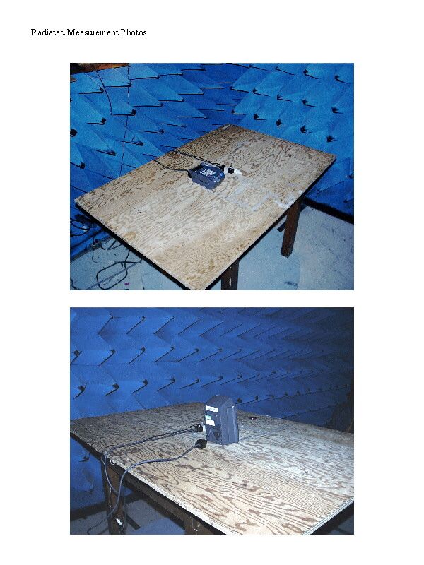
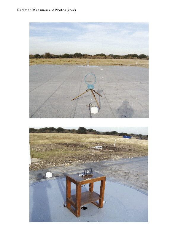
CONDUCTED MEASUREMENT PLOTS RADIATED MEASUREMENT PLOTS
Test Report
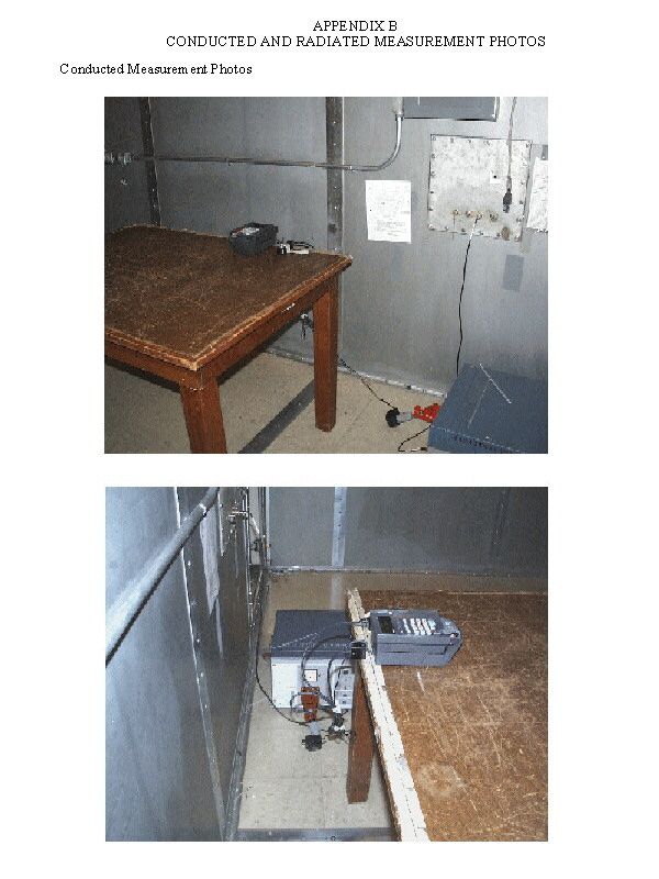
FCC ID: B32RF250 P:\10-2390\001fcr.wpd 1 of 20 MEASUREMENT AND TECHNICAL REPORT ON THE VERIFONE RF250 POINT OF SALE TERMINAL Southwest Research Institute 6220 Culebra Road San Antonio, Texas 78228-0510 Project 10-2390-001 Report Number EMCR 98/100 Prepared for: VeriFone, Inc. 4988 Great America Parkway Santa Clara, CA 95054 Prepared by: David A. Carmony December 1998 The results of this test report apply only to the specific samples tested. If the manufacturer extends the test results to apply to other samples of the same model, or from the same lot or batch, the manufacturer should ensure the additional samples are manufactured using identical electrical and mechanical components. This test report shall not be reproduced, except in full, without the written approval of the Electromagnetic Compatibility Research Section, Southwest Research Institute. Reviewed by:Approved: Ismael Martinez, Jr.James J. Polonis Sr. Engineering TechnologistManager FCC ID: B32RF250 P:\10-2390\001fcr.wpd 2 of 20 Electromagnetic Compatibility Research Section Electromagnetic Compatibility Research Section Communications Engineering DepartmentCommunications Engineering Department FCC ID: B32RF250 P:\10-2390\001fcr.wpd 3 of 20 TABLE OF CONTENTS Page List of Tables ................................................................................................................................................ 3 1.0General Information......................................................................................................................... 4 1.1Product Description ......................................................................................................................... 4 1.2Related Grants ................................................................................................................................. 4 1.3Tested System Details...................................................................................................................... 4 1.4Test Methodology............................................................................................................................ 5 1.5Test Facility ..................................................................................................................................... 5 2.0Product Labeling ............................................................................................................................. 6 2.1FCC ID Label .................................................................................................................................. 6 2.2Location of Label on EUT ............................................................................................................... 6 2.3Supplemental Information to be in the RF250 Manual..................................................................... 6 3.0System Test Configuration .............................................................................................................. 7 3.1Justification ..................................................................................................................................... 7 3.2EUT Exercise ................................................................................................................................ 7 3.3Special Accessories ......................................................................................................................... 7 3.4Equipment Modification.................................................................................................................. 7 3.5 Configuration of Tested System ...................................................................................................... 7 4.0Block Diagram of the RF250 Terminal ............................................................................................ 8 5.0Conducted and Radiated Measurement Photos................................................................................ 9 6.0Conducted Emission Data ............................................................................................................. 10 6.1Conducted Measurement Data....................................................................................................... 10 6.2Conducted Test Instrumentation ................................................................................................... 10 7.0Radiated Emission Data................................................................................................................. 11 7.1Radiated Measurement Data.......................................................................................................... 11 7.2Test Instrumentation for Radiated Measurements ......................................................................... 14 7.3Field Strength Calculation ............................................................................................................. 14 8.0Photos of Tested EUT ................................................................................................................... 15 Appendix A: Conducted and Radiated Signature Measurement Plots....................................................... 16 Appendix B: Conducted and Radiated Measurement Photos .................................................................... 17 Appendix C: Test Instrumentation............................................................................................................. 18 Appendix D: Photos of Tested EUT .......................................................................................................... 20 Attachment 1: Technical Description and Block Diagram Attachment 2: Installation Guide Attachment 3: Technical Documentation FCC ID: B32RF250 P:\10-2390\001fcr.wpd 4 of 20 LIST OF TABLES TablePage 1.1RF250 Terminal Components .......................................................................................................... 4 7.1Measurements of Fundamental Freq…
Text truncated - open the document above for the full version.
Contact Information
Applicant
Kenji Chao(Sr. Director, Hardware Engineering)
Technical Contact
VeriFone, IncJeff Brower
[email protected]916-630-1534
3755 Atherton Road · Rocklin, California · United States
Test Firm
Southwest Research InstituteDavid Carmony
210-684-5111
Technical Specifications
| # | Rule Parts | Frequency Range | Power Output |
|---|---|---|---|
| 1 | 15C | 0.134 MHz - 0.134 MHz | - |
Other Applications from VeriFone Inc
B32VS100P
Jun 22, 2026Point of Sale Terminal
Equipment Class
DXX - Part 15 Low Power Communication Device Transmitter
B32V660CA2
Apr 20, 2026Point of Sale Terminal
Equipment Class
NII - Unlicensed National Information Infrastructure TX
B32VM110R
Mar 31, 2026Point of Sale Terminal
Equipment Class
PCB - PCS Licensed Transmitter
B32VN100
Feb 02, 2026Point of Sale Terminal
Equipment Class
DXX - Part 15 Low Power Communication Device Transmitter
B32VS100M
Dec 03, 2025Point of Sale Terminal
Equipment Class
PCE - PCS Licensed Transmitter held to ear