B32VX670BTVx670 Bluetooth
VeriFone Inc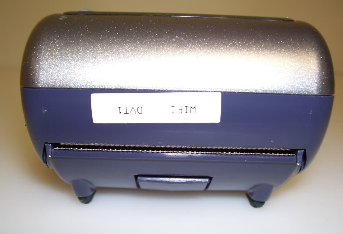
Click to zoom
Application Details
- Equipment Class
- DSS - Part 15 Spread Spectrum Transmitter
- Date of Grant
- Oct 18, 2007
- Application Purpose
- Original Equipment
- Date of Application
- Oct 18, 2007
- Equipment Note
- Vx670 Bluetooth
- Frequency Range
- 2402.00000000 - 2480.00000000
- Company
- VeriFone Inc
- Country
- United States
Documents & Files
Document Text
Text extracted from the exhibit documents filed with the FCC. Open a document above to read the original.
Users Manual
c 2007 VeriFone, Inc. All rights reserved. 2099 Gateway Place, Suite 600 San Jose CA 95110 Tel: 800 VeriFone (837-4366) www.verifone.com V x 670 Certifications and Regulations VeriFone Part Number: 24000 Revision C *24000* continued on rear coverElectricalPower PacksBefore you connect the terminal power pack to an electrical outlet, check that the on/off power switch on the terminal is off. If the terminal does not have an on/off switch, check that the power cable connector is removed from the terminal’s power port.or When connecting the terminal to a power pack, always connect the plug of the power pack to an electrical wall outlet first . Then connect the power cable to the terminal’s power port.The power pack is rated as follows:Input Voltage: 100 - 240 V AC, 50/60 HzOutput Voltage: 12 V DC, 2 A AC AdapterThe AC adapter is designed to ensure your personal safety and to be compatible with this equipment. Please follow these guideli nes: • Do not use the adapter in a high moisture environment. Never touch the adapter when your hands or feet are wet. • Allow adequate ventilation around the adapter. Avoid locations with restricted airflow. • Connect the adapter to a proper power source. The voltage and grounding requirements are found on the product case and/or packaging. • Do not use the adapter if the cord becomes damaged. • Do not attempt to service the adapter. There are no serviceable parts inside. Replace the unit if it is damaged or exposed to excess moisture. Separate Power SourcesSome peripherals require a separate power source. Before connecting a check reader or similar device, remove the power cable connector from the terminal’s power port. PeripheralsBefore connecting any peripheral device, turn off power to the terminal and check that the power cable connector is removed from the terminal’s power port. Turn on power only after you are finished connecting the peripheral device(s). For complete information about peripheral installation and use, please refer to the user documentation supplied with those devices. Telecommunication CordCaution: To reduce the risk of fire, use only No. 26 AWG or larger UL Listed or CSA Certified Telecommunication Line Cord.Disconnecting PowerDisconnecting power during a transaction may cause transaction data files that are not yet stored in terminal memory to be lost. Location – Electrical ConsiderationsCAUTION : Due to risk of electrical shock or terminal damage, do not use the terminal near water, including a bathtub, wash bowl, kitch en sink or laundry tub, in a wet basement, or near a swimming pool. Also, avoid using this product during electrical storms.Avoid locations near electrical appliances or other devices that cause excessive voltage fluctuations or emit electrical noise (for example, air conditioners, neon signs, high-frequency or magnetic security devices, or electric motors). EquipmentRepairsDo not, under any circumstances , attempt any service, adjustments, or repairs on this equipment. Instead, contact your local VeriFone distributor or service provider for assistance. Failure to comply may void the product warranty. Location – Environmental ConsiderationsDo not plug the power pack into an outdoor outlet or operate the terminal outdoors. It is not waterproof or dustproof, and is f or indoor use only. Any damage to the unit from exposure to rain or dust may void your warranty.Do not use the terminal where there is high heat, dust, humidity, moisture, or caustic chemicals or oils. Keep the terminal awa y from direct sunlight and anything that radiates heat, such as a stove or a motor. Battery Pack InstructionsDispose of the battery pack in accordance with all national, state, and local laws and regulations as regionally required. Some batteries V x 670 Certifications and Regulations FCC ComplianceThe following device has been tested and certified as compliant with the regulations and guidelines set forth in Part 68 of FCC Rules:Manufacturer: VeriFone, Inc.Brand, Model: V x 670 Part 15 of FCC RulesThis device complies with Part 15 of the FCC Rules. Operation is subject to the following two conditions: 1 this device may not cause harmful interference, and 2 this device must accept any interference received, including interference that may cause undesired operation. This equipment has been tested and found to comply with the limits for a Class B digital device, pursuant to part 15 of the FCC Rules. These limits are designed to provide reasonable protection against harmful interference in a residential installation. T his equipment generates, uses and can radiate radio frequency energy and, if not installed and used in accordance with the instructions, may cause harmful interference to radio communications. However, there is no guarantee that interference will not occur in a particular installation. If this equipment does cause harmful interference to radio or television reception, which c an be determined by turning the equipment off and on, the user is encouraged to try to correct the interference by one or more of the following measures:• Reorient or relocate the receiving antenna. • Increase the separation between the equipment and receiver. • Connect the equipment into an outlet on a circuit different from that to which the receiver is connected. • Consult the dealer or an experienced radio/TV technician for help. Caution: changes or modifications not expressly approved by the party responsible for compliance could void yout authority to operate this equipment. Part 68 of FCC RulesThis equipment complies with Part 68 of the FCC Rules. On the modem board inside full featured base stations is a label that contains, among other information, the FCC registration number and ringer equivalence number (REN) for this equipment. If requested, this information may be provided to the telephone company.The REN is used to determine the quantity of devices that may be connected to the telephone line. Excessive RENs on the telephone line may resu…
Text truncated - open the document above for the full version.
ID Label/Location Info
REVISIONS DESCRIPTIONREVDATEAPPR UNLESS OTHERWISE SPECIFIED DIMENSIONS ARE IN MILLIMETERS. SIGNATURESDATE SIZE TITLE REVDWG NUMBER A OWNERSHIP SITE: SCALE: DWN ENG CHK SHEET OF THIS DOCUMENT IS THE PROPERTY OF VERIFONE, AND CONTAINS VERIFONE'S CONFIDENTIAL AND PROPRIETARY INFORMATION. IN CONSIDERATION OF VERIFONE'S DISCLOSURE OF THIS DOCUMENT TO YOU, YOU AGREE THAT NEITHER IT NOR THE INFORMATION CONTAINED THEREIN SHALL BE DISCLOSED TO OTHERS OR DUPLICATED, IN WHOLE OR IN PART, OR USED FOR ANY PURPOSES OTHER THAN AGREED TO BY VERIFONE WITHOUT THE EXPRESS WRITTEN CONSENT OF VERIFONE. THIS ARTWORK IS THE PROPERTY OF VERIFONE. HANDLE PHYSICAL ARTWORK WITH CARE AND RETURN TO VERIFONE AS SOON AS POSSIBLE. Actual Size 100%200% 10/17/07A. BHATT. A. BHATT10/17/07 S. RUCKER10/17/07 24076-11-F A/W, LABEL, PROD ID BLUETOOTH, US, VX670 A 1 1 SMFAS NOTED A ECO# C20261 10-OCT-07 SJR MODEL:VX670-B RATING:12VDC, 2A P/N:????-???-??-??? REV:? FCC ID:B32VX670BT IC:787C-VX670BT MADE IN CHINA SHI 24076-11 NOTES: 1. BACKGROUND COLOR: WHITE, TEXT AND LOGO COLOR: BLACK 2. FONT: 1.3MM TALL, 1.8MM LINE SPACE, ZPL FONT C UNLESS OTHERWISE SPECIFIED 3 PRINT CURRENT JOB PART NUMBER. 4 PRINT CURRENT PART NUMBER REVISION. 5. REFERENCE BITMAPS: VFI-LOGO_3-5MM.BMP, SANJOSE_1-5MM.BMP, UL_5MM_ITE8J09-H.BMP, FCC-B_5MM.BMP, CTICK_5MM.BMP 6. ITEMS MARKED Δ HAVE CHANGED PER THIS REVISION. MODEL:VX670-B RATING:12VDC, 2A P/N:????-???-??-??? REV:? FCC ID:B32VX670BT IC:787C-VX670BT MADE IN CHINA SHI 24076-11 4 3 39 REF 22.5 REF .
Test Report
ETC Report No. : 07-05-MAS-116-01 Sheet 1 of 36 Sheets FCC ID: PI403B Rev. No 1.0 CONFORMANCE TEST REPORT FOR FCC 47 CFR, Part 15 Subpart C ( (( (Class II Permissive Change) )) ) Report No.: 07-05-MAS-116-01 Client: Ezurio Limited. Product: Embedded Surface Mount Bluetooth Module Model: TRBLU24-00100 FCC ID: PI403B Manufacturer/supplier: Sanmina SCI Date test item received: 2007/05/15 Date test campaign completed: 2007/06/12 Date of issue: 2007/06/12 The test result only corresponds to the tested sample. It is not permitted to copy this report, in part or in full, without the permission of the test laboratory. Total number of pages of this test report: 36 pages Total number of pages of photos: External photos 1 pages Internal photos 2 pages Setup photos 3 pages Test Engineer Checked By Approved By James James Joe Hsieh ELECTRONICS TESTING CENTER, TAIWAN NO.8, LANE 29, WENMING RD., LESHAN TSUEN, GUISHAN SHIANG, TAOYUAN COUNTY, TAIWAN 33383, R.O.C.TAIWAN, R.O.C. TEL: (03) 3276170~4 INT: +886-3-3276170~4 FAX: (03) 3276188 INT: +886-3-3276188 ETC Report No. : 07-05-MAS-116-01 Sheet 2 of 36 Sheets FCC ID: PI403B Rev. No 1.0 Client : Ezurio Limited. Address : Saturn House, Mercury Park, Wycombe Lane, Wooburn Green HP10 0HH UK Manufacturer : Sanmina SCI Address : 90 MOO 1 TIWANON RD BANMAI, MUNAG PATHUMTHANI 12000 Thailand EUT : Embedded Surface Mount Bluetooth Module Trade name : EZURiO Model No. : TRBLU24-00100 Comment issues : (1) The report also apply to model: TRBLU24-00200、TRBLU24-00300、 TRBLU24-00400、BISMS02BI (2) The multiple listing recognized without test basis is according to information supplied by manufacturer. A detail documentation of the above models must be verified by legal right organization for the EMC characteristic with relation to the subject model. Power Source : Power from USB cable (5.0Vdc) Regulations applied : FCC 47 CFR, Part 15 Subpart C (2006) The testing described in this report has been carried out to the best of our knowledge and ability, and our responsibility is limited to the exercise of reasonable care. This certification is not intended to believe the sellers from their legal and/or contractual obligations. The compliance test is only certified for the test equipment and the results of the testing report relate only to the item tested. The compliance test of this report was conducted in accordance with the appropriate standards. It’s not intention to assure the quality and performance of the product. This report shall not be reproduced except in full, without the approval of ETC. This report must not be used by the client to claim product endorsement by NVLAP or any agency of the U.S. Government. Laboratory Introduction: Electronics Testing Center, Taiwan is recognized, filed and mutual recognition arrangement as following: 1 ISO9001: TüV Product Service 2 ISO/IEC 17025: BSMI, CNLA, DGT, NVLAP, CCIBLAC, UL, Compliance 3 Filing: FCC, Industry Canada, VCCI 4 MRA: Australia, Hong Kong, New Zealand, Singapore, USA, Japan, Korea, China, APLAC through CNLA 5 FCC Registration Number: 90588, 91094, 91095 NVLAP Lab Code 200133-0 ETC Report No. : 07-05-MAS-116-01 Sheet 3 of 36 Sheets FCC ID: PI403B Rev. No 1.0 Table of Contents Page 1 GENERAL INFORMATION .............................................................................................................. 5 1.1 Product Description..............................................................................................................................5 1.2 Characteristics of Device .....................................................................................................................5 1.3 Test Methodology ................................................................................................................................5 1.4 Modifiction List of EUT ......................................................................................................................5 1.5 Test Facility..........................................................................................................................................5 2 PROVISIONS APPLICABLE ............................................................................................................. 6 2.1 Definition .............................................................................................................................................6 2.2 Requirement for Compliance...............................................................................................................7 2.3 Restricted Bands of Operation .............................................................................................................9 2.4 Labeling Requirement..........................................................................................................................9 2.5 User Information................................................................................................................................10 3. SYSTEM TEST CONFIGURATION ............................................................................................... 11 3.1 Justification........................................................................................................................................11 3.2 Devices for Tested System.................................................................................................................11 4 RADIATED EMISSION MEASUREMENT ................................................................................... 12 4.1 Applicable Standard...........................................................................................................................12 4.2 Measurement Procedure.....................................................................................................................12 4.3 Measuring Instrument ........................................................................................................................14 4.4 Radiated Emission Dat…
Text truncated - open the document above for the full version.
Test Report
RHTC Job # 030641 A-2 Page 1 of 36 HP Roseville Hardware Test Center Test Report HP Restricted HP Roseville Hardware Test Center 8000 Foothills Blvd. Roseville, CA 95747-5603 916-785-5509 WORK ORDER NUMBER(S) ..... 030641 Amendment 2 (See history on page 5) TEST NAME ................................ RADIO INTERFERENCE REGULATION/STANDARD ........ EN55022, CISPR22, ETSI EN 300 386 & CFR47 part 15 Class B N/A DATE(S) TEST PERFORMED .... Aug 07, 2007 PROJECT NAME(S) ................... VX670 REGULATORY MODEL NA CPL NUMBER(S) ........................ M267-512-11-EUC SERIAL NUMBER(S) .................. 300-231-232, 300-231-228 CLIENT NAME ............................ SHERMON HALL CLIENT DIVISION ....................... VERIFONE CLIENT ADDRESS ..................... 3755 Atherthon Road, Rocklin, CA. 95765 TECHNICIAN(S) .......................... Jordan Tsang RECORD AUTHOR ..................... Jordan Tsang APPROVED BY: Name RHTC Process Engineer TTI-P-G053/92-02 RHTC Job # 030641 A-2 Page 2 of 36 TEST OBJECTIVE/PURPOSE: To determine if the EUT meets the radio disturbance levels (emissions) established by EN55022, CISPR22, , ETSI EN 300 386 & CFR47 part 15 Class A. The EUT was tested at 10 meters. There were ( 4 ) tests performed. RESULTS : The EUT(s) met the EN55022, CISPR22, ETSI EN 300 386 & CFR47 part 15 Class B requirements. Tested at 230V/50Hz only as customer requested. EUT VX670_300-231-232_1 - Radiated Disturbance passed by 4.6 dB EUT VX670_300-231-228_2 - Radiated Disturbance passed by 9.8 dB EUT VX670_300-231-228_3 - Radiated Disturbance passed by 8.5 dB EUT VX670_300-231-228_4 - Radiated Disturbance passed by 8.6 dB EUT VX670_300-231-232_1 - Conducted Disturbance passed by 12.7 dB EUT VX670_300-231-228_2 - Conducted Disturbance passed by 27.9 dB EUT VX670_300-231-228_3 - Conducted Disturbance passed by 29 dB EUT VX670_300-231-228_4 - Conducted Disturbance passed by 28.6 dB OPERATIONAL CONDITIONS: During the product development evaluation phases worst case emission conditions using different card configurations, module location and cable placement are evaluated. Once determined the defined configuration and cable placement is used throughout the testing process. TEST DESCRIPTION/PROCEDURE: Conducted disturbance at the mains ports OVERVIEW: This test uses the spectrum analyzer to measure the interference voltage over the frequency range specified by the regulatory agency on the EUTs supply mains leads. For this test the spectrum analyzer is connected to the Line Impedance Stabilization Network (LISN), which is inserted in the EUTs supply mains leads. The LISN is connected to line voltage for 120/208V 60 Hz testing and an AC Power Source for 230V 50 HZ testing. This test is outlined in detail in the RHTC Test Procedure – “Conducted Emissions ”. TEST Outline: Scanned LINE and NEUTRAL, performed QP and AVG on highest signals. For table-top products a portable vertical wall is used for measuring emission for CISPR 22 and CNS 13438. Conducted disturbance Telecommunications ports OVERVIEW: This test uses the spectrum analyzer to measure the interference voltage/current over the frequency range specified by the regulatory agency on the EUTs signal cables. For this test the spectrum analyzer is connected to the Current clamp or Capacative Voltage Probe, which is placed around the signal cables individually and as a group. This test is outlined in detail in the RHTC Test Procedure – “Conducted Emissions Telcom”. TEST Outline: RHTC Job # 030641 A-2 Page 3 of 36 Scan single unshielded cable using Current Clamp and TLISN configured as an IEC 61000-4-6 CDN (use either the 80/55 or thru adapter), scan single shielded cable with shield termainted with 150 ohms 80 cm from EUT (Ferrite – FCC-945524-CT on AE side), averaged emissions if within 3 dB of limit. For table top products the TLISN/Current clamp is attached to the portable vertical wall which was placed 40 cm from the EUT. Radiated disturbance OVERVIEW: This test measures the radiated emissions of products from 30MHz to 1000MHz, as required, using the spectrum analyzer with a broadband receiving antenna and a Double Ridged Waveguide Horn antenna as required.. This test was performed entirely in a 10 M Semi-Anechoic Chamber that meets the Normalized Site Attenuation specifications of ANSI C63.4. The emission levels were measured on 8 sides in vertical and horizontal antenna polarities. As a minimum, all peak frequency emissions within 6 dB of the limit were maximized using the turntable/antenna positioners then measured using the required detector (QP or AVG). This test is outlined in detail in the RHTC Test Procedure – “Radiated Emissions – 10m Chamber ”. TEST Outline: Placed the EUT on the turntable, then performed the prescan and final tests using the Radiated Emissions (RE) software. CE_FINALTEST_FINAL_N.DAT Project Name: VX670, Serial Number: 300-231-232 Test completed on 07 Aug, 2007 at 09:01:01. 230 Volts AC @ 50 Hz,1-Phase Power N/R Deg C,N/R % RH,N/R kPa Measured Corrected Freq (MHz) Measured Value (dBuV(A) Correction Measured Corrected Value (dBuV(A) Margin (dB) DetectorPhase Limit Notes 14.9232 26.3 11 37.312.7AVGNTRL50 14.3884 25.1 11 36.113.9AVGNTRL50 14.3706 24.9 11 35.914.1AVGNTRL50 9.9131 22.3 10.8 33.116.9AVGLINE150 14.4419 31.0 11 42.018QPNTRL60 10.5608 20.9 10.9 31.818.2AVGLINE150 8.9365 19.6 10.7 30.319.7AVGLINE150 9.6441 19.3 10.8 30.119.9AVGNTRL50 8.9374 19.0 10.7 29.720.3AVGLINE150 9.9839 28.6 10.8 39.420.6QPLINE160 8.5702 28.0 10.8 38.821.2QPLINE160 9.6568 18.0 10.8 28.821.2AVGLINE150 0.1430 22.4 11.7 34.121.9AVGLINE156 10.0479 27.0 10.8 37.822.2QPLINE160 10.5589 27.0 10.8 37.822.2QPLINE160 RHTC Job # 030641 A-2 Page 4 of 36 CE_FINALTEST_FINAL_N.DAT Project Name: VX670, Serial Number: 300-231-228 Test completed on 07 Aug, 2007 at 10:01:01. 230 Volts AC @ 50 Hz,1-Phase Power N/R Deg C,N/R % RH,N/R kPa Measured Corrected Freq (MHz) Measured Value (dBuV(A) Correction Measured Corrected Value (dBuV(A) Margin (dB) DetectorPhas…
Text truncated - open the document above for the full version.
Test Setup Photos
ETC Report No.: 07-05-MAS-116-01 Sheet 1 of 3 Sheets FCC ID: PI403B Photos of Radiation Measuring Setup x-axis ETC Report No.: 07-05-MAS-116-01 Sheet 2 of 3 Sheets FCC ID: PI403B y-axis z-axis ETC Report No.: 07-05-MAS-116-01 Sheet 3 of 3 Sheets FCC ID: PI403B Photos of Conduction Measuring Setup
Contact Information
Applicant
Kenji Chao(Sr. Director, Hardware Engineering)
Technical Contact
VeriFone IncGene Newby
[email protected]916-625-1840
3755 Atherton Road · Rocklin, California · United States
Non-Technical Contact
VeriFone IncStephen Rucker
[email protected]916-625-4818
Test Firm
Electronics Testing Center, TaiwanWin-Po Tsai
Technical Specifications
| # | Rule Parts | Frequency Range | Power Output |
|---|---|---|---|
| 1 | 15C | 2.40 GHz - 2.48 GHz | 1.70 mW |
Other Applications from VeriFone Inc
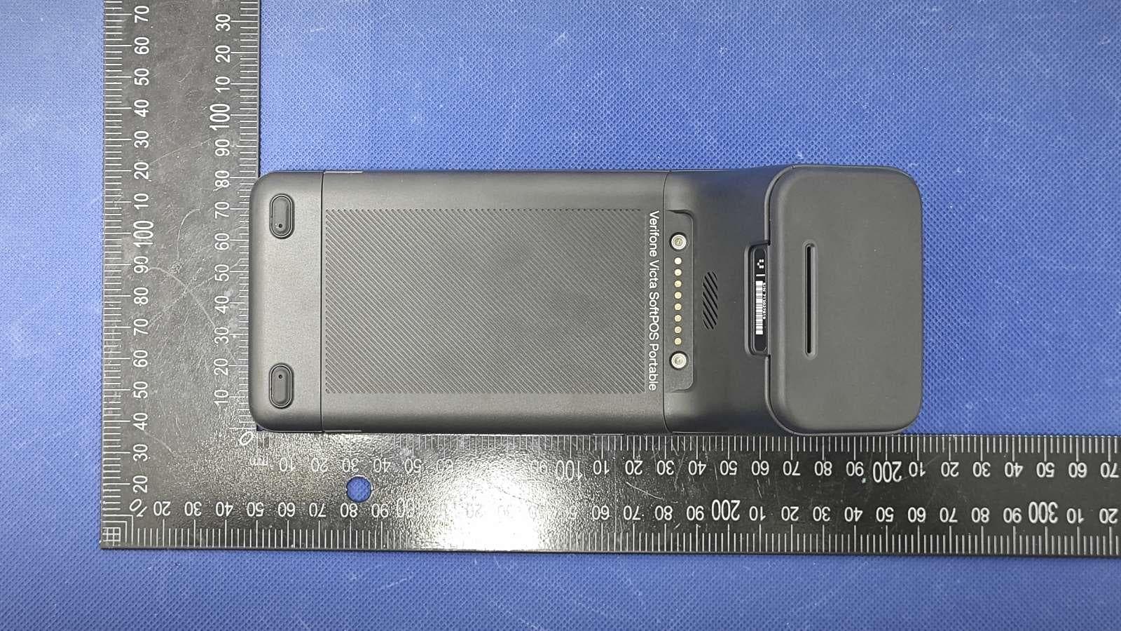
B32VS100P
Jun 22, 2026Point of Sale Terminal
Equipment Class
DXX - Part 15 Low Power Communication Device Transmitter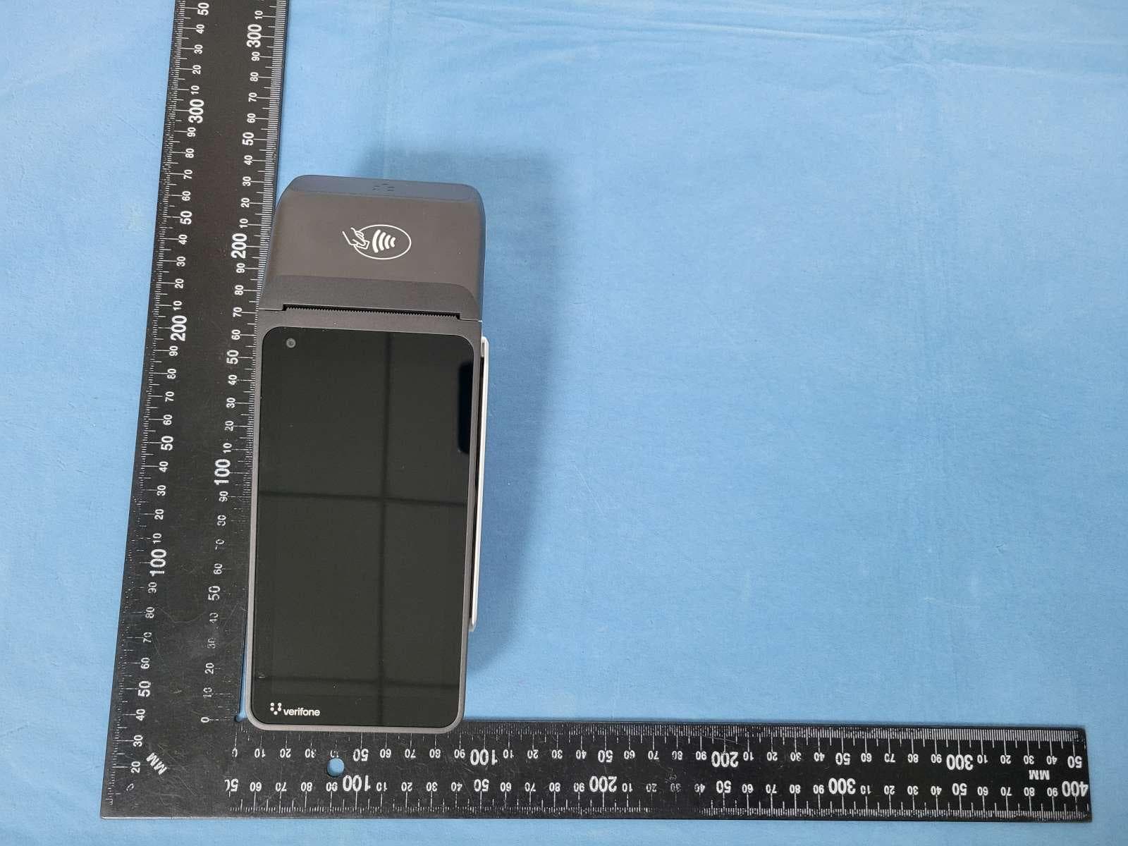
B32V660CA2
Apr 20, 2026Point of Sale Terminal
Equipment Class
NII - Unlicensed National Information Infrastructure TX
B32VM110R
Mar 31, 2026Point of Sale Terminal
Equipment Class
PCB - PCS Licensed Transmitter
B32VN100
Feb 02, 2026Point of Sale Terminal
Equipment Class
DXX - Part 15 Low Power Communication Device Transmitter
B32VS100M
Dec 03, 2025Point of Sale Terminal
Equipment Class
PCE - PCS Licensed Transmitter held to ear