B4S-KR31AKeychain Remote
Authinx Inc.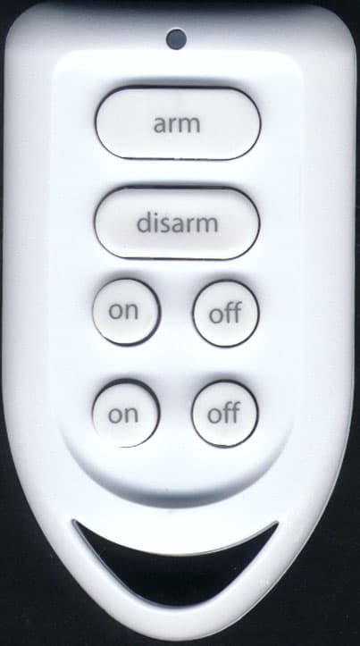
Click to zoom
Application Details
- Equipment Class
- DSC - Part 15 Security/Remote Control Transmitter
- Date of Grant
- Apr 21, 2004
- Application Purpose
- Original Equipment
- Date of Application
- Apr 21, 2004
- Equipment Note
- Keychain Remote
- Frequency Range
- 310.00000000 - 310.00000000
- Company
- Authinx Inc.
- Country
- United States
Documents & Files
Document Text
Text extracted from the exhibit documents filed with the FCC. Open a document above to read the original.
Users Manual
Initializing Keychain RemotesPress and hold the ARM button on the Keychain remote for a secondand then release it. This initializes the remote and picks a randomcode that is used when it is registered with the Console. ENTER PIN12:00 am****12:00 am 1. INSTALLZONE This takes you to the first level of the menu at step 1. This is the INSTALLATIONlevel. The display looks like this:Now simply press any button on the Keychain remote. The Console will acknowl-edge that it has been registered by displaying RMOT 1 SET, RMOT 2 SET, etc. asyou install more remotes.Repeat this for any other Keychain remotes you want to register.Press Clear to back out of the menu. You are asked to confirm, 1. YES, 2 NO.Pressing 1 takes you back to the HOME CONTROL screen. Pressing 2 take you upone level of menu.Registering the Keychain remote with the Console.Press either of the Console’s 2 Menu up/down buttons (to the right of the display).The display then shows ENTER PIN (Personal Identification Number) in the topline. Entering the PIN clears the top line and shows * for each number entered. Thedefault PIN is 0000, you’ll find out later how you can change this, but for now press0000 on the keyboard under the Console’s flip up lid. Arming the systemPress ARM HOME on the Console to arm all Door/Window Sensors instantly. Thisdoes not affect Motion Detectors.Pressing ARM on the Keychain remote always arms in the AWAY mode.Press ARM on the Keychain remote to arm all Door/Window Sensors and MotionDetectors. This arms the system after a set delay. The delay will be what youspecified as the EXIT DELAY (1 minute default). If you arm the system in theAWAY mode you will also have a delay when you enter your home before the alarmtrips, to give you time to disarm it. This delay will be what you specified for yourENTRY DELAY (30 second default).Disarming the systemPressing DISARM on the Keychain remote disarms the system instantly.To disarm from the Console: Press either of the 2 Menu up/down buttons (to theright of the display). The display then shows ENTER PIN (Personal IdentificationNumber) in the top line. ENTER PIN12:00 am****12:00 am DISARMED Entering the PIN clears the top line and shows * for each number entered. Enteryour 4 digit PIN.If the unit is armed, (in either ARMED HOME or ARMED AWAY modes) it willdisarm when the PIN is entered, and return to the time display, with DISARMED inthe top line. Battery ReplacementProviding the batteries have not already failed, they may be replaced with freshbatteries without the need to reinstall the remote. After removing the old batteriesfresh batteries must be fitted within 30 seconds to ensure that the security code isretained.Gently pry the 2 halves of the Keychain remotes case apart and install two CR2016lithium batteries battery in the compartment. Press the 2 halves of the cabinet backtogether.Once the batteries have been replaced, confirm that the remote is still logged in byarming the system. If it does not arm, the code has been lost and you will need toproceed as described below.If the batteries have failed completely, the security code will have been lost. Toensure proper system integrity it is recommended that the Console is cleared and allsensors and remotes reinstalled following the procedures in the Installation chapter. FCC StatementThis equipment generates and uses radio frequency energy, and if not installed andused properly, that is, in strict accordance with the manufacturers instructions, maycause interference to radio and television reception. It has been type tested and foundto comply with the limits for remote control security devices in accordance with thespecifications in Sub-Parts B and C of Part 15 of FCC Rules , which are designed to provide reasonable protection against such interference in a residential installation.However, there is no guarantee that interference will not occur in a particularinstallation. If this equipment does cause interference to radio or television recep-tion, which can be determined by unplugging the equipment, try to correct theinterference by one or more of the following measures.• Reorient the antenna of the radio/TV experiencing the interference.• Relocate the Console with respect to the radio/TV. • Move the Console away from the radio/TV.• Plug the Console into an outlet on a different electrical circuit from the radio/TV experiencing the interference. If necessary, consult your local RadioShack store for additional suggestions. Keychain Remote Cat. No 49-1002 The plug ‘n power Supervised Security System Cat. No 49-1000 includes a SecurityConsole with an automatic dialer that calls neighbors or friends in the event of abreak in. A battery powered RF Door/Window Sensors and battery powered RFMotion Detector to trigger the alarm, and an RF and Keychain Remote control forarming and disarming the system. All sensors and remotes incorporate randomdigital security coding.The system may be configured with any combination of the following items:• Up to 16* Keychain Security Remotes with arm/disarm and panic functions, and buttons to control security lights in and around the home. • Up to 32* magnetic switch operated wireless Door/Window Sensors.• Up to 32* wireless PIR Motion Detectors.• Additional plug ‘n power Home Automation modules such as plug-in lamp and appliance modules and wired-in replacement wall switches can be added to thesystem (one Lamp Module included). This manual for the 49-1000 system describes the installation process for thesecurity elements of the system, and should be referred to as a supplement to thisinstruction booklet.* Note: Door/Window Sensors and Motion Detectors may be added in any combi- nation up to a total of 32. You can also set up 2 wired inputs which will be zones 31and 32. RadioShack Corporation, Ft. Worth, TX 76102.
Block Diagram
KEY MATRIX MCU PIC12C508A 310MHz RFTRANSMITTER BLOCK DIAGRAM FOR KEYFOBModel KR31A (49-1002) 310MHz
ID Label/Location Info
For use with plug 'n power ® Security System, Cat. No. 49-1000. Use two CR2016 lithium batteries. No serviceable parts inside. Remote Control, Cat. No. 49-1002 FCC ID: B4S-KR31A KR31A (49-1002) rating label 2:1 4/13/04 Custom Manufactured in China for RadioShack Corp., Ft. Worth, TX 76102
Operational Description
X-10 Model KR31A Operational Description The model KR31A is a key fob used to activate and deactivate a wireless alarm system. The device transmits when any of the buttons are depressed by the user.When a button is depressed the 310 MHz pulsed RF transmitter inside the KR31A transmits the appropriate pulse code to the alarm receiver to arm and disarm the system.
Parts List/Tune Up Info
KR31A KEYCHAIN REMOTE 20040322 1 098-30080013 LITHIUM BATT. 3V (CR2016) 20040322 2 185000H22850 TOP CABINET 20040322 1 185000H22860 BOTTOM CABINET 20040322 1 275000H12570 RUBBER KEYPAD 20040322 1 851001H12070 PCB ASSY 20040322 1 042010H11277A PCB 20040322 1 076-10900012 CAP-MCC 1P .25P NPO 0603 20040322 1 C8 076-10000012 CAP-MCC 10P .25P NPO 0603 20040322 1 C1 076-10400019 CAP-MCC 100N +8-2 Y5V0603 20040322 1 C7 076-15000023 CAP-MCC 15P 5% NPO 0603 20040322 1 C3 076-80900012 CAP-MCC 8P .25P NPO 0603 20040322 1 C2 080-00000028 SAW RESONATOR 310MHZ 20040322 1 SAW1 124000H10015 RF COIL 18T 20040322 1 L1 210117H10070 TRS-NPN MPS H10 SMD 20040322 1 Q1 211328H10145 IC PIC12C508 SMD 20040322 1 U1 220-00200390 LED-SMD GREEN 2X2.5 20040322 1 LED1 240-68106011 RES-CF 680R +/-5% 1/8W 20040322 1 R4 241-10300003 RES-TFC 10K 5% 1/10W 0603 20040322 1 R3 241-22100003 RES-TFC 220R 5% 1/10W0603 20040322 1 R7 241-27100003 RES-TFC 270R 5% 1/10W 0603 20040322 1 R1 241-68200003 RES-TFC 6K8 5% 1/10W 0603 20040322 1 R2 241-68300003 RES-TFC 68K 5% 1/10W 0603 20040322 1 R5 241-68400003 RES-TFC 680K 5% 1/10W0603 20040322 1 R6 403021H10450A CONTACT PLATE (+VE) 20040322 1 403021H10489 CONTACT PLATE (-VE) 20040322 1
Schematics
1 2 3 4 5 6 78 ABCD 8 7 6 5 4 3 2 1 D CBA Title Number Revision Size A3 Date: 2-Apr-2004 Sheet of File: C:\RS_KFFCC.SCH Drawn By: KEY44/2KEY07/2KEY26/2 KEY 36/3KEY17/3KEY54/3 LED1 R4 680R R2 6K8 R3 10K R1 270R Y1 310MHz Q1 H10 C1 10P C28P C4 * C3 15P PCB TRACE L1 18T +6V BAT1 2 X 2032 DISARM ARM LIGHT1 OFF LIGHT1 ONLIGHT2 ON LIGHT2 OFF Radioshack Keyfob Remote 01 C7 100N +6V 851001H11823 R5 68K R6680K VDD 1 GP5 2 GP4 3 GP3 4 GP2 5 GP1 6 GP0 7 VSS 8 U1 PIC12C508 RFO RFO C81P R4 220R
Test Report
Test Report No. R-10346-3 FCC ID: B4S-KR31A Retlif Testing Laboratories R APPLICANT X-10 USA, Inc. 19823, 58 th Place S. Kent, WA 98032 MANUFACTURER X-10 Electronics Shenzhen Co. Ltd. X-10 Building Labour Industrial District Shenzhen, Xixiang, Bao An Guang Dong, China, 518102 TEST SPECIFICATION: FCC Rules and Regulations Part 15, Subpart C, Para. 15.231 TEST PROCEDURE: ANSI C63.4:2001 TEST SAMPLE DESCRIPTION BRANDNAME: X-10 MODEL: KR31A TYPE: Pulsed Transmitter POWER REQUIREMENTS: 6 VDC via (2) CR2016 Lithium Batteries FREQUENCY OF OPERATION: 310 MHz TESTS PERFORMED Para. 15.231(a), Radiated Emissions, Fundamental and Harmonics Para. 15.231(b), Radiated Emissions, Spurious Case Para. 15.231(b), Duty Cycle Determination Para. 15.231(c), Occupied Bandwidth REPORT OF MEASUREMENTS Applicant: X-10 (USA), Inc. Device: Pulsed Transmitter FCC ID: B4S-KR31A Power Requirements: 6 VDC via (2) CR2016 Lithium Batteries Applicable Rule Section: Part 15, Subpart C, Section 15.231 Test Report No. R-10346-3 FCC ID: B4S-KR31A Retlif Testing Laboratories R REPORT OF MEASUREMENTS (continued) TEST RESULTS 15.231 (a): This device is used as a Remote Control/Security device. 15.231 (a)(1) & The transmitter is manual operated. 15.231 (a)(3): The transmitter does not perform periodic transmissions. 15.231 (b): The fundamental field strength did not exceed 5833 FV/M (Average) at a test distance of 3 meters. In addition, the requirements of section 15.35 for averaging pulsed emissions and for limiting peak emissions were met. The field strength of harmonic and spurious emissions did not exceed 583 FV/M (AVERAGE). DETERMINATION OF FIELD STRENGTH LIMITS The field strength limits shown below are found in Section 15.231. Frequency Limit F1 = 260 3750 = L1 Fo = 310 Lo F2 = 470 12500 = L2 The formula below was utilized to determine the limits: Limit = L1 + [(Fo-F1)(L2-L1)/(F2-F1)] Solving yields: Fundamental Limit = 5833 FV/M (AVERAGE) @ 3 Meters Harmonic Limit = 583 FV/M (AVERAGE) @ 3 Meters Test Report No. R-10346-3 FCC ID: B4S-KR31A Retlif Testing Laboratories R DUTY CYCLE DETERMINATION The unit’s RF output was directly coupled to the input of the spectrum analyzer. The analyzer was set for a frequency span of 0Hz. The sweep time was then adjusted in order to display one full pulse train. The transmitter on time was then summed and compared to the time for one full cycle in order to obtain the duty cycle. (See plots for additional information) Transmitter On Time = 30 milliseconds (maximum) Transmitter Cycle Time = 121.2 milliseconds Transmitter Duty Cycle = 30 % CALCULATION: 1 Large Pulse = 9.0 milliseconds 42 x 500 Fs (small pulse) = 21.0 milliseconds 21+9 = 30 milliseconds Cycle Time = 121.2 milliseconds Duty Cycle (30/100) = 30 % Correction Factor = 20 log(0.30) = -10.4 dB Test Report No. R-10346-3 FCC ID: B4S-KR31A Retlif Testing Laboratories R SPECTRUM ANALYZER DESENSITIZATION CONSIDERATIONS Due to the nature of the emissions being measured, care was taken to ensure that the resolution bandwidth of the spectrum analyzer was adequate to provide accurate measurements. The following formula was utilized: Setting pulse desensitization equal to zero and utilizing the minimum observed pulse width of 500 Fs yields a minimum required bandwidth of 1333 Hz. FCC specified bandwidths of 100 kHz and 1MHz were utilized below and above 1GHz, respectively. GENERAL NOTES 1. All readings were taken utilizing a peak detector function at a test distance of 3 meters. 2. The duty cycle was applied to the peak readings in order to determine the average value of the emissions. 3. The frequency range was scanned from 30 MHz to 3.1 GHz. All emissions not reported were more than 20 dB below the specified limit. Test Report No. R-10346-3 FCC ID: B4S-KR31A Retlif Testing Laboratories R Equipment List FCC 15.231 Transmitter Testing EN Type Manufacturer Description Model No. Cal Date Due 067 Open Area Test Site Retlif 3 Meter RNY 10/1/2003 10/1/2006 128 Double Ridged Guide Electro-Mechanics 1 GHz - 18 GHz 3105 6/13/2003 6/13/2004 133 Broadband Pre-Amplifier Electro-Metrics 10 kHz - 1 GHz, 26dB BPA-1000 6/12/2003 6/12/2004 141 Spectrum Analyzer Hewlett Packard 100 Hz - 40 GHz 8566B 1/26/2004 7/26/2004 141A Graphics Plotter Hewlett Packard N/A 7470A 2/9/2004 2/9/2005 141B Quasi-Peak Adaptor Hewlett Packard 100 Hz - 1 GHz 85650A 1/26/2004 7/26/2004 206B 6.0 dB Attenuator Texscan 0 - 1.0 GHz FP-50 - 6 dB 6/12/2003 6/12/2004 543 Preamplifier Hewlett Packard 1.0 GHz - 26.5 GHz 8449B 7/24/2003 7/24/2004 617 Interference Analyzer Electro-Metrics 10 kHz - 1 GHz EMC-30 9/30/2003 9/30/2004 Test Report No. R-10346-3 FCC ID: B4S-KR31A Retlif Testing Laboratories R FCC 15.231(b) RADIATED EMISSIONS, FUNDAMENTAL & SPURIOUS CASE (See separate e-file named Refundharm.pdf and REspur.pdf) Test Report No. R-10346-3 FCC ID: B4S-KR31A Retlif Testing Laboratories R FCC 15.231(c) OCCUPIED BANDWIDTH (See separate e-file named occbw.pdf) Test Report No. R-10346-3 FCC ID: B4S-KR31A Retlif Testing Laboratories R FCC 15.231(c) DUTY CYCLE (See separate e-file named dutycycle.pdf) Test Report No. R-10346-3 FCC ID: B4S-KR31A Retlif Testing Laboratories R Test Setup Photograph
Contact Information
Applicant
Shane Houshmand(Chief Operating Officer)
Technical Contact
Retlif Testing LaboratoriesThomas J Schneider
[email protected]631-737-1500
795 Marconi Ave. · Ronkonkoma, New York · United States
Non-Technical Contact
Retlif Testing LaboratoriesMichelle White
[email protected]631-737-1500
Test Firm
Retlif Testing LaboratoriesMichael Bozza
Technical Specifications
| # | Rule Parts | Frequency Range | Power Output |
|---|---|---|---|
| 1 | 15.231 | 310 MHz - 310 MHz | - |
Other Applications from Authinx Inc.

B4SXC35A
Jun 16, 2011Wireless Color Camera
Equipment Class
DXX - Part 15 Low Power Communication Device Transmitter
B4SVT50
Jun 16, 2011Wireless Audio/Video System
Equipment Class
DXX - Part 15 Low Power Communication Device Transmitter
B4SVR50
Jun 13, 2011Wireless Audio/Video Receiver
Equipment Class
DSC - Part 15 Security/Remote Control Transmitter
B4S-XC30A
Jun 07, 2011Wireless Color Camera
Equipment Class
DXX - Part 15 Low Power Communication Device Transmitter
B4SIR34A
Aug 01, 2010Remote Control Transmitter
Equipment Class
DSC - Part 15 Security/Remote Control Transmitter