B4SCM15ARemote Control Transmitter
Authinx Inc.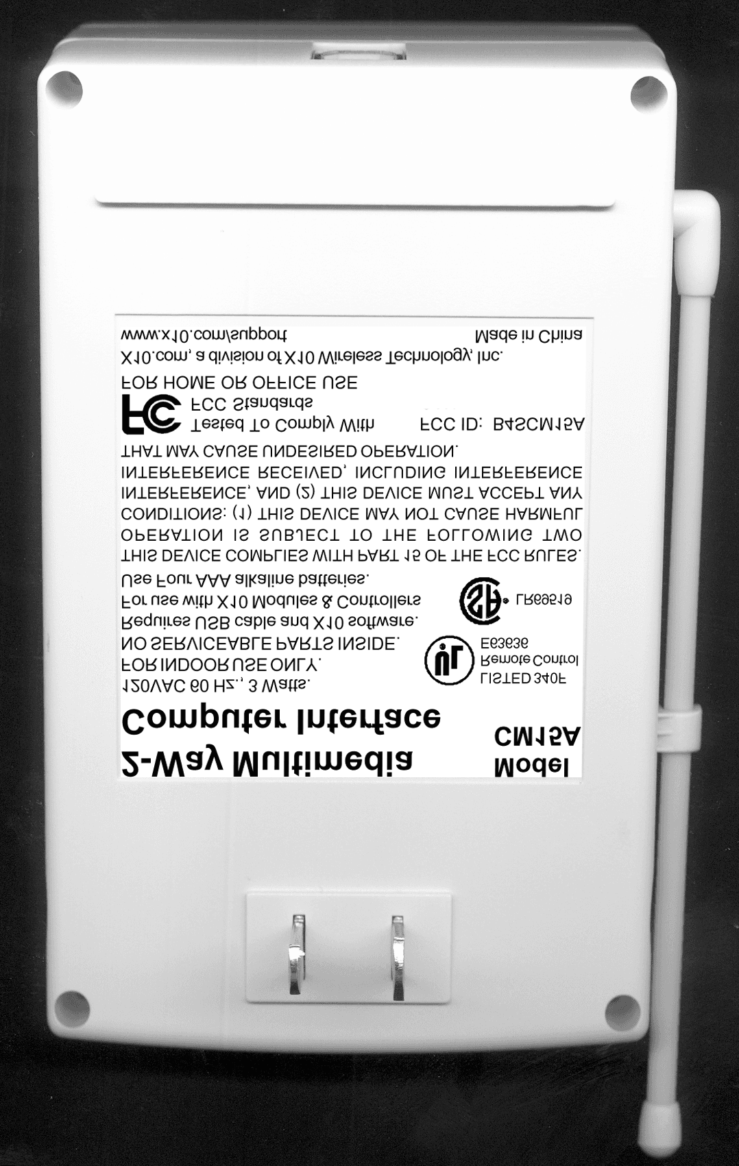
Click to zoom
Application Details
- Equipment Class
- DSC - Part 15 Security/Remote Control Transmitter
- Date of Grant
- Aug 12, 2003
- Application Purpose
- Original Equipment
- Date of Application
- Aug 12, 2003
- Equipment Note
- Remote Control Transmitter
- Frequency Range
- 310.00000000 - 310.00000000
- Company
- Authinx Inc.
- Country
- United States
Documents & Files
Document Text
Text extracted from the exhibit documents filed with the FCC. Open a document above to read the original.
Users Manual
ActiveHome2USB 2-WayHome AutomationInterface Model CM15 A 3 2 Basic Setup1. Download X10 Software. Click on the software link in the e-mail youreceived titled “New SoftwareDownload Link.” Before youdownload the software, choose theoption to save the file, and save it ontoyour desktop so you can more easilyaccess it later. 2. Disable or turn off your anti-virussoftware before you install thesoftware as some anti-virus programsinterfere with the installation.Remember to turn on your anti-virusprogram when you finish these steps. 3. Install Software. Go to your desktopand double click the installationprogram you just downloaded. Thesoftware installation process willinstall the driver for your CM15A. IntroductionThank you for purchasing the X10ActiveHome2 USB Home AutomationInterface. The X10 ActiveHome2 softwareyou purchased, in conjunction with theInterface, lets you control lights andappliances around your home when usedwith X10 Modules.Important: Please download and installthe X10 ActiveHome2 software beforeyou plug in the Interface.The X10 ActiveHome2 software youpurchased should be downloaded from thelink you received in our e-mail titled “NewSoftware Download Link.” This manualassumes that you have already connectedyour lights and appliances to X10 modules,following the instructions that came with themodules. 5 4 4. Plug in the CM15A Interface (wait until the installation program asks youto connect it). 5. Connect the other end of the USB cable to the CM15A Interface.Plug the Interface into an AC outletnear your PC. Using the CM15A InterfaceAll you need to do is run your X10ActiveHome2 software — your softwarecontrols the Interface. Use the entry in yourWindows Start Menu, or double-click theicon on your desktop to open the program.When the program opens click on help forinformation on how to use ActiveHome2. Basic Setup Basic Setup Windows XP Users: When you see a notice that the X10 CM15A ActiveHome2driver has not passed Windows Logo testing,click “Continue Anyway.” Installing thesedrivers will not negatively affect yourcomputer. 7 6 X10 software installation on Windows98 asks for a disk:If your X10 software asks you to insert anX10 disk when you connect the Interface,follow these steps:1. Click OK in this window.2. In the “Insert Disk” window, click the “Browse” button to look for the driverfiles. 3. Go to your C: drive in the browse list and then “Program Files,” “Common Files,”“X10,” “DriverInstall,” and finally“CM15A ActiveHome2.” 4. Click the OK button to use the driver files in that folder. Follow the instructionson your screen after that. If asked for the Windows 98 disk, click“OK.” Insert your Windows 98 CD andbrowse to the “Win98” folder. Click “OK.” TroubleshootingIf you can’t find your link to downloadthe software:You can fill out a form to have the link sentto you again. Go to:http://www.x10.com/supportand click on the link for Secure SoftwareDownload Link, under Technical Support.Enter your e-mail address and order numberto be sent the download link again. Troubleshooting 9 8 Windows 98 or Windows Me says it hasfound an Unknown Device:If you plug in the Interface and get an“Unknown Device” message, you will haveto update the drivers in Windows manually:1. Go to Device Manager by right-clicking on “My Computer” and selecting“Properties.” Then click on the DeviceManager tab. 2. Double click on “Universal Serial Bus Controllers” in the device list, and findthe item called “Unknown Device.” 3. Double-click on it and select the “Driver” tab. Select “Update Driver.” 4. Select “Display a list of all the drivers in a specific location so you can select thedriver you want.” Press the “Next”button. Troubleshooting Troubleshooting 5. Select the “Show all hardware” selection at the bottom of the screen. Choose X10as the manufacturer and then CM15AActiveHome2. Press the “Next” button. 6. Press “Next” to continue. Windows will install the X10 ActiveHome2 driver. 7. At this point your PC should be copying files for the driver. You may need toinsert your Windows CD. When all these steps are done, the driverwill be updated and the screen will sayyou’re finished. 11 10 FCC Caution FCC Caution THIS DEVICE COMPLIES WITH PART15 OF THE FCC RULES. OPERATION ISSUBJECT TO THE FOLLOWING TWOCONDITIONS:(1) THIS DEVICE MAY NOT CAUSEHARMFUL INTERFERENCE, AND(2) THIS DEVICE MUST ACCEPT ANYINTERFERENCE RECEIVED, INCLUD-ING INTERFERENCE THAT MAYCAUSE UNDESIRED OPERATION.This equipment generates and uses radiofrequency energy, and if not installed andused properly, that is, in strict accordancewith the manufacturers instructions, it maycause interference to radio and televisionreception. It has been type tested and foundto comply with the limits for remote controldevices in accordance with the specifica-tions in Sub-Parts B and C of Part 15 ofFCC Rules, which are designed to providereasonable protection against such interfer-ence in a residential installation. However, there is no guarantee that interfer-ence will not occur in a particular installa-tion. If this equipment does cause interfer-ence to radio or television reception, whichcan be determined by unplugging theequipment, try to correct the interference byone or more of the following measures.• Reorient the antenna of the radio/TV experiencing the interference. • Relocate the interface with respect to the radio/TV. • Move the interface away from the radio/ TV. • Plug the interface into an outlet on a different electrical circuit from the radio/TV experiencing the interference. • If necessary, consult your local Dealer for additional suggestions. NOTE: Modifications to any of the compo- nents in this kit will void the user’s authorityto operate this equipment. Warranty X10.com, a division of X10 WirelessTechnology, Inc. (X10) warrants X10 productsto be free from defective material andworkmanship for a period of one (1) year fromthe original date of purchase at retail. X10agrees to repair or replace, at its sole discretion,a defective X10 product …
Text truncated - open the document above for the full version.
Block Diagram
310MHz 310MHz CM15A Block Diagram MCU X10 Transceiver Power Line USB PC 310MHz RF Rx 310MHz RF Tx
ID Label/Location Info
120VAC 60 Hz., 3 Watts. FOR INDOOR USE ONLY. NO SERVICEABLE PARTS INSIDE. Requires USB cable and X10 software. For use with X10 Modules & Controllers Use Four AAA alkaline batteries. Tested To Comply With FCC Standards CM15A USB Computer Interface rating label 2: 1 7/8/03 2-Way Multimedia Computer Interface Model CM15A LISTED 340F Remote Control E63636 LR69519 THIS DEVICE COMPLIES WITH PART 15 OF THE FCC RULES. OPERATION IS SUBJECT TO THE FOLLOWING TWO CONDITIONS: (1) THIS DEVICE MAY NOT CAUSE HARMFUL INTERFERENCE, AND (2) THIS DEVICE MUST ACCEPT ANY INTERFERENCE RECEIVED, INCLUDING INTERFERENCE THAT MAY CAUSE UNDESIRED OPERATION. X10.com, a division of X10 Wireless Technology, Inc. www.x10.com/support Made in China FCC ID: B4SCM15A FOR HOME OR OFFICE USE
Operational Description
CM15A Operational Description The CM15A is a 310 MHz pulsed RF transmitter and USB computer interface. The USB interface provides the remote control commands to be transmitted to a variety of X-10 home automation devices. It is used in conjunction with the X-10 software. The internal MCUs receive information from the USB Interface and convert the data into a pulse code. The pulse code is then sent to the 310 MHz RF transmitter and is used to pulse modulate the 310 MHz carrier.
Parts List/Tune Up Info
0CM15A-101-3UPC INTERFACE (USA) NOPACK1EA 1183010H16240BATTERY DOOR (CM14A)1EA 1183010H16394ANTENNA COVER (WHITE)1EA 1183010H16404ANTENNA HOLDER (WHITE)1EA 1183010H16421PLASTIC TUBE (SNOW WHITE)1EA 1185000H15510TOP CABINET (CM14A)1EA 1185000H15520BOTTOM CABINET (CM14A)1EA 1391-60203010SCREW-PPTT M2.6X12 MS/ZP4EA 1403-02101090MAIN PIN-POLARIZED1EA 1403-02101100MAIN PIN-NON POLARIZED1EA 1403011H10036SPRING CONTACT (C)1EA 1403011H10037SPRING CONTACT (D)2EA 1403011H10115ASPRING CONTACT (+VE)1EA 1403011H10116SPRING CONTACT (-VE)1EA 1851001H11714PCB ASSY, INTERFACE USB1EA 0.2038010H11093PLAIN WHITE LABEL(20X5)MM1EA 0.2042010H10943DPCB1EA 0.2055-10200008CAP-C 1N 10% 50V Y5P1EAC15 0.2055-10300011CAP-C 10N +8-2 50V Y5V1EAC17 0.2055-15200008CAP-C 1N5 10% 50V Y5P2EAC20,28 0.2055-33000003CAP-C 33P 5% 50V NPO3EAC10,21,22 0.2055-47300013CAP-C 47N +8-2 50V Z5U3EAC4,19,24 0.2057-10000029CAP-E 10U 20% 16V1EAC12 0.2057-10100017CAP-E 100U 20% 16V1EAC11 0.2057-10100020CAP-E 100U 20% 35V1EAC1 0.2057-22800006CAP-E 220N 20% 50V1EAC9 0.2057-47100039CAP-E 470U 20% 50V 10X201EAC2 0.2057-47900006CAP-E 4U7 20% 50V 4X71EAC18 0.2058-22400130CAP-MP 220N +/-20% 250V1EAC7 0.2075-10200005CAP-MLC 1N 5% 50V NPO1EAC16 0.2075-15200003CAP-MLC 1N5 5% 50V NPO1EAC14 0.2075-15200008CAP-MLC 1N5 5% 200V NPO1EAC8 0.2084-00300007FUSE WIRE-TN/CU #39 250MA1EAFUSE1 0.2149-00000069USB/A-TYPE SOCKET,SHCU2011EA 0.2159-10100040TUNING COIL H06-424 7.5MM2EATC1,2 0.2159-10100050TUNING COIL H06-351 7.5MM1EATC4 0.2186003H10030INSULATING LABEL1EA 0.2201-15080000TUBE-HS 1.5MM BLACK0.03M 0.2201-40080000TUBE-HS 4MM BLACK0.01M 0.2209-11700640TRS-NPN 2SD667A (100V)1EAQ2 0.2209117H10004TRS-NPN 9014C5EAQ1,3,6,8,10 0.2210117H10000TRS-PNP 9015C3EAQ4,7,9 0.2211103H10017REGULATOR LM2931Z501EAU5 0.2211108H10028IC EEPROM 24C651EAU2 0.2211328H10239IC CY7C637231EAU1 0.2212107H10000DIODE-SI 1N414816EAD1,2,8-19,25,34 0.2212107H10001DIODE-SI 1N40014EAD3-6 0.2212107H10002DIODE-SI 1N40041EAD7 0.2212107H10025DIODE SCHOTTKY IN5818,1A1EAD20 0.2222-10090003DIODE-Z 10V 5% 1W31EAD26 0.2222-68090003DIODE-Z 68V 5% 1W31EAZD3 0.2233-19900020OPTOCOUPLER 4N35 (UL)1EAU4 0.2237-10407032RES-CC 100K +/-10% 1/2W1EAR1 0.2237-15107032RES-CC 150R +/-10% 1/2W1EAR85 0.2240-10106022RES-CF 100R +/-5% 1/4W1EAR32 0.2240-10306022RES-CF 10K +/-5% 1/4W2EAR13,32 0.2240-10406022RES-CF 100K +/-5% 1/4W3EAR7,12,14 0.2240-10506022RES-CF 1M +/-5% 1/4W2EAR4,25 0.2240-12306022RES-CF 12K +/-5% 1/4W3EAR20,21,24 0.2240-12406022RES-CF 120K +/-5% 1/4W1EAR5 0.2240-13206022RES-CF 1K3 +/-5% 1/4W1EAR6 0.2240-15006022RES-CF 15R +/-5% 1/4W1EAR10 0.2240-15106022RES-CF 150R +/-5% 1/4W1EAR18 0.2240-15506022RES-CF 1M5 +/-5% 1/4W2EAR17,30 0.2240-22106022RES-CF 220R +/-5% 1/4W1EAR8 0.2240-22306022RES-CF 22K +/-5% 1/4W1EAR28 0.2240-27306022RES-CF 27K +/-5% 1/4W1EAR9 0.2240-33106022RES-CF 330R +/-5% 1/4W1EAR27 0.2240-33206022RES-CF 3K3 +/-5% 1/4W2EAR2,19 0.2240-39306022RES-CF 39K +/-5% 1/4W1EAR16 0.2240-47206022RES-CF 4K7 +/-5% 1/4W1EAR26 0.2240-47306011RES-CF 47K +/-5% 1/8W1EAR22 0.2240-47406022RES-CF 470K +/-5% 1/4W2EAR3,15 0.2240-82106022RES-CF 820R +/-5% 1/4W1EAR11 0.2240-82306022RES-CF 82K +/-5% 1/4W1EAR23 0.2256-14000015VDR 140VAC, 0.2W, 9X51EAVDR1 0.2307001H10180BTRF-PWR 106/14:29.6 EI281EAP1 0.2354-12200010WIRE UL1015 #22 BLACK0.135MW2 0.2354-12200012WIRE UL1015 #22 RED0.135MW1 0.2354-12600000WIRE UL1007 #26 BLACK0.09MW12 0.2354-12600001WIRE UL1007 #26 BROWN0.09MW10 0.2354-12600002WIRE UL1007 #26 RED0.09MW11 0.2358-60821001WIRE-JUMPER D=0.6MM14EA 0.2852-20202030TRF-ISO 120KHZ,VDE ASSY1EAISO 1851001H11865PCB ASSY (TX, 310MHZ)1EA 0.2042010H11157APCB RF 433M921EA 0.2076-10400014CAP-MCC 100N 10% X7R 06032EAC4,14 0.2076-10900012CAP-MCC 1P .25P NPO 06032EAC3,20 0.2076-12100023CAP-MCC 120P 5% NPO 06031EAC2 0.2076-18900012CAP-MCC 1P8 .25P NPO 06031EAC5 0.2076-22000012CAP-MCC 22P 5% NPO 06032EAC6,15 0.2076-40900012CAP-MCC 4P .25P NPO 06031EAC9 0.2076-47000012CAP-MCC 47P 5% NPO 06031EAC13 0.2076-56000012CAP-MCC 56P 5% NPO 06032EAC8,12 0.2076-90900012CAP-MCC 9P .25P NPO 06032EAC10,11 0.2080-00000028SAW RESONATOR 310MHZ1EASAW1 0.2160-33800001INDUCTOR 330NH 10%1EAL2 0.2160-47700006AINDUCTOR 47N 5% 0805 SMD1EAL1 0.2209-00000003TRS-NPN 2SC3356 SMD2EAQ1,2 0.2241-47200003RES-TFC 4K7 5% 1/10W 06031EAR2 0.2241-68000003RES-TFC 68R 5% 1/10W 06031EAR4 0.2241-68100003RES-TFC 680R 5% 1/10W06032EAR3,6 0.2241-68200003RES-TFC 6K8 5% 1/10W 06032EAR1,5 0.2354-12600008WIRE UL1007 #26 GRAY0.04MANT 1851001H11866PCB ASSY (RX, 310MHZ)1EA 0.2042010H11149APCB1EA 0.2076-10300014CAP-MCC 10N 10% X7R 06031EAC7 0.2076-10500014CAP-MCC 1U +8-2 Y5V 06032EAC4,14 0.2076-12900012*CAP-MCC 12P 5% NPO 06031EACT2 0.2076-18000012CAP-MCC 18P 5% NPO 06031EAC10 0.2076-30900013CAP-MCC 3P .25P N330 06031EACT1 0.2076-33000012CAP-MCC 33P 5% NPO 06032EAC8,9 0.2076-47100014CAP-MCC 470P 5% X7R 06032EAC3,5 0.2076-60900012CAP-MCC 6P .25P NPO 06031EAC1 0.2076-68000012CAP-MCC 68P 5% NPO 06031EAC2 0.2076-82000012CAP-MCC 82P 5% NPO 06031EAC12 0.2159010H10012T-COIL,1.375T,C/W,B/CORE1EAL1 0.2160-10800011INDUCTOR 100NH SMD 06031EAL2 0.2160-68600006INDUCTOR 6N8H 5% 0805 SMD1EAL3 0.2160-82700006INDUCTOR 82NH 5% 0805 SMD1EAL4 0.2211328H10314IC RX3310A SSOP 20L1EAU1 0.2241-10200003RES-TFC 1K 5% 1/10W 06031EAR5 0.2241-10400003RES-TFC 100K 5% 1/10W06032EAR1,6 0.2241-47300003RES-TFC 47K 5% 1/10W 06031EAR7 0.2354-12600008WIRE UL1007 #26 GRAY0.04M ˇ
Schematics
DCBA 12345678 ABCD 8 7 6 5 4 3 2 1 PICO ELECTRONICS Ltd., Eastfield Industrial Estate, Glenrothes, Fife, KY7 4NZ, SCOTLAND SHEET No. DATEDATE REVISION DATE FIRST DRAWN FILEDRNAPPD. DO NOT SCALE DRAWING TITLE: REV. Error : PICO.WMF File Not Found E:\SCH\USBCM14.SCH 11 of B USA Cypress USB Interface PRINT DATE 11:15:01 27-Jun-2003 TC1 KC1047 TR2 2SD667A R1015R ZD3 68V 1.3W R9 27K C8 1n5 200V 5% NP0 R11820R C90.22uF 50V R1310KR12100K R15470K R16 39K C10 33pF TR3 9014C TR4 9015C C141n5 50V 5% NP0 TC3 KC1047 TR6 9014C R18 150R R193K3R2012KC15 1nF TC4 KC1042 R2247KR2112K R2412K R2382K R251M R2822K R301M5 R264K7 R27330R C18 4.7uF16V C170.01uF C1947nF C201n550V C21 33pF C2233pF C447nF C24 47nF C161nF50V 5% NP0 TR7 9015C TR99015C TR89014C D13 D12 D14 D8 D9 D11 FUSE139AWG VDR1V130LA4 C7 0.22UF250VDC D4 D6 D3 D5 R8 220R CONN2LIVE INCONN3 NEUTRAL CONN5 EARTH CONN4 C2 470UF 50V +30V +30V 0V VSS VSS VSS VSS VSS +5V +5V +5V +5V 20/10/00 J4J3 J2J1 IN OUTIN 4 X 1N4001 AGC RESET AGC WINDOW CONTROL X-10 INPUT X-10 O/P GATE D10 4 31 2 6524 3 1 C11100 uF 16V 65 43 61 +6V 4 X 'AAA' D34 VSS CONN6 OUT T1 TBD T2 ISO XFMR R1 100K 0.5W CC D1 TR10 9014 D7IN4004 C1100uF35V R2 3K3 R3 470K R14100K IN OUT COM U5 LM2931Z50 D20 RF IN/OUT DAUGHTER BOARD D25 R85150R0.5 W D2610V 1.3W P1 TAP P2 S2 S1 C12 10uF HMcL R61K3 1234 USB Cable Con R171M5 RedWhiteGreenBlack D16 C28 1500pF 12 54 6 U4 * R3210K A0 1 A1 2 A2 3 VSS 4 SDA 5 SCL 6 WP 7 VCC 8 U2 24C64 D2 D15 D17 D18 D19 P0.0 1 P0.1 2 P0.2 3 P0.3 4 P1.0 5 Vss 6 Vpp 7 Vusb 8 OscIn 9 OscOut 10 Vcc 11 D- 12 D+ 13 P1.1 14 P0.7 15 P0.6 16 P0.5 17 P0.4 18 U1 CY7C63723 +5V 1N5818 TR1 9014 R4 1M R5 120K R7100K 7/11/01 VssRF Out Vcc RF In 1 2 34 ABCD 4 3 2 1 D CBA Title Number Revision Size A4 Date: 26-Jun-2003 Sheet of File: A:\HIMARK5.SCH Drawn By: OSC2 1 FO 2 CPA 3 CPB 4 CPO 5 VSS 6 VSS 7 DATA 8 DISABLE 9 VCC 12 LFB 13 VIRF 14 VEE 15 VORF 16 MIXIN 17 VCC 18 VCC 19 OSC1 20 LIN 11 CPC 10 U1 RX3310A C5470P DISABLE R1 100K VCC C41u C3 470P C2 68P C11 * R2 * C7 10N C1018P C9 33P C8 33P C12 82P L3 6N8 L4 82N R4 * L2 100N R5 1K L1 1.5T C1 6P Ct1 3P Ct2 12P 5V ANT 240MM 310MHz RF RECEIVER (HIMARK) R6 100K R7 47K C14 1U 1 2 34 ABCD 4 3 2 1 D CBA Title Number Revision Size A4 Date: 26-Jun-2003 Sheet of File: A:\310TX-N1.SCH Drawn By: R1 6K8 R2 4K7 R4 22P R3 680R R56K8 SAW1 310MHz PCB2 L1 47N PCB1 C2 120P C1 * C31P C51P8 C6 68R C4 100N Q1 3356 5V C8 56P C7 * C94P C109P C1256P C1347P C11 9P Q2 2SC3356 R6 680R C14100N 5V C1522P RF IN C20 1P 310MHz Tx C21* L2 0.33u 240MM
Test Report
Test Report No. R-9755-1 FCC ID: B4SCM15A APPLICANT X-10 USA, Inc. 19823, 58 th Place S. Kent, WA 98032 MANUFACTURER X-10 Electronics Shenzhen Co. Ltd. X-10 Building Labour Industrial District Shenzhen, Xixiang, Bao An Guang Dong, China, 518102 TEST SPECIFICATION: FCC Rules and Regulations Part 15, Subpart C, Para. 15.231 TEST PROCEDURE: ANSI C63.4:2000 TEST SAMPLE DESCRIPTION BRANDNAME: X-10 USA MODEL: CM15A TYPE: Pulsed Transmitter POWER REQUIREMENTS: 115 VAC, 60 Hz AC Power FREQUENCY OF OPERATION: 310 MHz TESTS PERFORMED Para. 15.207(a), Conducted Emissions Para. 15.231(a), Radiated Emissions, Fundamental and Harmonics Para. 15.231(b), Radiated Emissions, Spurious Case Para. 15.231(b), Duty Cycle Determination Para. 15.231(c), Occupied Bandwidth REPORT OF MEASUREMENTS Applicant: X-10 (USA), Inc. Device: Pulsed Transmitter FCC ID: B4SCM15A Test Report No. R-9755-1 FCC ID: B4SCM15A Power Requirements: 115 VAC, 60 Hz AC Power Applicable Rule Section: Part 15, Subpart C, Section 15.231 Test Report No. R-9755-1 FCC ID: B4SCM15A REPORT OF MEASUREMENTS (continued) TEST RESULTS 15.207(a): The radio frequency voltage that was conducted back on to the AC power line on any frequency/frequencies within the bandwidth of 450 kHz to 30 MHz did not exceed 250 microvolts. 15.231 (a): This device is used as a remote control transmitter. 15.231 (a)(1) & The transmitter is manually operated and ceases transmission within 5 15.231(a)(2): seconds after deactivation. 15.231 (a)(3): The transmitter does not perform periodic transmissions. 15.231 (b): The fundamental field strength did not exceed 5833 μV/M (Average) at a test distance of 3 meters. In addition, the requirements of section 15.35 for averaging pulsed emissions and for limiting peak emissions were met. The field strength of harmonic and spurious emissions did not exceed 583 μV/M (AVERAGE). DETERMINATION OF FIELD STRENGTH LIMITS The field strength limits shown below are found in Section 15.231. Frequency Limit F1 = 260 3750 = L1 Fo = 310 Lo F2 = 470 12500 = L2 Test Report No. R-9755-1 FCC ID: B4SCM15A REPORT OF MEASUREMENTS (continued) The formula below was utilized to determine the limits: Limit = L1 + [(Fo-F1)(L2-L1)/(F2-F1)] Solving yields: Fundamental Limit = 5833 μV/M (AVERAGE) @ 3 Meters Harmonic Limit = 583 μV/M (AVERAGE) @ 3 Meters DUTY CYCLE DETERMINATION The unit’s RF output was directly coupled to the input of the spectrum analyzer. The analyzer was set for a frequency span of 0Hz. The sweep time was then adjusted in order to display one full pulse train. The transmitter on time was then summed and compared to the time for one full cycle in order to obtain the duty cycle. (See plots for additional information) Transmitter On Time = 28.8 milliseconds (maximum) Transmitter Cycle Time = 74 milliseconds Transmitter Duty Cycle = 38.9 % CALCULATION: 1 Large Pulse = 9 milliseconds 33 x 600 μs (small pulse) = 19.8 milliseconds 9 + 19.8 = 28.8 milliseconds Duty Cycle (28.8/74) = 38.9 % Correction Factor = 20 log(0.389) = -8.2 dB Test Report No. R-9755-1 FCC ID: B4SCM15A SPECTRUM ANALYZER DESENSITIZATION CONSIDERATIONS Due to the nature of the emissions being measured, care was taken to ensure that the resolution bandwidth of the spectrum analyzer was adequate to provide accurate measurements. The following formula was utilized: Setting pulse desensitization equal to zero and utilizing the minimum observed pulse width of 600 μs yields a minimum required bandwidth of 1111 Hz. FCC specified bandwidths of 100 kHz and 1MHz were utilized below and above 1GHz, respectively. GENERAL NOTES All readings were taken utilizing a peak detector function at a test distance of 3 meters. The duty cycle was applied to the peak readings in order to determine the average value of the emissions. The frequency range was scanned from 30 MHz to 3.1 GHz. All emissions not reported were more than 20 dB below the specified limit. Test Report No. R-9755-1 FCC ID: B4SCM15A Equipment List FCC Part 15, Paragraph 15.231 Testing EN Type Manufacturer Description Model No. Cal Date Due Date 067 Open Area Test Site Retlif 3 Meter RNY 09/20/2000 09/20/2003 128 Double Ridged Guide Electro-Mechanics 1 GHz - 18 GHz 3105 06/13/2003 06/13/2004 133 Broadband Pre-Amplifier Electro-Metrics 10 kHz - 1 GHz, 26dB BPA-1000 06/12/2003 06/12/2004 141 Spectrum Analyzer Hewlett Packard 100 Hz - 40 GHz 8566B 07/23/2003 01/23/2004 141A Graphics Plotter Hewlett Packard N/A 7470A 03/05/2003 03/05/2004 141B Quasi-Peak Adaptor Hewlett Packard 100 Hz - 1 GHz 85650A 07/23/2003 01/23/2004 206B 6.0 dB Attenuator Texscan 0 - 1.0 GHz FP-50 - 6 dB 06/12/2003 06/12/2004 543 Preamplifier Hewlett Packard 1.0 GHz - 26.5 GHz 8449B 07/24/2003 07/24/2004 767 Biconilog EMCO 26 - 2000 MHz 3142B 09/03/2002 09/03/2003 Test Report No. R-9970-1 FCC ID: B4SCM15A FCC 15.207(a) Conducted Emissions (See separate e-file named cedata.pdf) Test Report No. R-9970-1 FCC ID: B4SCM15A FCC 15.231(b) RADIATED EMISSIONS, FUNDAMENTAL & SPURIOUS CASE (See separate e-file named Refundharm.pdf and REspur.pdf) FCC 15.231(c) OCCUPIED BANDWIDTH (See separate e-file named occbw.pdf) Test Report No. R-9970-1 FCC ID: B4SCM15A FCC 15.231(c) DUTY CYCLE (See separate e-file named dutycycle.pdf) Test Report No. R-9970-1 FCC ID: B4SCM15A Test Setup Photographs
Test Report
Dan, As discussed, the two (2) conducted emissions which did not comply with the average limit with a peak detector were remeasured utilizing a CISPR compliant receiver. The average readings were found to be: 24.00 MHz 48 dBuV (Average) 24.88 MHz 36 dBuV (Average) I trust that this resolves this outstanding issue. Thank you, Richard J. Reitz Laboratory Manager Retlif Testing Laboratories 795 Marconi Avenue Ronkonkoma, NY 11779 (631) 737-1500 x 28 (631) 737-1497 fax www.retlif.com CONFIDENTIALITY : This e-mail and any attachments are confidential and may be privileged. If you are not a named recipient, please notify the sender immediately and do not disclose the contents to another person, use it for any purpose or store or copy the information in any medium.
Test Setup Photos
Test Setup Photographs
Contact Information
Applicant
Shane Houshmand(Chief Operating Officer)
Technical Contact
Retlif Testing LaboritoriesThomas J Schneider
[email protected]631-737-1500
795 Marconi Ave. · Ronkonkoma, New York · United States
Non-Technical Contact
Retlif Testing LaboritoriesMichelle White
[email protected]631-737-1500
Test Firm
Retlif Testing LaboratoriesMichael Bozza
Technical Specifications
| # | Rule Parts | Frequency Range | Power Output |
|---|---|---|---|
| 1 | 15.231 | 310 MHz - 310 MHz | - |
Other Applications from Authinx Inc.

B4SXC35A
Jun 16, 2011Wireless Color Camera
Equipment Class
DXX - Part 15 Low Power Communication Device Transmitter
B4SVT50
Jun 16, 2011Wireless Audio/Video System
Equipment Class
DXX - Part 15 Low Power Communication Device Transmitter
B4SVR50
Jun 13, 2011Wireless Audio/Video Receiver
Equipment Class
DSC - Part 15 Security/Remote Control Transmitter
B4S-XC30A
Jun 07, 2011Wireless Color Camera
Equipment Class
DXX - Part 15 Low Power Communication Device Transmitter
B4SIR34A
Aug 01, 2010Remote Control Transmitter
Equipment Class
DSC - Part 15 Security/Remote Control Transmitter