B4SKR32ASECURITY KEY FOB REMOTE
Authinx Inc.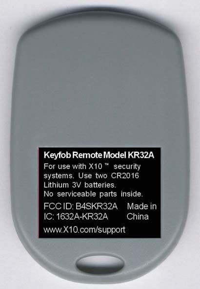
Click to zoom
Application Details
- Equipment Class
- DSC - Part 15 Security/Remote Control Transmitter
- Date of Grant
- Dec 12, 2004
- Application Purpose
- Original Equipment
- Date of Application
- Dec 12, 2004
- Equipment Note
- SECURITY KEY FOB REMOTE
- Frequency Range
- 310.00000000 - 310.00000000
- Company
- Authinx Inc.
- Country
- United States
Documents & Files
Document Text
Text extracted from the exhibit documents filed with the FCC. Open a document above to read the original.
Users Manual
Initializing Keyfob RemotesPress and hold the ARM button on the Keyfob remote for 3-4 secondsand then release it. This initializes the remote and picks a randomcode that is used when it is registered with the Console.The default PIN is 0000, you can change this later, but for now press 0000 on thekeypad (under the lid to the bottom left of the display). This clears the top line andshows * for each number entered.This takes you to the first level of the menu at step 1. This is the INSTALLATIONlevel.Now simply press any button on the Keyfob remote. The Console acknowledges thatit has been registered by beeping and displaying RMOT 1 SET.Repeat this for any other Keyfob Remotes you want to register. The displayincrements to RMOT 2 SET, etc. as you install more remotes.Press Clear to back out of the menu. You are asked to confirm, 1. YES, 2 NO.Pressing 1 takes you back to the HOME CONTROL screen. Pressing 2 takes you upone level of menu.Registering the Keyfob Remote with the ConsolePress either of the Menu up/down buttons (under the lid to the bottom left of thedisplay). The display then shows ENTER PIN (Personal Identification Number) inthe top line. Arming the systemPressing ARM HOME on the Console arms all Door/Window Sensors instantly.Motion Detectors will not trip the system when it is armed in the ARM HOME mode.Pressing ARM AWAY arms with an exit delay and an entry delay, to give you time todisarm the system after you enter your home. These delays will be what you specifiedfor your ENTRY DELAY (30 second default) and EXIT DELAY (1 minute default).Pressing ARM on the Keyfob remote always arms in the AWAY mode. This arms allDoor/Window Sensors AND Motion Detectors, but arms instantly.Disarming the systemPressing DISARM on the Keyfob remote disarms the system instantly.To disarm from the Console: Enter your 4 digit PIN (Personal IdentificationNumber) this will be 0000 unless you changed it.Entering the PIN clears the top line and shows * for each number entered. When you see INSTALL on the display. Press OK and the display looks like this: ENTER PIN12:00 am****12:00 am1. INSTALL1. INSTALLZONE ARMED HOME12:00 am****12:00 amDISARMED12:00 am Panic Alarm: Pressing BOTH Panic buttons at the same time trips the alarm, even if the system was not armed.If the unit is armed it will disarm when the PIN is entered, and return to the timedisplay, with DISARMED in the top line.Then after a short delay the display reverts to HOME CONTROL mode. Battery ReplacementProviding the batteries have not already failed, they can be replaced withfresh batteries without the need to reinstall the remote. After removing theold batteries fresh batteries must be fitted within 30 seconds to ensure thatthe security code is retained.Gently pry the 2 halves of the Keyfob remotes case apart and install twoCR2016 lithium batteries battery in the compartment (+ facing up). Press the2 halves of the cabinet back together.Once the batteries have been replaced, confirm that the remote is still loggedin by arming the system. If it does not arm, the code has been lost and youwill need to proceed as described below.If the batteries have failed completely, the security code will have been lost.You will need to reinstall the Keyfob remote following the instructions insidethis booklet.FCC StatementTHIS DEVICE COMPLIES WITH PART 15 OF THE FCC RULES.OPERATION IS SUBJECT TO THE FOLLOWING TWO CONDITIONS: (1)THIS DEVICE MAY NOT CAUSE HARMFUL INTERFERENCE, AND (2)THIS DEVICE MUST ACCEPT ANY INTERFERENCE RECEIVED,INCLUDING INTERFERENCE THAT MAY CAUSE UNDESIREDOPERATION.NOTE: NO CHANGES OR MODIFICATIONS MAY BE MADE TO THE UNITS. ANY CHANGES MADE TO THE UNITS WILL VOID THEUSER'S AUTHORITY TO OPERATE THE EQUIPMENT.Please visit: http://www.x10.com/support for additional help and warrantyconditions. Security Keyfob RemoteModel KR32A The X10 Supervised Security System Model DS8000 includes a Security Consolewith an automatic dialer that calls friends or relatives in the event of a break in. Abattery powered Radio Frequency (RF) Door/Window Sensors and battery poweredRF Motion Detector to trigger the alarm, and an RF Keyfob Remote Control forarming and disarming the system. All sensors and remotes incorporate random digitalsecurity coding.The system may be configured with any combination of the following items:• Up to 16* Wireless Keyfob Security Remotes with arm/disarm and panic functions, and buttons to control security lights in and around the home. • Up to 30* magnetic switch operated Wireless Door/Window Sensors.• Up to 30* Wireless PIR Motion Detectors.• Optional X10 Home Automation modules such as plug-in lamp and appliance modules and wired-in replacement wall switches can be added to the system. The manual for the DS8000 system describes the full installation process for thesecurity system, and should be referred to as a supplement to this instruction booklet.* Note: Door/Window Sensors and Motion Detectors may be added in any combination up to a total of 30, e.g. 15 Door/Window Sensors and 15 MotionDetectors, or any combination up to a total of 30 . There are also 2 hard wiredinputs, which are zones 31 and 32. X10 Wireless Technology, Inc. Kent WA 98032
Block Diagram
KEY MATRIX MCU PIC12C508A 310MHz RFTRANSMITTER BLOCK DIAGRAM FOR KR32A KEYFOB 310MHz
ID Label/Location Info
For use with X10 ™ security systems. Use two CR2016 Lithium 3V batteries. + facing up. No serviceable parts inside. Keyfob Remote Model KR32A FCC ID: B4SKR32A www.X10.com/support KR32A Keychain Remote rating label 2:1 11/29/04 Made in China
Operational Description
X-10 Model KR32A Operational Description The model KR32A is a key fob used to activate and deactivate a wireless alarm system. The device transmits when any of the buttons are depressed by the user. When a button is depressed the 310 MHz pulsed RF transmitter inside the KR32A transmits the appropriate pulse code to the alarm receiver to arm and disarm the system.
Schematics
1 2 3 4 5 6 78 ABCD 8 7 6 5 4 3 2 1 D CBA Title Number Revision Size A3 Date: 29-Nov-2004 Sheet of File: A:\KR32A-FC.SCH Drawn By: KEY44/2KEY07/2KEY26/2 KEY 36/3KEY17/3KEY54/3 LED1 R4 680R R2 6K8 R3 6K8 R1 270R Y1 310MHz TR1 H10 C1 10P C2 8P C4 * C3 15P PCB TRACE L1 56N +6V BAT1 2 X 2016 ARM DISARM LIGHTS OFF LIGHTS ON PANIC < PANIC > KR32A Keychain Remote 01 C7 100N 8MM L2 +6V R5 68K R6 680K VDD 1 GP5 2 GP4 3 GP3 4 GP2 5 GP1 6 GP0 7 VSS 8 U1 PIC12C508 RFO RFO PCB : 042010H10677CASSY NO. 851001H12196 C8 1P NOTES : ALL UNSPECIFIED CAPACITORS AND RESISTORS ARE USED 0603 TYPE SMD
Test Report
Retlif Testing Laboratories, Test Report R-10683-1, X-10(USA), FCC ID B4SKR32A Page 1 of 16 APPLICANT X-10 USA, Inc. 19823, 58 th Place S. Kent, WA 98032 MANUFACTURER X-10 Electronics Shenzhen Co. Ltd. X-10 Building Labour Industrial District Shenzhen, Xixiang, Bao An Guang Dong, China, 518102 TEST SPECIFICATION: FCC Rules and Regulations Part 15, Subpart C, Para. 15.231 TEST PROCEDURE: ANSI C63.4:2003 TEST SAMPLE DESCRIPTION BRANDNAME: X10 MODEL: KR32A TYPE: Pulsed Transmitter POWER REQUIREMENTS: 6 VDC via (2) CR2016 Lithium Batteries FREQUENCY OF OPERATION: 310 MHz TESTS PERFORMED Para. 15.231(a), Radiated Emissions, Fundamental and Harmonics Para. 15.231(b), Radiated Emissions, Spurious Case Para. 15.231(b), Duty Cycle Determination Para. 15.231(c), Occupied Bandwidth Retlif Testing Laboratories, Test Report R-10683-1, X-10(USA), FCC ID B4SKR32A Page 2 of 16 REPORT OF MEASUREMENTS Applicant: X-10 (USA), Inc. Device: Pulsed Transmitter FCC ID: B4S-DS11A Power Requirements: 6 VDC via (2) CR2016 Lithium Batteries Applicable Rule Section: Part 15, Subpart C, Section 15.231 TEST RESULTS 15.231 (a): This device is used as a remote control transmitter. 15.231 (a)(1) The transmitter is manually operated. Transmission ends within 5 seconds of deactivation. 15.231 (a)(3): The transmitter does not perform periodic transmissions. 15.231 (b): The fundamental field strength did not exceed 5833 μV/M (Average) at a test distance of 3 meters. In addition, the requirements of section 15.35 for averaging pulsed emissions and for limiting peak emissions were met. The field strength of harmonic and spurious emissions did not exceed 583 μV/M (AVERAGE). DETERMINATION OF FIELD STRENGTH LIMITS The field strength limits shown below are found in Section 15.231. Frequency Limit F1 = 260 3750 = L1 Fo = 310 Lo F2 = 470 12500 = L2 The formula below was utilized to determine the limits: Limit = L1 + [(Fo-F1)(L2-L1)/(F2-F1)] Solving yields: Fundamental Limit = 5833 μV/M (AVERAGE) @ 3 Meters Harmonic Limit = 583 μV/M (AVERAGE) @ 3 Meters Retlif Testing Laboratories, Test Report R-10683-1, X-10(USA), FCC ID B4SKR32A Page 3 of 16 DUTY CYCLE DETERMINATION The unit’s RF output was directly coupled to the input of the spectrum analyzer. The analyzer was set for a frequency span of 0Hz. The sweep time was then adjusted in order to display one full pulse train. The transmitter on time was then summed and compared to the time for one full cycle in order to obtain the duty cycle. (See plots for additional information) Transmitter On Time = 30 milliseconds (maximum) Transmitter Cycle Time = 115 milliseconds Transmitter Duty Cycle = 30 % CALCULATION: 1 Large Pulse = 9.0 milliseconds 42 x 500 μs (small pulse) = 21 milliseconds 21+9 = 30 milliseconds Duty Cycle (30/100) = 30 % Correction Factor = 20 log(0.30) = -10.4 dB SPECTRUM ANALYZER DESENSITIZATION CONSIDERATIONS Due to the nature of the emissions being measured, care was taken to ensure that the resolution bandwidth of the spectrum analyzer was adequate to provide accurate measurements. The following formula was utilized: Setting pulse desensitization equal to zero and utilizing the minimum observed pulse width of 500 μs yields a minimum required bandwidth of 1333 Hz. FCC specified bandwidths of 100 kHz and 1MHz were utilized below and above 1GHz, respectively. GENERAL NOTES 1. All readings were taken utilizing a peak detector function at a test distance of 3 meters. 2. The duty cycle was applied to the peak readings in order to determine the average value of the emissions. 3. The frequency range was scanned from 30 MHz to 3.1 GHz. All emissions not reported were more than 20 dB below the specified limit. Retlif Testing Laboratories, Test Report R-10683-1, X-10(USA), FCC ID B4SKR32A Page 4 of 16 EQUIPMENT LIST FCC 15.231 Transmitter Testing EN Type Manufacturer Description Model No. Cal Date Due 067 Open Area Test Site Retlif 3 Meter RNY 10/1/2003 10/1/2006 128 Double Ridged Guide Electro-Mechanics 1 GHz - 18 GHz 3105 6/21/2004 6/21/2005 133 Broadband Pre-Amplifier Electro-Metrics 10 kHz - 1 GHz, 26dB BPA-1000 6/12/2004 6/12/2005 141 Spectrum Analyzer Hewlett Packard 100 Hz - 40 GHz 8566B 8/5/2004 2/5/2005 141A Graphics Plotter Hewlett Packard N/A 7470A 2/9/2004 2/9/2005 141B Quasi-Peak Adaptor Hewlett Packard 100 Hz - 1 GHz 85650A 8/7/2004 2/7/2005 206B 6.0 dB Attenuator Texscan 0 - 1.0 GHz FP-50 - 6 dB 6/12/2004 6/12/2005 543 Preamplifier Hewlett Packard 1.0 GHz - 26.5 GHz 8449B 7/27/2004 7/27/2005 617 Interference Analyzer Electro-Metrics 10 kHz - 1 GHz EMC-30 10/5/2004 10/5/2005 767 Biconilog EMCO 26 - 2000 MHz 3142B 10/7/2004 10/7/2005 Retlif Testing Laboratories, Test Report R-10683-1, X-10(USA), FCC ID B4SKR32A Page 5 of 16 FCC 15.231(b) RADIATED EMISSIONS, FUNDAMENTAL & SPURIOUS CASE Retlif Testing Laboratories, Test Report R-10683-1, X-10(USA), FCC ID B4SKR32A Page 6 of 16 Test Method: FCC Part 15 Subpart C, Spurious Case Radiated Emissions, Paragraph 15.209(a) Customer: X-10 Wireless Technology, Inc Job No. R-10683-1 Test Sample: 310 MHz RF Transmitter Model No.: KR32A FCC ID: B4SKR32A Operating Mode: Continuously Transmitting a pulsed 310 MHz Signal Technician: R. Soodoo Date: December 6, 2004 Notes: Test Distance: 3 Meters Temp: 3°C Humidity: 98% Detector: Quasi-Peak Below 1 GHz, Peak above 1 GHz Test Freq. Antenna Position EUT Orientation Meter Readings Correction Factor Corrected Reading Converted Reading LIMIT MHz (V/H) / Meters Degrees dBuV dB dBuV/m uV/m uV/m 30.00 100 | | | | | | | | | | | | 88.00 100 88.00 150 | | | | | | | NO EMISSIONS OBSERVED AT 3 METERS | | | | | | | | | 216.00 150 216.00 200 | | | | | | 960.00 200 960.00 500 | | | | | | 3100.0 500 The EUT was scanned from 30 MHz to 3.10 GHz The emissions observed from the EUT do not exceed the specified limits. Emissions not recorded were more than 20dB under the specified limit. Retlif Testing Laboratories, Test Report R-10683-1, X-10(USA), FCC ID B4SKR32A Page 7 of 16 Test Method: FCC Part 15 Subpar…
Text truncated - open the document above for the full version.
Test Setup Photos
Retlif Testing Laboratories, Test Report R-10683-1, X-10(USA), FCC ID B4SKR32A Page 1 of 3 X-Axis, Front Y-Axis, Front Retlif Testing Laboratories, Test Report R-10683-1, X-10(USA), FCC ID B4SKR32A Page 2 of 3 Z-Axis, Front X-Axis, Rear Retlif Testing Laboratories, Test Report R-10683-1, X-10(USA), FCC ID B4SKR32A Page 3 of 3 Y-Axis, Rear Z-Axis, Rear
Contact Information
Applicant
Shane Houshmand(Chief Operating Officer)
Test Firm
Retlif Testing LaboratoriesMichael Bozza
Technical Specifications
| # | Rule Parts | Frequency Range | Power Output |
|---|---|---|---|
| 1 | 15.231 | 310 MHz - 310 MHz | - |
Other Applications from Authinx Inc.

B4SXC35A
Jun 16, 2011Wireless Color Camera
Equipment Class
DXX - Part 15 Low Power Communication Device Transmitter
B4SVT50
Jun 16, 2011Wireless Audio/Video System
Equipment Class
DXX - Part 15 Low Power Communication Device Transmitter
B4SVR50
Jun 13, 2011Wireless Audio/Video Receiver
Equipment Class
DSC - Part 15 Security/Remote Control Transmitter
B4S-XC30A
Jun 07, 2011Wireless Color Camera
Equipment Class
DXX - Part 15 Low Power Communication Device Transmitter
B4SIR34A
Aug 01, 2010Remote Control Transmitter
Equipment Class
DSC - Part 15 Security/Remote Control Transmitter