B4SKR34ASLIM FIRE REMOTE MODULE
Authinx Inc.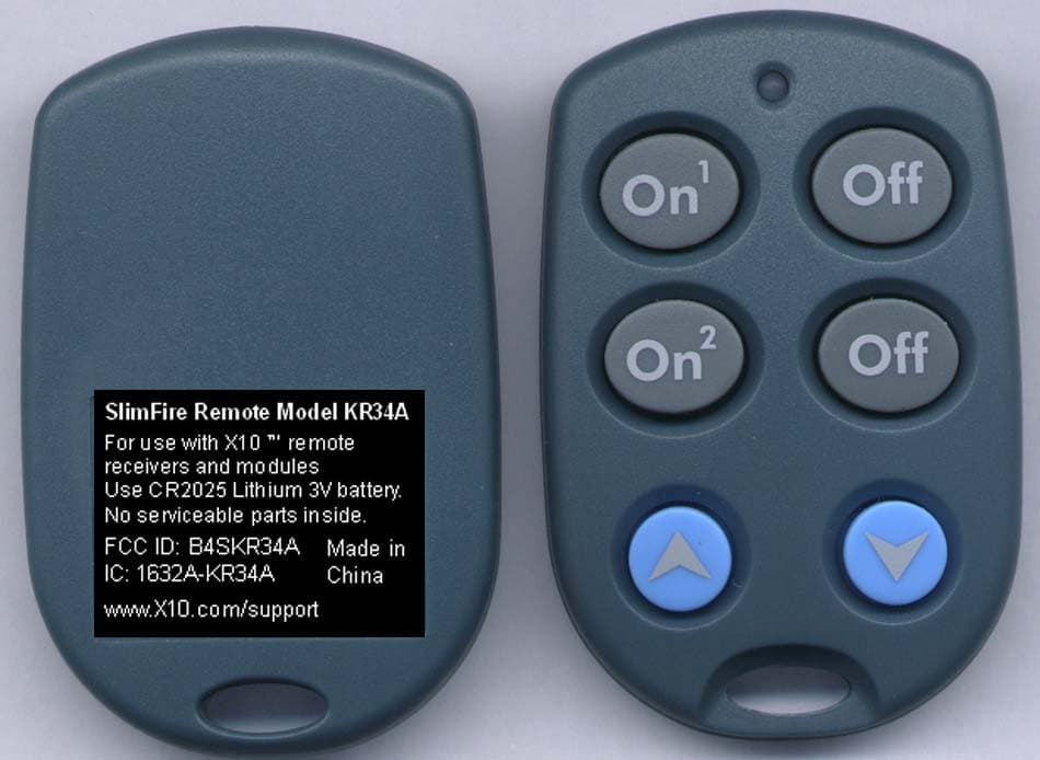
Click to zoom
Application Details
- Equipment Class
- DSC - Part 15 Security/Remote Control Transmitter
- Date of Grant
- Dec 12, 2005
- Application Purpose
- Original Equipment
- Date of Application
- Dec 12, 2005
- Equipment Note
- SLIM FIRE REMOTE MODULE
- Frequency Range
- 310.00000000 - 310.00000000
- Company
- Authinx Inc.
- Country
- United States
Documents & Files
Document Text
Text extracted from the exhibit documents filed with the FCC. Open a document above to read the original.
Users Manual
. X10 Wireless Technology, Inc. LIMITED 1-YEAR WARRANTY X10.com, a division of X10 Wireless Technology, Inc. (X10) warrants X10 products to befree from defective material and workmanship for a period of one (1) year from the originaldate of purchase at retail. X10 agrees to repair or replace, at it’s sole discretion, a defectiveX10 product if returned to X10 within the warranty period and with proof of purchase.If service is required under this warranty:1. Call 1-800-675-3044 or visit www.x10.com, or e-mail [email protected] to obtain a Return Merchandise Authorization (RMA) number. 2. Return the defective unit postage prepaid to X10 (see address on back).3. Enclose a check for $4.00 to cover postage and handling.4. Enclose a dated proof of purchase.5. X10 is not responsible for shipping damage. Units to be returned should be packed carefully. Please visit www.x10.com/warrantyto complete your on-line warranty registration. Thank you.For help or more information on setup, please visit: www.x10.com/support KR34A SlimFire ™ Remote installation and operating instructions The KR34A works with the RR501 (part of the RC5000) and the TM751 (part of the RC6500). It letsyou turn on and off two individually coded X-10 Modules and brighten and dim lights connected to LampModules and Wall Switch Modules. In the default state (after first fitting the battery) the KR34A is setto Housecode A. The first (top) two ON-OFF buttons control modules set to Unit Code 1. The second(middle) two buttons control A2.1. Plug in an X-10 Transceiver (RR501 or TM751, sold separately).2. To turn on or off X-10 Modules set to Unit Code 1 (on Housecode A) press the first (top) ON or OFF button. To turn on or off X-10 Modules set to Unit Code 2 (on Housecode A) press thesecond (bottom) ON or OFF button. To brighten or dim Lamp Modules or Wall Switch Modulespress the number button first, the press Bright or Dim button. If you want to control Modules 1and 2 on Housecode A, that's it. You don't need to read any further. To change the Housecode• Press and hold the first (top) ON button. The red LED blinks once. 3 seconds later, the LED blinks the current setting: 1 blink for Housecode A, 2 blinks for B..... 16 blinks for P. • Release the first (top) ON button. • Press and release the first (top) ON button the appropriate number of times for the Housecode you want to set. Once for A, twice for B, etc. The LED blinks for each press. IMPORTANT:Hold the button on your last press. 3 seconds later, the red LED blinks back the new setting, e.g.3 blinks for Housecode C. I f you do not follow this programming sequence, the LED will stay on for 1 second and your existing setting will not be changed. To change the Unit Code for the first (top) two buttons (the second pair of buttons are always one # higher than the first pair, i.e. if you set the first button to 6, the second button controls 7, etc.). • Press and hold the top OFF button. The red LED blinks once. 3 seconds later, the LED blinks the current setting: 1 blink for Unit Code 1, 2 blinks for 2, 16 blinks for 16. • Release the top OFF button. • Press and release the top OFF button the appropriate number of times for the Unit Code you want. IMPORTANT: Hold the button on your last press. 3 seconds later new code blinks back.I f you do not follow this programming sequence, the LED will stay on for 1 second and your existing setting will not be changed. To change the battery: Pry the unit apart and fit a CR2025 Lithium 3V battery. Observe polarity. F.C.C. CAUTION - THIS DEVICE COMPLIES WITH PART 15 OF THE FCC RULES. OPERATION IS SUBJECT TO THE FOLLOWING TWO CONDITIONS: (1) THIS DEVICE MAY NOT CAUSEHARMFUL INTERFERENCE, AND (2) THIS DEVICE MUST ACCEPT ANY INTERFERENCERECEIVED, INCLUDING INTERFERENCE THAT MAY CAUSE UNDESIRED OPERATION.NOTE: NO CHANGES OR MODIFICATIONS MAY BE MADE TO THE UNITS. ANY CHANGES MADE TO THE UNITS WILL VOID THE USER'S AUTHORITY TO OPERATE THE EQUIPMENT. KR34A-12/05 Press to turnA1 ON. After pressing anumber, press andhold to Brighten. After pressing anumber, press andhold to Dim. Press to turnA2 ON. Press to turnA1 OFF. Press to turnA2 OFF.
Block Diagram
310MHz Transmitter MPU (EM78P153S) 310MHz Block Diagram for KeyChain Remote (KR34A) Key Matrix
ID Label/Location Info
For use with X10 ™ remote receivers and modules Use CR2025 Lithium 3V battery. No serviceable parts inside. SlimFire Remote Model KR34A FCC ID: B4SKR34A IC: 1632A-KR34A www.X10.com/support KR34A Keychain Remote rating label 2:1 12/01/05 Made in China
Operational Description
Model KR34A Operational Description The model KR34AA is a radio frequency transmitter used to activate two individually coded X-10 Modules and brighten and dim lights connected to lamp modules and wall switch modules. The device transmits when the user of the device depresses any of the on or off buttons. When a button is depressed the 310.0 MHz pulsed RF transmitter transmits the appropriate pulse code to the light or wall switch modules to activate them.
Parts List/Tune Up Info
PTNODESQTYREF 851001=12299KR34A PCB ASSY (3V,310MHz) 038010=11093PLAIN WHITE LABEL(20X5)MM1.000 042010=11454APCB1.000 076=10000012CAP-MCC 10P .25P NPO 06031.000C1 076=10400014CAP-MCC 100N 10% X7R 06031.000C7 076=40900012CAP-MCC 4P .25P NPO 06031.000C2 076=50800012CAP-MCC 0P5 .25P NPO 06031.000C8 076=68900012CAP-MCC 6P8 .25P NPO 06031.000C3 080=00000028SAW RESONATOR 310MHz1.000Y1 124000=10015RF COIL 18T1.000L1 209=00000003TRS-NPN 2SC3356 SMD1.000TR1 211328=10324IC EM78P153S OTP-ROM1.000U1 220=00000000LED RED SMD 1.5X31.000LED1 241=00000003RES-TFC 0R 5% 1/10W 06031.000R6 241=22100003RES-TFC 220R 5% 1/10W 06031.000R1 241=33100003RES-TFC 330R 5% 1/10W 06031.000R5 241=68200003RES-TFC 6K8 5% 1/10W 06032.000R2,3 403021=10382CONTACT PLATE (-)1.000 403021=10416ACONTACT PLATE (+VE)1.000
Schematics
1 2 3 4 5 6 78 ABCD 8 7 6 5 4 3 2 1 D CBA Title Number Revision Size A3 Date: 29-Nov-2005 Sheet of File: A:\KR19AFC1.SCH Drawn By: KEY414/10KEY0 14/6 KEY2 14/5 KEY 3 1/5 KEY1 1/6 KEY5 1/10 LED1 R5 330R R2 6K8 R3 6K8 R1 220R Y1 310MHz TR13356 C1 10P C2 4P C3 6P8 PCB TRACE L1 18T 3V BAT1 1 ON 1 OFF 2 OFF 2 ON BRIGHT DIM KEYCHAIN REMOTE 01 C7 100N 3V R6 0R RFO RFO PCB : 042010H11454A ASSY NO. 851001H12299 (3V) C8 0P5 NOTES : ALL UNSPECIFIED CAPACITORS A ND RESISTORS ARE USED 0603 TYPE SMD P50 1 P67 2 P66 3 VDD 4 GND 11 P53 12 P52 13 P51 14 P65 5 P64 6 P63 7 P62 8 P61 9 P60 10 U1 EM78P153S
Test Report
Retlif Testing Laboratories, Test Report R-11238-1, X-10 (USA), Inc., FCC ID: B4SKR34A Page 1 of 19 APPLICANT MANUFACTURER Name: X10 (USA), Inc. Name: X-10 Electronics (Shenzhen) Co. Ltd. Address: 19823 58 th Place South Address: Together Rich Industrial Park B Sanwei Industrial District, Xixiang Town City, State, Zip: Kent, WA 98032 City, State, Zip: Baoan County, Shenzhen, China TEST SPECIFICATION: FCC Rules and Regulations Part 15, Subpart C, Para. 15.231 TEST PROCEDURE: ANSI C63.4:2003 TEST SAMPLE DESCRIPTION BRANDNAME(s): X10 (USA) MODEL(s): KR34A FCC ID: B4SKR34A TYPE: Pulsed Transmitter POWER REQUIREMENTS: 3 VDC derived from CR2025 Lithium Battery FREQUENCY OF OPERATION: 310 MHz APPLICABLE RULE SECTION: Part 15, Subpart C, Section 15.231 TESTS PERFORMED Para. 15.231(a), Radiated Emissions, Fundamental and Harmonics Para. 15.231(b), Radiated Emissions, Spurious Case Para. 15.231(b), Duty Cycle Determination Para. 15.231(c), Occupied Bandwidth Retlif Testing Laboratories, Test Report R-11238-1, X-10 (USA), Inc., FCC ID: B4SKR34A Page 2 of 19 TEST RESULTS 15.231 (a)(1) The transmitter is manually operated. Transmission ends within 5 seconds of deactivation. 15.231 (a)(3): The transmitter does not perform periodic transmissions or the transmitter performs periodic transmissions at predetermined intervals greater than 1 hour apart and are shorter than 1 second in duration. 15.231 (b): The fundamental field strength did not exceed 5833 μV/M (Average) at a test distance of 3 meters. In addition, the requirements of section 15.35 for averaging pulsed emissions and for limiting peak emissions were met. The field strength of harmonic and spurious emissions did not exceed 583.3 μV/M (AVERAGE). 15.231 (c) The Bandwidth of the emission was no wider than 0.25% of the center frequency (775 kHz) as measured 20 db down from the modulated carrier. Retlif Testing Laboratories, Test Report R-11238-1, X-10 (USA), Inc., FCC ID: B4SKR34A Page 3 of 19 DETERMINATION OF FIELD STRENGTH LIMITS The field strength limits shown below are found in Section 15.231: Frequency Limit F1 = 260 3750 = L1 Fo = 310 MHz Lo F2 = 470 12500 = L2 The formula below was utilized to determine the limits: Limit = L1 + [(Fo-F1)(L2-L1)/(F2-F1)] Solving yields Fundamental Limit = 5833 μV/M (AVERAGE) @ 3 Meters Harmonic Limit = 583 μV/M (AVERAGE) @ 3 Meters DUTY CYCLE DETERMINATION The unit’s RF output was directly coupled to the input of the spectrum analyzer. The analyzer was set for a frequency span of 0Hz. The sweep time was then adjusted in order to display one full pulse train. The transmitter on time was then summed and compared to the time for one full cycle in order to obtain the duty cycle. (See plots for additional information). Transmitter On Time =25.1 milliseconds (maximum per cycle) Transmitter Cycle Time = 112 milliseconds (100 ms maximum) Transmitter Duty Cycle =25.1 % CALCULATION 1 Large Pulse =8.6 milliseconds 1 x 8.6 ms (large pulses) =8.6 milliseconds 1 Small Pulse =0.50 milliseconds 33 x 0.50 ms (small pulses) =16.5 milliseconds 8.6 ms + 16.5 ms=25.1 milliseconds Duty Cycle (25.1 / 100) =25.1 % Correction Factor =20 log(0.251)= -12.0 dB Retlif Testing Laboratories, Test Report R-11238-1, X-10 (USA), Inc., FCC ID: B4SKR34A Page 4 of 19 SPECTRUM ANALYZER DESENSITIZATION CONSIDERATIONS Due to the nature of the emissions being measured, care was taken to ensure that the resolution bandwidth of the spectrum analyzer was adequate to provide accurate measurements. The following formula was utilized: Setting pulse desensitization equal to zero and utilizing the minimum observed pulse width of 0.5 milliseconds yields a minimum required bandwidth of1333 Hz. FCC specified bandwidths of 100 kHz and 1 MHz were utilized below and above 1GHz, respectively. GENERAL NOTES 1. All readings were taken utilizing a peak detector function at a test distance of 3 meters. 2. The duty cycle was applied to the peak readings in order to determine the average value of the emissions. 3. The frequency range was scanned from 30 MHz to3.10 GHz. All emissions not reported were more than 20 dB below the specified limit. Retlif Testing Laboratories, Test Report R-11238-1, X-10 (USA), Inc., FCC ID: B4SKR34A Page 5 of 19 Para. 15.231(a), Radiated Emissions, Fundamental and Harmonics Test Data Retlif Testing Laboratories, Test Report R-11238-1, X-10 (USA), Inc., FCC ID: B4SKR34A Page 6 of 19 Test Method: FCC Part 15, Subpart C, Radiated Emissions, Fundamental & Harmonic Emissions. Customer: X-10 (USA) Inc. Job No. R-11238-1 Test Sample: Pulsed 310MHz Transmitter Paragraph: 15.231 Model No.: KR34A FCC ID: B4SKR34A Operating Mode: Continuously Transmitting a pulsed 310 MHz signal. Technician: R. Soodoo Date: December 02, 2005 & December 5, 2005. Notes: Test Distance: 3 Meters Detector: Peak, Unless otherwise specified Test Freq. Antenna Pol./Height EUT Orientation Meter Reading Correction Factor Corrected Reading Converted Reading Peak Limit MHz (V/H)/Meters X / Y / Z dBuV dB dBuV/m uV/m uV/m 310.0 V / 1.0 X 56.8 -12.7 44.1 160.3 58330 | V / 1.5 Y 72.7 -12.7 60.0 1000.0 | | V / 1.5 Z 74.5 -12.7 61.8 1230.3 | | H / 1.0 X 72.4 -12.7 59.7 966.1 | | H / 2.0 Y 67.3 -12.7 54.6 537.0 | 310.0 H / 2.0 Z 66.8 -12.7 54.1 507.0 58330 620.0 V / 1.0 X 42.6 -11.7 30.9 35.1 5833 | V / 2.0 Y 46.6 -11.7 34.9 55.6 | | V / 1.0 Z 46.1 -11.7 34.4 52.5 | | H / 1.0 X 47.3 -11.7 35.6 60.3 | | H / 1.0 Y 42.5 -11.7 30.8 34.7 | 620.0 H / 1.0 Z 37.8 -11.7 26.1 20.2 5833 930.0 V / 1.0 X 29.6 -9.5 20.1 10.1 5833 | V / 1.0 Y 34.2 -9.5 24.7 17.2 | | V / 1.0 Z 36.8 -9.5 27.3 23.2 | | H / 1.0 X 31.3 -9.5 21.8 12.3 | | H / 2.0 Y 28.5 -9.5 19.0 8.9 | 930.0 H / 2.0 Z 27.4 -9.5 17.9 7.9 5833 1240.0 V / 1.0 X 42.4 -15.2 27.2 *22.9 5000 | V / 1.0 Y 42.4 -15.2 27.2 *22.9 | | V / 1.0 Z 42.4 -15.2 27.2 *22.9 | | H / 1.0 X 40.1 -15.2 24.9 *17.6 | | H / 1.0 Y 40.1 -15.2 24.9 *17.6 | 1240.0 H / 1.0 Z 40.1 -15.2 24.9 *17.6 5000 1550.0 V / 1.0 X 42.2 -15.2 27.0 *22.4 5000 | V / 1.0 Y 42.2 -15.2 27.0 …
Text truncated - open the document above for the full version.
Test Setup Photos
Radiated Emissions Test Setup (X-axis) Radiated Emissions Test Setup (Y-axis) Radiated Emissions Test Setup (Z-axis)
Contact Information
Applicant
Shane Houshmand(Chief Operating Officer)
Test Firm
Retlif Testing LaboratoriesMichael Bozza
Technical Specifications
| # | Rule Parts | Frequency Range | Power Output |
|---|---|---|---|
| 1 | 15.231 | 310 MHz - 310 MHz | - |
Other Applications from Authinx Inc.

B4SXC35A
Jun 16, 2011Wireless Color Camera
Equipment Class
DXX - Part 15 Low Power Communication Device Transmitter
B4SVT50
Jun 16, 2011Wireless Audio/Video System
Equipment Class
DXX - Part 15 Low Power Communication Device Transmitter
B4SVR50
Jun 13, 2011Wireless Audio/Video Receiver
Equipment Class
DSC - Part 15 Security/Remote Control Transmitter
B4S-XC30A
Jun 07, 2011Wireless Color Camera
Equipment Class
DXX - Part 15 Low Power Communication Device Transmitter
B4SIR34A
Aug 01, 2010Remote Control Transmitter
Equipment Class
DSC - Part 15 Security/Remote Control Transmitter