B4SPM725T[email protected]
Authinx Inc.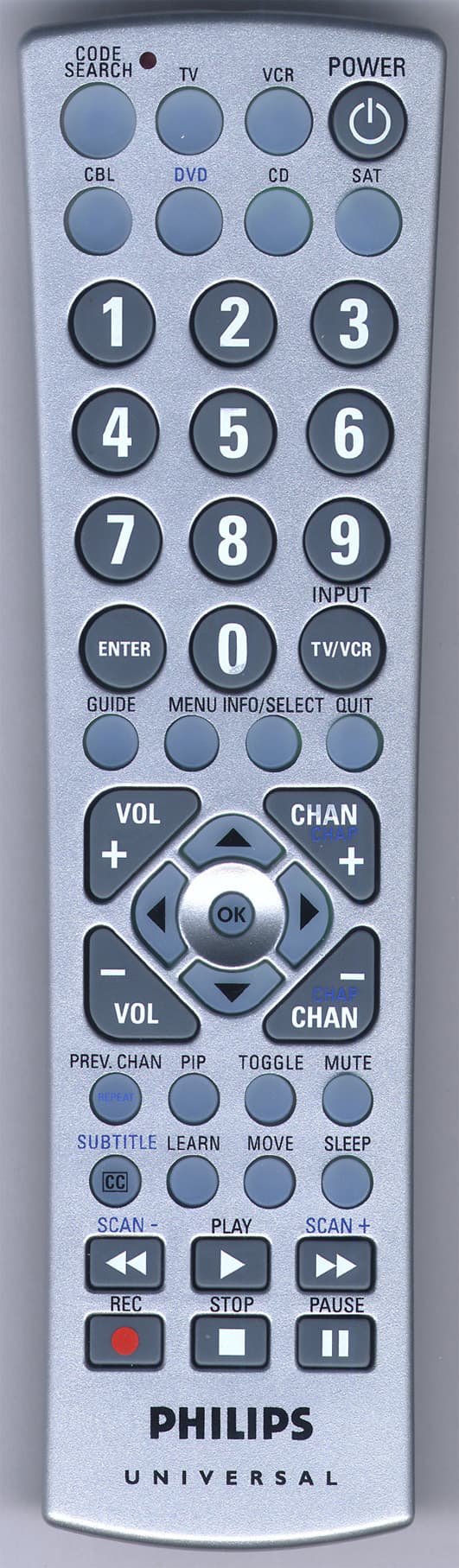
Click to zoom
Application Details
- Equipment Class
- DSC - Part 15 Security/Remote Control Transmitter
- Date of Grant
- May 14, 2006
- Application Purpose
- Original Equipment
- Date of Application
- May 14, 2006
- Equipment Note
- [email protected]
- Frequency Range
- 418.00000000 - 418.00000000
- Company
- Authinx Inc.
- Country
- United States
Documents & Files
Document Text
Text extracted from the exhibit documents filed with the FCC. Open a document above to read the original.
Users Manual
Universal Remote Model PM725T 32 IntroductionTable of Contents Introduction...................................................... 3 Button Functions............................................... 4 SAT/DVD Functions.................................... 6 Setup............................................................... 7 Battery Installation....................................... 7 Battery Saver............................................... 7 Code Saver ................................................. 7 Power-On default........................................ 7 Code Setup ................................................. 7 Code Entry....................................................... 8 Direct Code Entry........................................ 8 Code Search ............................................... 8 Brand Search............................................... 9 Code Identification Feature............................. 10 Sleep Timer.................................................... 10 Programming Combo Device Codes............... 11 Controlling Combo Devices............................ 11 Controlling Devices with Power On and Off.... 11 VCR/DVD/DVR Punch-Through Feature....... 12 Volume/Mute Control Feature......................... 12 Setting Volume/Mute Control, Punch-Through . 13 Setting any Mode to use its own Volume/Mute 13 Code Learning................................................ 14 Tips on Learning........................................ 14 IR Transmitter Finder Feature..................... 16 Learning Commands....................................... 17 Clearing Commands....................................... 18 Clearing Learned commands for a mode..... 18 Master Clear............................................. 18 TV/VCR/INPUT............................................ 18 IR Extender Feature....................................... 19 Troubleshooting.............................................. 20 Congratulations on your purchase of a Philips Universal Remote Control. Philips Universal Remotes let you replace a broken or lost remote or combine more than one remote into one. In addition, this remote is equipped with a command learning feature which lets the remote learn commands from your original equipment remote control! This remote control operates the common features of most but not all models and brands of IR Infrared Controlled Video Equipment. This remote may provide functions that are not available on your equipment. Some functions of your particular equipment (e.g. menu functions) may not be controlled by this remote. In such cases, use the original remote control for your equipment. Please use this manual to become familiar with your Philips Universal Remote. After you are familiar with your remote the first thing you need to do is to install batteries and setup your remote for your particular product and brand. The remote also transmits wireless Radio Fre- quency (RF) commands to the video sender. The video sender receives these commands and converts them to regular Infrared (IR) commands. These IR commands are then emitted from an IR Extender cable to control your A/V components. This lets you control your A/V components from ANY room in your home - you don’t need to aim the remote at your component! Thank you for buying a Philips remote and we hope it will give you many years of service. 54 Button Functions, cont. Button Functions Note: The REC button must be pressed TWICE to record from your VCR. For some brands of VCRs, you might need to press the REC button once, then press it again for three seconds. Some buttons on the remote might have functions that are referred to by different names on the device you are controlling. E.G. PREV.CHAN may be called RECALL, or ENTER may be called DISPLAY. These differences depend on the brand and model of your product. Also, this remote can only operate features that exist on your product. E.G., your product must have PREV.CHAN ability for the PREV.CHAN button to operate this feature. 1. TV, VCR, DVD,CBL, AUX, CD, SAT Selects product to be operated. 2. NUMBERS Enter numbers for direct channel selection. Some products require Enter to be pressed after channel selection. 3. ENTER Used after direct channel number entry to immediately change to the selected channel. 4. MENU brings up the DVD disc Menu screen - use with the UP, DOWN, LEFT & RIGHT navigation buttons. 5. GUIDE brings up the DVD Title Menu screen. Displays on-screen program guide. 6. VOLUME UP/DOWN Changes the volume level of the product, normally the TV. 7. UP, DOWN, LEFT & RIGHT navigation buttons. 8. OK Selects menu items for the device you are controlling. 9. PREV. CHAN Returns to the previously selected channel, or DVD repeat toggle. REPEAT A-B performs DVD players “A-B Repeat” (or RPT A.B) function for repeat play of current Chapter or Track. 10. PIP TV Picture-in- Picture control. 11. CC (SUBTITLE) TV Closed Caption (if your TV has this feature) or DVD Subtitle toggle. 12. LEARN Used to setup learning functions. 13. RECORD, PLAY, STOP, REW, FF, PAUSE VCR control buttons operate your VCR even when the remote is set to operate the TV. Also operates DVD Scan -/+. 14. CODE SEARCH Used for setup. 15. SLEEP Turns off the TV after a period of 1 to 99 minutes. 16. MUTE Turns off the TV sound while the picture remains. 17. TOGGLE Swaps TV PIP screens. 18. CHANNEL UP/DOWN Changes the channels. CHAPTER +/- controls DVD/CD track selection i.e. DVD/CD Track Skip Up/Down (in DVD and SAT modes). Note the VCR buttons also control DVD when in DVD Mode. 19. QUIT Used to exit menu functions. 20. INFO/SELECT Displays/selects on-screen channel information, etc. 21. TV/VCR/INPUT For some TVs, press repeatedly to select from available viewing sources (antenna, cable box, VCR, etc.). 22. POWER Turns product On or Off. 23. Red Indicator Lights when any button is pressed. 1. 2. 3. 4. 5. 6. 7. 8. 9. 10. 11. 12. 23. 22. 21. 20. 19. 18. 17. 16. 15. 14. 13. 76 Setup Battery Ins…
Text truncated - open the document above for the full version.
Block Diagram
IR Driver EEPROM 128K MCU Block Diagram for RF Remote (PM725T) Key Matrix 418MHz RF Transmitter 418MHz
ID Label/Location Info
6 in 1 RF Universal Remote Use with R215 Video Receiver. Use two AAA alkaline batteries. 1. Press and hold CODE SEARCH until red light stays on. 2. Press and release mode button (TV, VCR, CBL, etc. 3. Enter 3 digit code from code list. FCC ID: B4SPM725T PM725T remote rating label 2: 1 5/9/06 Model PM725T Philips North America, Ledgewood, NJ 07852 Made in China IC: 1632A-PM725T
Operational Description
Model PM725T Operational Description The model PM725T is a radio frequency transmitter utilized to transmit radio frequency commands to a video sender. The device transmits when the user of the remote depresses any of the buttons. When a button is depressed, the 418 MHz pulsed RF transmitter transmits the appropriate pulse code to the video sender.
Parts List/Tune Up Info
2006/04/5/2006 14:03 SYSTEM X10 BILL O F MATERIALPAGE 1 LEVEL PART IDENTIFIE RDESCRIPTIONEFF DATEQTY/ASSYREFERENCE -------------------------------------------------------------------------------------- 0 PM725T (A)=77U 7IN1 SILVER IR/RF REMOTE200605041 1 038010=11093PLAIN WHITE LABEL (20X5)MM200605042 1 183010=22590BATTERY DOOR200605041 1 185000=20810ABOTTOM CABINET200605041 1 185000=25012TOP CABINET,SILVER200605041 1 275000=13413RUBBER KEYPAD200605041 1 851001=11204REMOTE RF 418MHZ W/ 3V200605041 0.2 042010=10437DPCB RF 433M92/418M200006261 0.2 076=10900000CAP-MCC 1P .25P NPO 0805200006261 C4 0.2 076=22000002CAP-MCC 22P 5% NPO 0805200006261 C3 0.2 076=68900000CAP-MCC 6P8 .25P NPO 0805200006262 C1,5 0.2 080001=10021SAW 418MHZ SIEMENS200006261 SAW 0.2 124000=10015RF COIL 18T200006261 L3 0.2 162089=10014RF WIRE LOOP ID=6 WD=0.6200006261 L2 0.2 162089=10025COIL 2T5R ID=2 WD=0.4200006261 R4 0.2 210117=10070TRS-NPN MPS H10 SMD200006261 TR1 0.2 241=10300000RES-TFC 10K 5% 1/10W 0805200006262 R1,3 0.2 241=27100000RES-TFC 270R 5% 1/10W 0805 200006261 R2 0.2 354=12400000WIRE UL1007 #24 BLACK200108230.133 0.2 358=60821001WIRE-JUMPER D=0.6MM200006263 1 851001=12443PCB ASSY,MX006200605041 0.2 057=10100053CAP-E 100U 20% 10V200512061 C2 0.2 057=10900011CAP-E 1U 20% 50V 3X5200512061 C5 0.2 076=10400014CAP-MCC 100N 10% X7R 0603 200512062 C3,6 0.2 080001=100504MHZ RESONATOR W/2 CAP200512061 Y1 0.2 209=00000001TRS-NPN 2N3904 SMD200512061 Q11 0.2 209=00000016TRS-NPN 9013 (SOT-23)200512061Q1 0.2 209=00000017TRS-NPN 9014D (SOT-23)200512062Q2,4 0.2 211108=10031IC EEPROM 24C16 SMD200512061 U2 0.2 220=00200220IR EMITTING LED 5MM200512061 IR1 0.2 220=00200350LED 2MM-TOWER RED200512061 LED1 0.2 241=10100003RES-TFC 100R 5% 1/10W0603200512061 R8 0.2 241=10200003RES-TFC 1K 5% 1/10W 0603200512061 R14 0.2 241=10300003RES-TFC 10K 5% 1/10W 0603200512061 R17 0.2 241=10500003RES-TFC 1M 5% 1/10W 0603200512061 R1 0.2 241=33100003RES-TFC 330R 5% 1/10W0603200512061 R4 0.2 241=33900003RES-TFC 3R3 5% 1/10W 0603200604051 R3 0.2 241=47100003RES-TFC 470R 5% 1/10W0603200603271 R2 0.2 241=47300003RES-TFC 47K 5% 1/10W 0603200512061 R9 0.2 241=47400003RES-TFC 470K 5%1/10W 0603200512061 R10 0.2 241=82200003RES-TFC 8K2 5% 1/10W 0603200512061 R7 0.2 403011=10362SPRING CONTACT (+VE)200512061 0.2 403011=10363SPRING CONTACT (-VE)200512061 0.2 851001=12443-A PCB ASSY,DIE,MX006200512061 ..3042010=11568BPCB200512061 ..3211328=10370-D IC DIE MX006200512061 •
Schematics
1 2 34 ABCD 4 3 2 1 D CBA Title Number Revision Size A4 Date: 10-Dec-2004 Sheet of File: A:\RF418-TX.SCH Drawn By: TR1 H10 R1 10K R3 10K R2 270R C5 6P8 C322PC1 5P6 L2 6MM L3 18T L1 3.5T SAW1 418MHz RF INPUT +3V C4 1P RF 418MHz Tx 90MM ANT PCB TRACE DCBA 12345678 ABCD 8 7 6 5 4 3 2 1 PICO ELECTRONICS Ltd., Eastfield Industrial Estate, Glenrothes, Fife, KY7 4NZ, SCOTLAND SHEET No. DATEDATE REVISION DATE FIRST DRAWN FILEDRNAPPD. DO NOT SCALE DRAWING TITLE: REV. Error : PICO.WMF File Not Found C:\DOCUME~1\ADMINI~1\ \PM725SMA.SCH 桌面 11 of A PM72 5T RF REMOTE PRINT DATE 10:34:45 6-Dec-2005 BKW 28/11/05 28/11/05 28/11/05 LED1 R2 470R C3100NF VSS C2220UF6.3V Y14MHZ R11M NOTES:-1/ ALL UNSPECIFIED DIODES 1N4148 OR EQUIVALENT.2/ ALL UNSPECIFIED CAPACITORS ARE SMD TYPE.3/ ALL UNSPECIFIED RESISTORS ARE SMD TYPE."*" DENOTES COMPONENT NOT INSTALLED +3V VSS KEY34 MENU 10/21KEY50 7 10/23 KEY43 DOWN 11/22 KEY53 ENTER 13/23 KEY54 8 14/23 KEY36 QUIT 12/21 KEY31 TOGGLE 15/20KEY47 UP 15/22KEY55 0 15/23 KEY56 SAT 16/23KEY40 AUX 16/21KEY8 CD 16/17KEY48 CBL 16/22 KEY4 FF 12/17 KEY5 PAUSE 13/17 KEY46 OKAY 14/22 KEY2 REWIND 10/17 KEY3 RECORD 11/17 KEY42 LEFT 10/22 KEY44 RIGHT 12/22 KEY45 GUIDE 13/22 KEY52 9 12/23 KEY6 PLAY 14/17 KEY7 STOP 15/17 KEY30 PIP 14/20 KEY51 INPUT 11/23 (TV/VCR) KEY58 1 10/24 KEY61 6 13/24 KEY62 2 14/24 KEY63 5 15/24 KEY64 DVD 16/24 KEY60 3 12/24 KEY59 4 11/24 KEY66 VOL.DOWN 10/25 KEY69 CH UP 13/25 KEY70 MUTE 14/25 KEY71 POWER 15/25 KEY72 VCR 16/25 KEY68 VOL.UP 12/25 KEY67 CH.DOWN 11/25 KEY74 CODESEARCH 10/26 KEY77 PREV.CHAN 13/26 KEY78 SLEEP 14/26 KEY79 INFO 15/26 (Display) KEY80 TV 16/26 KEY76 CC 12/26 KEY75 LEARN 11/26 P1-5 30 P1-4 29 P1-2 27 SPK1 34 SPK2 36 TEST 6 /RES 5 X32I 8 X32O 7 P0-7 16 P0-6 15 P0-5 14 P0-4 13 P0-3 12 P0-2 11 P2-1 18 P2-0 17 P2-3 20 P2-2 19 P2-5 22 P2-4 21 P2-7 24 P2-6 23 P1-1 26 P1-0 25 P0-0 9 P1-6 31 AVDD 35 P1-7 32 OSCI 3 OSCO 2 AGND 33 P0-1 10 P1-3 (IRO) 28 VDD 1 GND 4 U1 USA-MX006 IR1 TR1 9013G VSS R4330R VSS 2 x AAA BATTERIES BATT1BATT2 A0 1 A1 2 A2 3 VSS 4 SDA 5 SCL 6 WP 7 VCC 8 U224LC16B VDD VSS TO LEARN CCT. LEARN GATE TO LEARN INPUT CLOCKDATA TR49014D R947K R10470K R141K VDD GATE FROM LED PORT 1:7 IR INPUT SIGNAL C51UF10V R1710K TR2 9014D +3V R8 100R TR119014 R78K2 C6100NF +3V VSS
Test Report
Retlif Testing Laboratories, Test Report R-11452-1, X10 (USA), Inc., FCC ID: BS4PM725T Page 1 of 21 TECHNICAL INFORMATION APPLICANT MANUFACTURER Name: X10 (USA), Inc. Name: X-10 Electronics (Shenzhen) Co. Ltd. Address: 19823 58 th Place South Address: Together Rich Industrial Park B Sanwei Industrial District, Xixiang Town City, State, Zip: Kent, WA 98032 City, State, Zip: Baoan County, Shenzhen, China TEST SPECIFICATION: FCC Rules and Regulations Part 15, Subpart C, Para. 15.231 TEST PROCEDURE: ANSI C63.4:2003 TEST SAMPLE DESCRIPTION BRANDNAME(s): X10 (USA) MODEL(s): PM725T FCC ID: BS4PM725T TYPE: Pulsed Transmitter POWER REQUIREMENTS: 3 VDC derived from two (2) AAA Batteries. FREQUENCY OF OPERATION: 418 MHz APPLICABLE RULE SECTION: Part 15, Subpart C, Section 15.231 TESTS PERFORMED Para. 15.231(a), Radiated Emissions, Fundamental and Harmonics Para. 15.231(b), Radiated Emissions, Spurious Case Para. 15.231(b), Duty Cycle Determination Para. 15.231(c), Occupied Bandwidth Retlif Testing Laboratories, Test Report R-11452-1, X10 (USA), Inc., FCC ID: BS4PM725T Page 2 of 21 TEST RESULTS 15.231 (a): This device transmits a control signal and is used as a remote control transmitter. 15.231 (a)(1) The transmitter is manually operated. Transmission ends within 5 seconds of deactivation. 15.231 (a)(3): The transmitter does not perform periodic transmissions or the transmitter performs periodic transmissions at predetermined intervals greater than 1 hour apart and are shorter than 1 second in duration. 15.231 (b): The fundamental field strength did not exceed 10333.3 μV/M (Average) at a test distance of 3 meters. In addition, the requirements of section 15.35 for averaging pulsed emissions and for limiting peak emissions were met. The field strength of harmonic and spurious emissions did not exceed 1033.3 μV/M (AVERAGE). 15.231 (c) The Bandwidth of the emission was no wider than 0.25% of the center frequency (63.8 kHz) as measured 20 db down from the modulated carrier. Retlif Testing Laboratories, Test Report R-11452-1, X10 (USA), Inc., FCC ID: BS4PM725T Page 3 of 21 DETERMINATION OF FIELD STRENGTH LIMITS The field strength limits shown below are found in Section 15.231: Frequency Limit F1 = 260 3750 = L1 Fo = 418MHz Lo F2 = 470 12500 = L2 The formula below was utilized to determine the limits: Limit = L1 + [(Fo-F1)(L2-L1)/(F2-F1)] Solving Yields Fundamental Limit = 10333.3 μV/M (AVERAGE) @ 3 Meters Harmonic Limit = 1033.3 μV/M (AVERAGE) @ 3 Meters DUTY CYCLE DETERMINATION The unit’s RF output was directly coupled to the input of the spectrum analyzer. The analyzer was set for a frequency span of 0 Hz. The sweep time was then adjusted in order to display one full pulse train. The transmitter on time was then summed and compared to the time for one full cycle in order to obtain the duty cycle. (See plots for additional information). Transmitter On Time = 25.76 milliseconds (maximum per cycle) Transmitter Cycle Time = 100.8 milliseconds (100 ms maximum) Transmitter Duty Cycle =26 % CALCULATION 1 Large Pulse =8.6 milliseconds 33 x 520 μs (small pulse) = 17.16 milliseconds 8.6 + 17.16= 25.76 milliseconds Duty Cycle (25.76/100)*100 =26.0 % Correction Factor =20 log (0.26)= -11.7 dB Retlif Testing Laboratories, Test Report R-11452-1, X10 (USA), Inc., FCC ID: BS4PM725T Page 4 of 21 SPECTRUM ANALYZER DESENSITIZATION CONSIDERATIONS Due to the nature of the emissions being measured, care was taken to ensure that the resolution bandwidth of the spectrum analyzer was adequate to provide accurate measurements. The following formula was utilized: 1/{minimum pulse width (in seconds) x 1.5} = Hz Setting pulse desensitization equal to zero and utilizing the minimum observed pulse width of 520 μs yields a minimum required bandwidth of 900.0 Hz. FCC specified bandwidths of 100 kHz and 1 MHz were utilized below and above 1 GHz, respectively. GENERAL NOTES 1. All readings were taken utilizing a peak detector function at a test distance of 3 meters. 2. The duty cycle was applied to the peak readings in order to determine the average value of the emissions. 3. The frequency range was scanned from 30 MHz to 4.18 GHz. All emissions not reported were more than 20 dB below the specified limit. Retlif Testing Laboratories, Test Report R-11452-1, X10 (USA), Inc., FCC ID: BS4PM725T Page 6 of 21 EQUIPMENT LIST FCC Part 15, Subpart C, Radiated Emissions, Fundamental & Harmonic Emissions EN Type Manufacturer Description Model No. Cal Date Due Date 067 Open Area Test Site Retlif 3 Meter RNY 10/1/2003 10/1/2006 133 Broadband Pre-Amplifier Electro-Metrics 10 kHz - 1 GHz, 26dB BPA-1000 6/9/2005 6/9/2006 141 Spectrum Analyzer Hewlett Packard 100 Hz - 40 GHz 8566B 3/23/2006 9/23/2006 141A Graphics Plotter Hewlett Packard N/A 7470A 2/9/2006 2/9/2007 141B Quasi-Peak Adaptor Hewlett Packard 100 Hz - 1 GHz 85650A 3/17/2006 9/17/2006 141C Cable Retlif 1 GHz ~ 18 GHz 1 METER, BLUE 1/4/2006 1/4/2007 141D Cable Retlif 1 GHz ~ 18 GHz 10 METER, BLACK 1/4/2006 1/4/2007 206B 6.0 dB Attenuator Texscan 0 - 1.0 GHz FP-50 - 6 dB 6/9/2005 6/9/2006 4003 Double Ridge Guide Tensor 1 GHz - 18 GHz 4015 3/27/2006 3/27/2007 523 Biconilog Electro-Mechanics 26 - 2000 MHz 3142B 11/10/2005 11/10/2006 543 Preamplifier Hewlett Packard 1.0 GHz - 26.5 GHz 8449B 9/9/2005 9/9/2007 617 Interference Analyzer Electro-Metrics 10 kHz - 1 GHz EMC-30 2/21/2006 2/21/2007 723 H.P. Filter Mini-Circuits 1 GHz BHP-1000 7/20/2005 7/20/2006 EQUIPMENT LIST FCC Part 15, Subpart C, Spurious Case, Radiated Emissions, Paragraph 15.209 (a) EN Type Manufacturer Description Model No. Cal Date Due Date 067 Open Area Test Site Retlif 3 Meter RNY 10/1/2003 10/1/2006 133 Broadband Pre-Amplifier Electro-Metrics 10 kHz - 1 GHz, 26dB BPA-1000 6/9/2005 6/9/2006 141 Spectrum Analyzer Hewlett Packard 100 Hz - 40 GHz 8566B 3/23/2006 9/23/2006 141A Graphics Plotter Hewlett Packard N/A 7470A 2/9/2006 2/9/2007 141B Quasi-Peak Adaptor Hewlett Packard 100 Hz - 1 GHz 85650A 3/17/2006 9/17/2006 141C Cable Re…
Text truncated - open the document above for the full version.
Test Setup Photos
Radiated Emissions Test set up (X-axis) Radiated Emissions Test set up (Y-axis) Radiated Emissions Test set up (Z-axis)
Contact Information
Applicant
Shane Houshmand(Chief Operating Officer)
Test Firm
Retlif Testing LaboratoriesMichael Bozza
Technical Specifications
| # | Rule Parts | Frequency Range | Power Output |
|---|---|---|---|
| 1 | 15.231 | 418 MHz - 418 MHz | - |
Other Applications from Authinx Inc.

B4SXC35A
Jun 16, 2011Wireless Color Camera
Equipment Class
DXX - Part 15 Low Power Communication Device Transmitter
B4SVT50
Jun 16, 2011Wireless Audio/Video System
Equipment Class
DXX - Part 15 Low Power Communication Device Transmitter
B4SVR50
Jun 13, 2011Wireless Audio/Video Receiver
Equipment Class
DSC - Part 15 Security/Remote Control Transmitter
B4S-XC30A
Jun 07, 2011Wireless Color Camera
Equipment Class
DXX - Part 15 Low Power Communication Device Transmitter
B4SIR34A
Aug 01, 2010Remote Control Transmitter
Equipment Class
DSC - Part 15 Security/Remote Control Transmitter