B4SSS13ARF Wall Switch
Authinx Inc.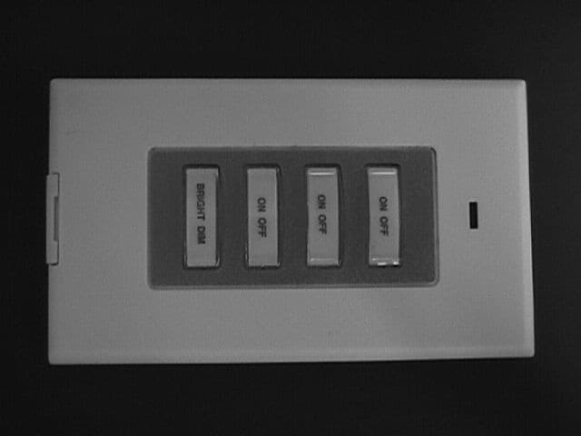
Click to zoom
Application Details
- Equipment Class
- DSC - Part 15 Security/Remote Control Transmitter
- Date of Grant
- Jun 23, 1999
- Application Purpose
- Original Equipment
- Date of Application
- May 18, 1999
- Equipment Note
- RF Wall Switch
- Frequency Range
- 310.00000000 - 310.00000000
- Company
- Authinx Inc.
- Country
- United States
Documents & Files
Document Text
Text extracted from the exhibit documents filed with the FCC. Open a document above to read the original.
Users Manual
X10 (USA) INC. LIMITED 1-YEAR WARRANTY X10 (USA) Inc. warrants X10 products to be free from defective material and workmanshipfor a period of one (1) year from the original date of purchase at retail. X10 (USA) Inc. agreesto repair or replace, at it’s sole discretion, a defective X10 product if returned to X10 (USA)Inc. within the warranty period and with proof of purchase.If service is required under this warranty:1. Return the defective unit postage prepaid to X10 (USA) Inc. (see address on back).2. Enclose a check for $4.00 to cover postage and handling.3. Enclose a dated proof of purchase.4. X10 is not responsible for shipping damage. Units to be returned should be packed carefully. 5. For additional warranty information, contact X10 (USA) Inc.Your Name ....................................................................................................................Address ....................................................................................................................... ... ............................................................................................................................... ......... Date Purchased .................. 19....... Store where purchased ............................................ Stick-A-Switch ™ (Model SS13A) Installation and operating instructions The SS13A works with the RR501 (part of the RC5000) and the TM751 (part of the RC6500). It letsyou turn on and off three individually coded X10 Modules and brighten and dim lights connected toLamp Modules and Wall Switch Modules. In the default state (after first fitting the battery) the SS13Ais set to Housecode A. The top three ON-OFF rocker keys control modules set to Unit Codes 1, 2, 3.The bottom rocker key brightens and dims lights connected to Lamp and Wall Switch Modules.1. Plug in an X10 Transceiver (RR501 or TM751, sold separately).2. To turn on or off X10 Modules set to Unit Codes 1, 2, or 3 (on Housecode A) press the left or right side of the first, second or third rocker key. To brighten or dim Lamp Modules or Wall SwitchModules press the number button first, then press and hold the left or right side of the bottomrocker key. Attach the SS13A to a wall using double sided tape or Velcro.™ If you want to controlModules 1, 2 and 3 on Housecode A, that's it. You don't need to read any further. To change the Housecode• Press and hold the first (top) ON rocker key. The red LED blinks once. 3 seconds later, the LED blinks the current setting: 1 blink for Housecode A, 2 blinks for B..... 16 blinks for P. • Release the first (top) ON rocker key. • Press and release the first (top) ON rocker key the appropriate number of times for the House Code you want to set. Once for A, twice for B, etc. The LED blinks for each press.IMPORTANT: Hold the button on your last press. 3 seconds later, the red LED blinks back thenew setting, e.g. 3 blinks for Housecode C. I f you do not follow this programming sequence, the LED will stay on for 1 second and your existing setting will not be changed. To change the Unit Code for the first (top) rocker key (the second and third rockers are always one # higher than the first). i.e. if you set the first rocker key to 6, the second rocker key controls7, and the third control 8, etc.. • Press and hold the top OFF rocker key . The red LED blinks once. 3 seconds later, the LED blinks the current setting: 1 blink for Unit Code 1, 2 blinks for 2, 16 blinks for 16. • Release the top OFF rocker key. • Press and release the top OFF rocker key the appropriate number of times for the Unit Code you want. IMPORTANT: Hold the key on your last press. 3 seconds later the new code blinksback. I f you do not follow this programming sequence, the LED will stay on for 1 second and your existing setting will not be changed. To change battery: open battery holder and fit a CR2032 Lithium 3V battery. Observe polarity. F.C.C. CAUTION - THIS DEVICE COMPLIES WITH PART 15 OF THE FCC RULES. OPERATION IS SUBJECT TO THE FOLLOWING TWO CONDITIONS: (1) THIS DEVICE MAY NOT CAUSEHARMFUL INTERFERENCE, AND (2) THIS DEVICE MUST ACCEPT ANY INTERFERENCERECEIVED, INCLUDING INTERFERENCE THAT MAY CAUSE UNDESIRED OPERATION.NOTE: NO CHANGES OR MODIFICATIONS MAY BE MADE TO THE UNITS. ANY CHANGES MADE TO THE UNITS WILL VOID THE USER'S AUTHORITY TO OPERATE THE EQUIPMENT. SS13A-5/99 Press left side to turn on, right sideto turn off modules set to UnitCodes 1, 2, and 3 on Housecode A(the default setting).Then press and hold left side tobrighten or right side to dim.Replace battery with CR2032, 3Vlithium type.
ID Label/Location Info
THIS DEVICE COMPLIES WITH PART 15 OF THE FCC RULES. OPERATION IS SUBJECT TO THE FOLLOWING TWO CONDITIONS: (1) THIS DEVICE MAY NOT CAUSE HARMFUL INTERFERENCE, AND (2) THIS DEVICE MUST ACCEPT ANY INTERFERENCE RECEIVED, INCLUDING INTERFERENCE THAT MAY CAUSE UNDESIRED OPERATION. NO SERVICEABLE PARTS INSIDE. Use CR2032, 3V lithium battery. For use with X-10 POWERHOUSE Wireless Transceivers. X-10 (USA) Inc., Closter, NJ 07624. www.x10.com Stick-A-Switch ™ Remote Wall Switch Model SS13A FCC ID: B4SSS13A Made in China SS13A rating label 2:1 5/17/99
Operational Description
Operational Description The SS13A is a 310 MHz transmitter used for remote control purposes. It is manually operated and ceases operation within 5 seconds after activation. It does not perform periodic transmissions.
Test Report
Data Sheet 1 of 2 Test Method: FCC Part 15 Subpart C Radiated Emissions Paragraph 15.231(b) Customer: X-10 (USA) Inc. Job No. R-8089-1 Test Sample: Pulsed RF Transmitter FCC ID: B4SSS13A Model No.: SS13A Serial No. N/A Operating Mode: Continuously Transmitter 309.7 Mhz Signal Technician: Dennis Cortes Date: May 18,1999 Notes: Test Distance: 3 Meters Temp: 23C Humidity:75C Detector: Peak Test Freq. Antenna Pol./Height EUT Orientation Meter Reading Correction Factor Corrected Reading Converted Reading Peak Limit Mhz(V/H) / DegreesX / Y / Z dBuv dB dBuV/m uV/m uV/m 309.7H-1.6X57.9-3.954.0501.258330 309.7H-1.0Y57.3-3.953.4467.758330 309.7H-1.0Z62.6-3.958.7861.058330 309.7V-1.5X63.1-3.959.2912.058330 309.7V-1.2Y63.5-3.959.6955.058330 309.7V-1.4Z46.7-3.942.8138.058330 619.4H-1.4X35.83.339.190.25833 619.4H-1.1Y34.03.337.373.35833 619.4H-1.4Z37.93.341.2114.85833 619.4V-1.7X41.23.344.5167.95833 619.4V-1.8Y41.53.344.8173.85833 619.4V-1.6Z34.23.337.575.05833 929.1H-1.0X47.27.754.9*555.95833 929.1H-1.0Y47.27.754.9*555.95833 929.1H-1.0Z47.27.754.9*555.95833 929.1V-1.0X47.27.754.9*555.95833 929.1V-1.0Y47.27.754.9*555.95833 929.1V-1.0Z47.27.754.9*555.95833 1238.8V + HX40.1-3.936.2*64.65833 1548.5V + HX41.6-0.341.3*116.15000 1858.2V + HX42.01.643.6*151.45833 2167.9V + HX41.5-1.340.2*102.35833 2477.6V + HX41.60.141.7*121.65833 2787.3V + HX40.61.442.0*125.95000 3097.0V + HX38.03.541.5*118.95833 The frequency range was scanned from 30 Mhz to 3.1 Ghz. All emissions not recorded were more Than 10 dB below the specified limit. Emissions from the EUT do not exceed the specified limits. *=Noise Floor Measurements ( Minimum system sensitivity) Data Sheet 2 of 2 Test Method: FCC Part 15 Subpart C Radiated Emissions Paragraph 15.231(b) Customer: X-10 (USA) Inc. Job No. R-8089-1 Test Sample: Pulsed RF Transmitter FCC ID: B4SSS13A Model No.: SS13A Serial No. N/A Operating Mode: Continuously Transmitter 309.7 Mhz Signal Technician: Dennis Cortes Date: May 18,1999 Notes: Test Distance: 3 Meters Duty Cycle: 28.5.0% Detector: Peak Duty Cycle Correction: -10.9 dB Test Freq. Antenna Pol./Height EUT Orientation Peak Reading Correction Factor Corrected Reading Converted Reading Average Limit Mhz(V/H) / DegreesX / Y / Z dBuv dB dBuV/m uV/m uV/m 309.7H-1.6X54.0-10.943.1142.95833 309.7H-1.0Y53.4-10.942.5133.45833 309.7H-1.0Z58.7-10.947.8245.55833 309.7V-1.5X59.2-10.948.3260.05833 309.7V-1.2Y59.6-10.948.7272.35833 309.7V-1.4Z42.8-10.931.939.45833 619.4H-1.4X39.1-10.928.225.7583 619.4H-1.1Y37.3-10.926.420.9583 619.4H-1.4Z41.2-10.930.332.7583 619.4V-1.7X44.5-10.933.647.9583 619.4V-1.8Y44.8-10.933.949.5583 619.4V-1.6Z37.5-10.926.621.4583 929.1H-1.0X54.9-10.944.0*158.5583 929.1H-1.0Y54.9-10.944.0*158.5583 929.1H-1.0Z54.9-10.944.0*158.5583 929.1V-1.0X54.9-10.944.0*158.5583 929.1V-1.0Y54.9-10.944.0*158.5583 929.1V-1.0Z54.9-10.944.0*158.5583 1238.8V + HX36.2-10.925.3*18.4583 1548.5V + HX41.3-10.930.4*33.1500 1858.2V + HX43.6-10.932.7*43.2583 2167.9V + HX40.2-10.929.3*29.2583 2477.6V + HX41.7-10.930.8*34.7583 2787.3V + HX42.0-10.931.1*35.9500 3097.0V + HX41.5-10.930.6*33.9583 The frequency range was scanned from 30 Mhz to 3.1 Ghz. All emissions not recorded were more Than 10 dB below the specified limit. Emissions from the EUT do not exceed the specified limits. *=Noise Floor Measurements ( Minimum system sensitivity) Data Sheet 3 of 2
Test Report
Test Report No. R-8089-1 FCC ID: B4SSS13A APPLICANT X-10 (USA), Inc. 91 Ruckman Road Closter, NJ 07624-0420 MANUFACTURER X-10 Electronics Shenzhen Co. Ltd. X-10 Building Labour Industrial District Shenzhen, Xixiang, Bao An Guang Dong, China, 518102 TEST SPECIFICATION: FCC Rules and Regulations Part 15, Subpart C, Para. 15.231 TEST PROCEDURE: ANSI C63.4:1992 TEST SAMPLE DESCRIPTION BRANDNAME: X-10 (USA), Inc. MODEL: SS13A TYPE: 310 MHz RF Transmitter POWER REQUIREMENTS: 3 VDC Via CR2032 Lithium Battery FREQUENCY OF OPERATION: 310 MHz TESTS PERFORMED Para. 15.231(a), Radiated Emissions, Fundamental and Harmonics Para. 15.231(c), Occupied Bandwidth Duty Cycle Determination REPORT OF MEASUREMENTS Applicant: X-10 (USA), Inc. Device:310 MHz RF Remote Control FCC ID: B4SSS13A Power Requirements: 3 VDC Via CR2032 Lithium Battery Applicable Rule Section:Part 15, Subpart C, Section 15.231 Test Report No. R-8089-1 FCC ID: B4SSS13A REPORT OF MEASUREMENTS (continued) TEST RESULTS 15.231 (a) -The device is used as a transmitter for security purposes. 15.231 (a)(1) & -The transmitter is manually operated and ceases transmission within 5 15.231(2)seconds after deactivation. 15.231 (a)(3) -The transmitter does not perform periodic transmissions. 15.231 (a)(4)-The device is employed for RC purposes involving security. 15.231 (b) -The fundamental field strength did not exceed 5833 μV/M (Average) at a test distance of 3 meters. In addition, the requirements of section 15.35 for averaging pulsed emissions and for limiting peak emissions were met. The field strength of harmonic and spurious emissions did not exceed 583 μV/M (AVERAGE). 15.231 (c) -The device operates at 310 MHz. The bandwidth of emissions did not exceed 0.25% of the operating frequency (775 kHz). DETERMINATION OF FIELD STRENGTH LIMITS The field strength limits shown below are found in Section 15.231. Frequency Limit F1=2603750 =L1 Fo=310Lo F2=47012500 =L2 The formula below was utilized to determine the limits: Limit = L1 + [(Fo-F1)(L2-L1)/(F2-F1)] Solving yields: Fundamental Limit= 5,833 μV/M (AVERAGE) @ 3 Meters Harmonic Limit= 583 μV/M (AVERAGE) @ 3 Meters Test Report No. R-8089-1 FCC ID: B4SSS13A REPORT OF MEASUREMENTS (continued) DETERMINATION OF DUTY CYCLE The unit’s RF output was directly coupled to the input of the spectrum analyzer. The analyzer was set for a frequency span of 0Hz. The sweep time was then adjusted in order to display one full pulse train. The transmitter on time was then summed and compared to the time for one full cycle in order to obtain the duty cycle.(See separate e-file attachments named Dutycycle pg1.pdf, Dutycycle pg 2.pdf, Dutycycle pg 3.pdf for plots) Transmitter On Time=28.5 milliseconds (maximum- worst case in 100 ms) Transmitter Cycle Time=108.4 milliseconds Transmitter Duty Cycle=28.5 % CALCULATION: 1 Large Pulse = 8.7 milliseconds 33 x 600 μs (small pulse)= 19.8 milliseconds 8.7 + 19.8= 28.5 milliseconds Duty Cycle=28.5 % Correction Factor = 20 log(0.285) = -10.9 SPECTRUM ANALYZER DESENSITIZATION CONSIDERATIONS Due to the nature of the emissions being measured, care was taken to ensure that the resolution bandwidth of the spectrum analyzer was adequate to provide accurate measurements. The following formula was utilized: Setting pulse desensitization equal to zero and utilizing the minimum observed pulse width of 600μs yields a minimum required bandwidth of 1111 Hz. FCC specified bandwidths of 100kHz and 1MHz were utilized below and above 1GHz, respectively. Test Report No. R-8089-1 FCC ID: B4SSS13A REPORT OF MEASUREMENTS (continued) GENERAL NOTES 1. All readings were taken utilizing a peak detector function at a test distance of 3 meters. 2. The duty cycle was applied to the peak readings in order to determine the average value of the emissions. 3. All measurements were made with 3 VDC Via CR2032 Lithium Battery. 4. The frequency range was scanned from 30 MHz to 3.1 GHz . All emissions not reported were more than 20 dB below the specified limit. Test Report No. R-8089-1 FCC ID: B4SSS13A EQUIPMENT LIST FCC Part 15 Subpart C Radiated Emissions Paragraph 15.231(b) ENTypeManufacturerFrequency Range Model No.Cal Date Due Date 067Open Area Test SiteRetlif3 MeterRNY8/30/978/30/99 128CDouble Ridge GuideEaton Corporation1 GHz - 18 GHz9600110/6/9810/6/99 133Broadband Pre-AmplifierElectro-Metrics10 kHz - 1 GHz, 26dBBPA-10006/22/986/22/99 141Spectrum AnalyzerHewlett Packard100 Hz - 40 GHz8566B3/16/999/16/99 141AGraphics PlotterHewlett PackardN/A7470A3/5/993/5/00 141BQuasi-Peak AdaptorHewlett Packard100 Hz - 1 GHz85650A3/16/999/16/99 206B6.0 dB AttenuatorTexscan0 - 1.0 GHzFP-50 - 6 dB6/22/986/22/99 523BiconilogElectro-Mechanics26 - 2000 MHz3142B10/22/984/22/00 543PreamplifierHewlett Packard1.0 GHz - 26.5 GHz8449B9/3/989/3/99 Test Report No. R-8089-1 FCC ID: B4SSS13A FCC 15.231(b) RADIATED EMISSIONS, FUNDAMENTAL & SPURIOUS CASE (See separate e-file attachment named 310Mhz231.Doc) Test Report No. R-8089-1 FCC ID: B4SSS13A FCC 15.231(c) OCCUPIED BANDWIDTH (See separate e-file attachment named OccBw1.pdf and OccBw2.pdf) Test Report No. R-8089-1 FCC ID: B4SSS13A DUTY CYCLE PLOTS (See separate e-file attachment named Dutycycle pg1.pdf, Dutycycle pg 2.pdf, and Dutycycle pg 3.pdf)
Contact Information
Applicant
Shane Houshmand(Chief Operating Officer)
Technical Contact
Retlif Testing LaboratoriesThomas J Schneider
[email protected]516-737-1500
795 Marconi Avenue · Ronkonkoma, New York · United States
Non-Technical Contact
Retlif Testing LaboratoriesMichelle Tirado
[email protected]516-737-1500
Technical Specifications
| # | Rule Parts | Frequency Range | Power Output |
|---|---|---|---|
| 1 | 15C | 310 MHz - 310 MHz | - |
Other Applications from Authinx Inc.

B4SXC35A
Jun 16, 2011Wireless Color Camera
Equipment Class
DXX - Part 15 Low Power Communication Device Transmitter
B4SVT50
Jun 16, 2011Wireless Audio/Video System
Equipment Class
DXX - Part 15 Low Power Communication Device Transmitter
B4SVR50
Jun 13, 2011Wireless Audio/Video Receiver
Equipment Class
DSC - Part 15 Security/Remote Control Transmitter
B4S-XC30A
Jun 07, 2011Wireless Color Camera
Equipment Class
DXX - Part 15 Low Power Communication Device Transmitter
B4SIR34A
Aug 01, 2010Remote Control Transmitter
Equipment Class
DSC - Part 15 Security/Remote Control Transmitter