B4SUX24AIR SENSOR/ WIRELESS TRANSMITTER
Authinx Inc.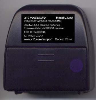
Click to zoom
Application Details
- Equipment Class
- DSC - Part 15 Security/Remote Control Transmitter
- Date of Grant
- Dec 12, 2006
- Application Purpose
- Original Equipment
- Date of Application
- Dec 12, 2006
- Equipment Note
- IR SENSOR/ WIRELESS TRANSMITTER
- Frequency Range
- 433.92000000 - 433.92000000
- Company
- Authinx Inc.
- Country
- United States
Documents & Files
Document Text
Text extracted from the exhibit documents filed with the FCC. Open a document above to read the original.
Users Manual
X10 Wireless Technology, Inc. LIMITED 1-YEAR WARRANTY X10.com, a division of X10 Wireless Technology, Inc. (X10) warrants X10 products to befree from defective material and workmanship for a period of one (1) year from the originaldate of purchase at retail. X10 agrees to repair or replace, at it’s sole discretion, a defectiveX10 product if returned to X10 within the warranty period and with proof of purchase.If service is required under this warranty:1. Call 1-800-675-3044 or visit www.x10.com, or e-mail [email protected] to obtain a Return Merchandise Authorization (RMA) number. 2. Return the defective unit postage prepaid to X10 (see address on back).3. Enclose a check for $4.00 to cover postage and handling.4. Enclose a dated proof of purchase.5. X10 is not responsible for shipping damage. Units to be returned should be packed carefully. Please visit www.x10.com/warrantyto complete your on-line warranty registration. Thank you.For help or more information on setup, please visit: www.x10.com/support Installation and operating instructions for UX24A Transmitterand UX25A Receiver, both included in the UX2400 Set.1. Insert two AAA alkaline batteries in the UX24A transmitter, and place it in the room where you want to use your remote control (up to 20 feet away fromwhere you normally sit). Make sure the front of the unit is facing you. 2. Plug the UX25A receiver’s power supply jack into the back of the UX25A and plug the power supply into an AC wall outlet in the room where your TV, VCR,stereo, etc., that you want to control is located 3. Plug the IR extender cable into the back of the UX25A.4. Attach the IR emitters on the cable to the front of up to two A/V devices that you want to control. UX2400-11/06 THIS DEVICE COMPLIES WITH PART 15 OF THE FCC RULES. OPERATION IS SUBJECT TOTHE FOLLOWING TWO CONDITIONS: (1) THIS DEVICE MAY NOT CAUSE HARMFULINTERFERENCE, AND (2) THIS DEVICE MUST ACCEPT ANY INTERFERENCE RECEIVED,INCLUDING INTERFERENCE THAT MAY CAUSE UNDESIRED OPERATION.This equipment generates and uses radio frequency energy, and if not installed and used properly, thatis, in strict accordance with the manufacturers instructions, it may cause interference to radio andtelevision reception. It has been type tested and found to comply with the limits for remote controldevices in accordance with the specifications in Sub-Parts B and C of Part 15 of FCC Rules, whichare designed to provide reasonable protection against such interference in a residential installation.However, there is no guarantee that interference will not occur in a particular installation. If thisequipment does cause interference to radio or television reception, which can be determined byunplugging the equipment, try to correct the interference by one or more of the following measures.• Reorient the antenna of the radio/TV experiencing the interference.• Relocate the equipment with respect to the radio/TV.• Move the equipment away from the radio/TV.• Plug the equipment into an outlet on a different electrical circuit from the radio/TV experiencing the interference. • If necessary, consult your local Dealer for additional suggestions.NOTE: Modifications to this product will void the user's authority to operate this equipment. 5. Point your remote control at the UX24A Powermid Transmitter and press any button. The Powermid Transmitter receives the Infrared (IR) signals from yourremote and converts them to Radio Frequency (RF) codes. It sends thesecodes (even through walls and ceilings) to the UX25A Powermid Receiverwhich converts the codes back to IR codes to control your TV, VCR, etc. Note: The Transmitter and Receiver can be in different rooms, up to 100 feet awayfrom each other. You can add more Transmitters to use your remotes in more thanone room. Add more Receivers to control A/V equipment in more than one room. Cable Box DVD Player IR emitter IR emitter IR extender jack UX25A Receiver
Block Diagram
1 2 34 ABCD 4 3 2 1 D CBA Title Number Revision Size A4 Date: 13-Nov-2006 Sheet of File: A:\PWRTX-BD.SCH Drawn By: IR Sensor Amplifier 433.92MHz TRANSMITTER 433.92MHz BLOCK DIAGRAM FOR POWERMID TRANSMITTER IR
ID Label/Location Info
Powermid rating label artwork 2:1 11/30/06 UX24A X10 POWERMID ™ IR Sensor/Wireless Transmitter www.x10.com/support Use two AAA alkaline batteries For use with Model UX25A receiver. Model UX24A FCC ID: B4SUX24A IC: 1632A-UX24A Made in China
Operational Description
UX24A Operational Description-433 MHz transmitter: The UX24A radio frequency pulsed transmitter that operates at 433 MHz. The transmitter is used to extend Infrared Transmitter range. The Pulse Coded transmitter commands are received by the UX25A receiver and convert the codes back to Infrared codes to control at TV, VRC, etc.
Parts List/Tune Up Info
ptnoDesQtyRef UX24APowermid Transmitter (433.92MHz)0.000 038010=10040-XLABEL-DATE CODE (WHITE)1.000 038010=10513-2433 MC LABEL1.000 038020=12954RATING LABEL ST10A1.000 183010=13240RUBBER FOOT (D=5.00)2.000 183010=14801BATTERY DOOR,SILVER1.000 185000=25843FRONT CAB,IR BLUE,ELECTIA1.000 185000=25851BACK CABINET,SILVER1.000 403011=10406SPRING CONTACT,COM1.000 851001=12543PCB ASSY1.000 038010=10513-2433 MC LABEL1.000 042010=11594APCB1.000 076=10000023CAP-MCC 10P 5% NPO 06034.000C5,7,18,22 076=10100023CAP-MCC 100P 5% NPO 06031.000C6 076=10400014CAP-MCC 100N 10% X7R 06036.000 C3,19,21,23,24,42 076=10500016CAP-MCC 1U +8-2 Y5V 08052.000C4,8 076=10900012CAP-MCC 1P .25P NPO 06031.000C25 076=12100023CAP-MCC 120P 5% NPO 06031.000C10 076=18000023CAP-MCC 18P 5% NPO 06031.000C41 076=20900012CAP-MCC 2P .25P NPO 06031.000C40 076=22000023CAP-MCC 22P 5% NPO 06031.000C12 076=22200014CAP-MCC 2N2 10% X7R 06031.000C1 076=25900012CAP-MCC 2P5 .25P NPO 06031.000C11 076=30900012CAP-MCC 3P .25P NPO 06033.000C28,29,38 076=33000023CAP-MCC 33P 5% NPO 06031.000C39 076=47200014CAP-MCC 4N7 10% X7R 06031.000C30 076=50800012CAP-MCC 0P5 .25P NPO 06031.000C37 076=56000023CAP-MCC 56P 5% NPO 06032.000C13,20 076=70900012CAP-MCC 7P .25P NPO 06032.000C27,31 076=80900012CAP-MCC 8P .25P NPO 06031.000C32 080=00000010SAW RESONATOR 433.92MHZ1.000Y1 162089=10050COIL 10T5R ID=1,WD=0.222.000L1,2 209=00000003TRS-NPN 2SC3356 SMD R251.000Q8 209=00000017TRS-NPN 9014D (SOT-23)5.000Q1-5 210117=10070TRS-NPN MPS H10 SMD1.000Q7 210=00000000TRS-PNP 2N3906 SMD1.000Q6 211328=10124IC 4069 SMD1.000U2 212107=10015DIODE-SI 1N4148, SMD1.000D1 212107=10016DIODE-DUAL BAV99 (SOT-23)1.000D2 220=00200180LED 3MM (RED DIFFUSED)1.000LED1 224200=10000DIODE-P INFRARED PH302/2B1.000D5 241=10000003RES-TFC 10R 5% 1/10W 06031.000R23 241=10300003RES-TFC 10K 5% 1/10W 06033.000R6,14,17 241=10400003RES-TFC 100K 5% 1/10W06031.000R3 241=10500003RES-TFC 1M 5% 1/10W 06032.000R4,15 241=15100003RES-TFC 150R 5% 1/10W06031.000R18 241=15300003RES-TFC 15K 5% 1/10W 06031.000R13 241=18400003RES-TFC 180K 5% 1/10W06031.000R10 241=22500003RES-TFC 2M2 5% 1/10W 06031.000R8 241=33500003RES-TFC 3M3 5% 1/10W 06031.000R9 241=47000003RES-TFC 47R 5% 1/10W 06032.000R20,21 241=47300003RES-TFC 47K 5% 1/10W 06034.000R1,2,7,12 241=47400003RES-TFC 470K 5%1/10W 06031.000R11 241=47500003RES-TFC 4M7 5% 1/10W 06031.000R5 241=68100003RES-TFC 680R 5% 1/10W06031.000R24 241=68200003RES-TFC 6K8 5% 1/10W 06032.000R16,19 354=12600009WIRE UL1007 #26 WHITE0.065ANT 403011=10404SPRING CONTACT (+VE)1.000 403011=10405SPRING CONTACT (-VE)1.000 403041=10112METAL BOX1.000
Schematics
1 2 3 4 5 6 78 ABCD 8 7 6 5 4 3 2 1 D CBA Title Number Revision Size A3 Date: 10-Nov-2006 Sheet of File: A:\PWRMID-2.SCH Drawn By: ANTENNA 433.92MHz Battery Powermid Tx R16 6K8 R17 10K R18 150R R19 6K8 R20 47R R21 47R C25 1P C11 2P5 C23 100N C12 22P C13 56P C19 100NC28 3P C27 7P C18 10P C31 7P Y1 433.92MHz Q7 H10 Q8 2SC3356 L1 47N L2 47N +3V C37 0P5 +3V PCB1 PCB2 C29 3P +3V C20 56P C10120P C26 * U2C 4069 U2B4069 U2A4069 Q6 3906 R15 1M C24 100N U2E4069 U2F4069 R13 15K C5 10P C7 10P C6 100P R14 10K C22 10P C32 8P R22 * D1 1N4148 D2 BAV99 D5 PH302/2B C36 * R3 100KQ1 9014 Q2 9014 Q3 9014 R5 4M7 R4 1M R1 47K R7 47K R2 47K C3 100N R8 2M2 R6 10K +3V R10 180K R9 3M3 Q4 9014 Q5 9014 C30 4N7 R11 470K R12 47K C1 2N2 C2 * C4 1U C21 100N IR DATA IR DATA 13 12 C8 1U 98 123456 PCB : 042010=11594A R23 10R NOTE : ALL UNSPECIFIED RESISTOR & CAPACITOR ARE USE 0603 SMD TYPE 04 PCB ASSY : 851001H12543 14 7 +3V +3V LED1 3MM RED R24 680R C40 2P C41 18P C42 100N BATT1 1.5V AAA SIZE BATT2 1.5V AAA SIZE C43 * +3V LEDO LEDO C39 33P C38 3P
Test Report
Retlif Testing Laboratories, Test Report R-11714-1, X10 (USA), Inc., FCC ID: B4SUX24A Page 1 of 21 Technical Information Applicant Manufacturer Name: X10 (USA), Inc. Name: X-10 Electronics (Shenzhen) Co. Ltd. Address: 19823 58 th Place South Address: Together Rich Industrial Park B Sanwei Industrial District, Xixiang Town City, State, Zip: Kent, WA 98032 City, State, Zip: Baoan County, Shenzhen, China Test Specification: FCC Rules and Regulations Part 15, Subpart C, Para. 15.231 Test Procedure: ANSI C63.4:2003 Test Sample Description Test Sample: IR Sensor / Wireless Transmitter Brandname: X10 (USA), Inc. Model Number: UX24A FCC ID: B4SUX24A Type: Pulsed Transmitter Power Requirements: 2 AAA (1.5V) Alkaline batteries Frequency of Operation: 433.92 MHz Applicable Rule Section: Part 15, Subpart C, Section 15.231 Tests Performed Para. 15.231(a), Radiated Emissions, Fundamental and Harmonics Para. 15.231(b), Radiated Emissions, Spurious Case Para. 15.231(b), Duty Cycle Determination Para. 15.231(c), Occupied Bandwidth Retlif Testing Laboratories, Test Report R-11714-1, X10 (USA), Inc., FCC ID: B4SUX24A Page 2 of 21 Test Results 15.231 (a): This device transmits a control signal and is used as an: remote control transmitter. 15.231 (a)(1) The transmitter is manually operated. Transmission ends within 5 seconds of deactivation. 15.231 (a)(3): The transmitter does not perform periodic transmissions. 15.231 (b): The fundamental field strength did not exceed 10996.6 μV/M (Average) at a test distance of 3 meters. In addition, the requirements of section 15.35 for averaging pulsed emissions and for limiting peak emissions were met. The field strength of harmonic and spurious emissions did not exceed 1099.6 μV/M (AVERAGE). 15.231 (c) The Bandwidth of the emission was no wider than 0.25% of the center frequency (82.4 kHz) as measured 20 db down from the modulated carrier. Retlif Testing Laboratories, Test Report R-11714-1, X10 (USA), Inc., FCC ID: B4SUX24A Page 3 of 21 Determination of Field Strength Limits The field strength limits shown below are found in Section 15.231: Frequency Limit F1 = 260 3750 = L1 Fo = 433.92 MHz Lo F2 = 470 12500 = L2 The formula below was utilized to determine the limits: Limit = L1 + [(Fo-F1)(L2-L1)/(F2-F1)] Solving Yields Fundamental Limit = 10996.6 μV/M (AVERAGE) @ 3 Meters Harmonic Limit = 1099.6 μV/M (AVERAGE) @ 3 Meters Duty Cycle Determination The unit’s RF output was directly coupled to the input of the spectrum analyzer. The analyzer was set for a frequency span of 0 Hz. The sweep time was then adjusted in order to display one full pulse train. The transmitter on time was then summed and compared to the time for one full cycle in order to obtain the duty cycle. (See plots for additional information.) Transmitter On Time =27.0 milliseconds (maximum per cycle) Transmitter Cycle Time = 103.0 milliseconds (100 ms maximum) Transmitter Duty Cycle =27.0 % Calculation 1 Small Pulse =0.48 milliseconds 34.0 x 0.78 μs (Large pulse) = 26.52 milliseconds 0.48 + 26.52=27.0 milliseconds Duty Cycle (26.98/100)*100 =27.0 % Correction Factor =20 log (0.27)= -11.3 dB Retlif Testing Laboratories, Test Report R-11714-1, X10 (USA), Inc., FCC ID: B4SUX24A Page 4 of 21 Spectrum Analyzer Desensitization Considerations Due to the nature of the emissions being measured, care was taken to ensure that the resolution bandwidth of the spectrum analyzer was adequate to provide accurate measurements. The following formula was utilized: minimum bandwidth = 1/{minimum pulse width (in seconds) x 1.5} = Hz Setting pulse desensitization equal to zero and utilizing the minimum observed pulse width of 480.0 μs yields a minimum required bandwidth of 1389 Hz. FCC specified bandwidths of 100 kHz and 1 MHz were utilized below and above 1 GHz, respectively. General Notes 1. All readings were taken utilizing a peak detector function at a test distance of 3 meters. 2. The duty cycle was applied to the peak readings in order to determine the average value of the emissions. 3. The frequency range was scanned from 30 MHz to 4.34 GHz. All emissions not reported were more than 20 dB below the specified limit. Retlif Testing Laboratories, Test Report R-11714-1, X10 (USA), Inc., FCC ID: B4SUX24A Page 5 of 21 Certification and Signatures We certify that this report is a true representation of the results obtained from the tests of the equipment stated. We further certify that the measurements shown in this report were made in accordance with the procedures indicated and vouch for the qualifications of all Retlif Testing Laboratories personnel taking them. Donald C. Lerner EMC Test Engineer Richard J. Reitz Laboratory Manager Non-Warranty Provision The testing services have been performed, findings obtained and reports prepared in accordance with generally accepted laboratory principles and practices. This warranty is in lieu of all others, either expressed or implied. Non-Endorsement This test report contains only findings and results arrived at after employing the specific test procedures and standards listed herein. It is not intended to constitute a recommendation, endorsement or certification of the product or material tested. This test report must not be used by the client to claim product endorsement by NVLAP or any agency of the U.S. Government. Retlif Testing Laboratories, Test Report R-11714-1, X10 (USA), Inc., FCC ID: B4SUX24A Page 6 of 21 EQUIPMENT LIST Radiated Emissions EN Type Manufacturer Description Model No. Cal Date Due Date 067 Open Area Test Site Retlif 3 Meter RNY 9/12/2006 9/12/2009 091 Shielded Enclosure Retlif 10 kHz - 1 GHz Room 6 10/16/2006 10/16/2007 128 Double Ridged Guide Electro-Mechanics 1 GHz - 18 GHz 3105 3/27/2006 3/27/2007 133 Broadband Pre-Amplifier Electro-Metrics 10 kHz - 1 GHz, 26dB BPA-1000 6/27/2006 6/27/2007 141 Spectrum Analyzer Hewlett Packard 100 Hz - 40 GHz 8566B 10/10/2006 4/10/2007 141B Quasi-Peak Adaptor Hewlett Packard 100 Hz - 1 GHz 85650A 10/9/2006 4/9/2007 141C Cab…
Text truncated - open the document above for the full version.
Test Setup Photos
Retlif Testing Laboratories, Test Report R-11714-1, X10 (USA), Inc., FCC ID: B4SUX24A Page 1 of 3 Radiated Emissions, Fundamental and Harmonics, X-Axis Radiated Emissions, Fundamental and Harmonics, Y-Axis Retlif Testing Laboratories, Test Report R-11714-1, X10 (USA), Inc., FCC ID: B4SUX24A Page 2 of 3 Radiated Emissions, Fundamental and Harmonics, Y-Axis Occupied Bandwidth Retlif Testing Laboratories, Test Report R-11714-1, X10 (USA), Inc., FCC ID: B4SUX24A Page 3 of 3 Radiated Emissions, Spurious Test Setup Duty Cycle
Contact Information
Applicant
Shane Houshmand(Chief Operating Officer)
Test Firm
Retlif Testing LaboratoriesScott Wentworth
Technical Specifications
| # | Rule Parts | Frequency Range | Power Output |
|---|---|---|---|
| 1 | 15.231 | 433.92 MHz - 433.92 MHz | - |
Other Applications from Authinx Inc.

B4SXC35A
Jun 16, 2011Wireless Color Camera
Equipment Class
DXX - Part 15 Low Power Communication Device Transmitter
B4SVT50
Jun 16, 2011Wireless Audio/Video System
Equipment Class
DXX - Part 15 Low Power Communication Device Transmitter
B4SVR50
Jun 13, 2011Wireless Audio/Video Receiver
Equipment Class
DSC - Part 15 Security/Remote Control Transmitter
B4S-XC30A
Jun 07, 2011Wireless Color Camera
Equipment Class
DXX - Part 15 Low Power Communication Device Transmitter
B4SIR34A
Aug 01, 2010Remote Control Transmitter
Equipment Class
DSC - Part 15 Security/Remote Control Transmitter